
Use Pcf8574(a) I2c Gpio To Add More Digital Pins To Arduino

About the project
Easily add more digital inputs and outputs to your Arduino.
Project info
Difficulty: Easy
Estimated time: 1 hour
License: GNU General Public License, version 3 or later (GPL3+)
Items used in this project
Hardware components

Software apps and online services
Story
No matter how many ports an Arduino board has, they never seem to be enough for the cool new project you have in mind. Luckily there is a solution. The Arduino has both I2C and SPI pins, and there are a number of I2C and SPI GPIO chips, and modules built with those chips. One of the cheapest and most widely used one is the PCF8574/PCF8574A. On the positive side it is widely available and there are ready cheap modules with it. The down side is that it has only 8 channels. The good news is that you can connect multiple such modules on the same I2C channel.
In this tutorial, I will show you how you can use the PCF8574/PCF8574A GPIO I2C Module to add 8 more digital channels to your Arduino Nano.
Components
1 / 2 • Picture 1

Picture 1

Picture 2
Set the PCF8574/PCF8574A I2C Address
1 / 3 • Picture 1

Picture 1

Picture 2

Picture 3
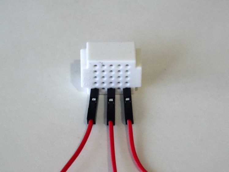
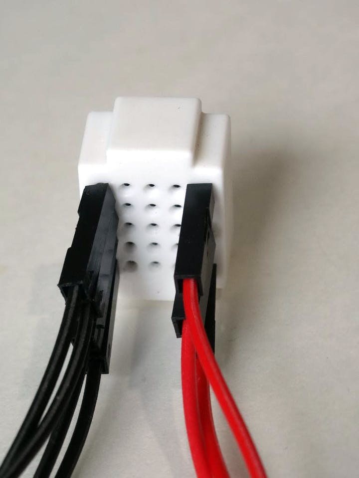
My PCF8574/PCF8574A GPIO Module has Jumpers that can be used to specify the I2C address.
If you position each Jumper to the "-" side it will set to value Zero (Picture 1) for the Address bit, and if you switch it to the "+" side, it will set One (Picture 3) for the Address bit.
The PCF8574 and PCF8574A have a different set of addresses. The following is the table of addresses based on the +/- settings of the jumpers:
- A2="-", A1="-", A0="-" for PCF8574 (32), for PCF8574A (56) (Picture 1)
- A2="-", A1="-", A0="" for PCF8574 (33), for PCF8574A (57) (Picture 2)
- A2="-", A1="", A0="-" for PCF8574 (34), for PCF8574A (58)
- A2="-", A1="", A0="" for PCF8574 (35), for PCF8574A (59)
- A2="", A1="-", A0="-" for PCF8574 (36), for PCF8574A (60)
- A2="", A1="-", A0="" for PCF8574 (37), for PCF8574A (61)
- A2="", A1="", A0="-" for PCF8574 (38), for PCF8574A (62)
- A2="", A1="", A0="" for PCF8574 (39), for PCF8574A (63) (Picture 3)
1 / 3 • Picture 1

Picture 1

Picture 2

Picture 3
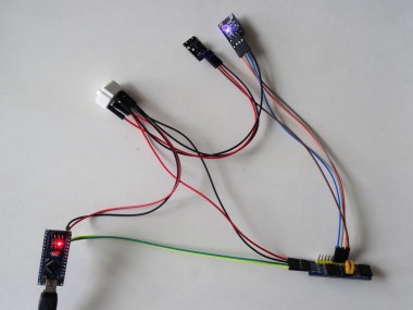
- Connect Power (Red wire), and Ground (Black wire) to the PCF8574/PCF8574A GPIO Module (Picture 1), and leave the Male ends unconnected
- Connect SDA (Green wire), and SCL (Yellow wire) to the PCF8574/PCF8574A GPIO Module (Picture 1)
- Connect the other end of the SDA (Green wire) to SDA/Analog pin 4 of the Arduino Nano board (Picture 2)
- Connect the other end of the SCL (Yellow wire) to SCL/Analog pin 5 of the Arduino Nano board (Picture 2)
- Connect Ground (Black wire) to the Ground pin of the Arduino board (Picture 2), and leave the Male end unconnected
- Connect another Power (Red wire) to the 5V Power pin of the Arduino board (Picture 2), and leave the Male end unconnected
- Picture 3 shows where the Ground, 5V Power, SDA/Analog pin 4, and SCL/Analog pin 5 pins are for the Arduino Nano
1 / 3 • Picture 1

Picture 1

Picture 2

Picture 3
- Connect Button Signal (Brown wire) to the "Signal" Pin of the Button Module
- Connect Power (Red wire) to the "+" pin of the Button Module
- Connect Ground (Black wire) to the "-" pin of the Button Module
- Connect Ground (Black wire) to the "-" pin of the LED Module
- Connect LED (Blue wire) to the "B" pin of the LED Module
- Connect LED (Gray wire) to the "G" pin of the LED Module
- Connect LED (Orange wire) to the "R" pin of the LED Module
- Connect the Button Signal (Brown wire) to the P0 pin of the PCF8574/PCF8574A
- Connect the LED (Orange wire) to the P1 pin of the PCF8574/PCF8574A
- Connect the LED (Gray wire) to the P2 pin of the PCF8574/PCF8574A
- Connect the LED (Blue wire) to the P3 pin of the PCF8574/PCF8574A
Connect the Male ends of the 3 Power wires (Red wires) - from the Button Module, the PCF8574/PCF8574A, and the Arduino together as example with the help of a Breadboard (Picture 1) - In my case I used a small Breadboard.
Step 6: Connect the Ground Wires together
Connect the Male ends of the 4 Ground wires (Black wires) - from the LED Module, the Button Module, the PCF8574/PCF8574A, and the Arduino together as example with the help of a Breadboard (Picture 1) - In my case I used a small Breadboard.
Start Visuino, and select the Arduino Board type
1 / 2 • Picture 1

Picture 1

Picture 2
To start programming the Arduino, you will need to have the Arduino IDE installed. Please be aware that there are some critical bugs in Arduino IDE 1.6.6. Make sure that you install 1.6.7 or higher, otherwise this tutorial will not work!
- Start Visuino as shown in the first picture
- Click on the "Tools" button on the Arduino component (Picture 1) in Visuino
- When the dialog appears, select "Arduino Nano" as shown in Picture 2
1 / 3 • Picture 1

Picture 1

Picture 2

Picture 3
First we need to add component to control the PCF8574/PCF8574A GPIO:
- From the Component Toolbox expand the "Input/Output" Category, then the "Digital" sub-category, select the "PCF8574/PCF8574A GPIO" component (Picture 1), and drop it in the design area (Picture 2)
- In the Object Inspector, you may need to change the value of the "Address" property of the GPIO component (Picture 2)
- Connect the "Out" pin of the GPIO1 component to the "In" pin of the "I2C" channel of the Arduino component (Picture 3)
1 / 6 • Picture 1

Picture 1

Picture 2

Picture 3

Picture 4

Picture 5

Picture 6
Next we will add components to have button clocking a counter and sending the first 3 bits of the counter to the Red, Green, and Blue color pins of the LED:
- Type "button" in the Filter box of the Component Toolbox then select the "Debounce Button" component (Picture 1), and drop it in the design area.
- Type "count" in the Filter box of the Component Toolbox then select the "Counter" component (Picture 2), and drop it in the design area
- Type "to un" in the Filter box of the Component Toolbox then select the "Integer To Unsigned" component (Picture 3), and drop it in the design area
- Type "to dig" in the Filter box of the Component Toolbox then select the "Unsigned To Digital" component (Picture 4), and drop it in the design area (Picture 5)
- In the Object Inspector set the value of the "Output Pins" property of the UnsignedToDigital1 component to "3" (Picture 6)
1 / 5 • Picture 1

Picture 1

Picture 2

Picture 3

Picture 4

Picture 5
- Connect the "Out" output pin of the "Channel[ 0 ]" channel of the GPIO1 component to the "In" input pin of the Button1 component (Picture 1)
- Connect the "Out" output pin of the Button1 component to the "In" input pin of the Counter1 component (Picture 2)
- Connect the "Out" output pin of the Counter1 component to the "In" input pin of the IntegerToUnsigned1 component (Picture 3)
- Connect the "Out" output pin of the IntegerToUnsigned1 component to the "In" input pin of the UnsignedToDigital1 component (Picture 4)
- Click in the "Out" box containing the pins of the UnsignedToDigital1 component to start connecting all the Out pins at once (Picture 5)
- Move the mouse over the "In" input pin of the "Channel[ 1 ]" channel of the GPIO1 component. The Visuino will automatically spread the wires so they will connect correctly to the rest of the pins (Picture 5)
1 / 2 • Picture 1

Picture 1

Picture 2
- In Visuino, Press F9 or click on the button shown on Picture 1 to generate the Arduino code, and open the Arduino IDE
- In the Arduino IDE, click on the Upload button, to compile and upload the code (Picture 2)
1 / 2 • Picture 1

Picture 1

Picture 2
Congratulations! You have completed the project.
Picture 1 and the Video show the connected and powered up project. Every time you press the Button the counter will increment, and the LED will change its color.
On Picture 2 you can see the complete Visuino diagram. Also attached is the Visuino project, that I created. You can download and open it in Visuino: https://www.visuino.com
Credits
Related products


Leave your feedback...