
Ultrasonic Ranger(ping) Distance Lcd 16x2 I2c Display

About the project
Learn how easy it is to connect Ultrasonic Sensor to Arduino and display the distance on a LCD Display with Visuino.
Project info
Difficulty: Easy
Estimated time: 1 hour
License: GNU General Public License, version 3 or later (GPL3+)
Items used in this project

Software apps and online services
Story
In this tutorial, I will show you how easy it is to connect Ultrasonic Sensor to Arduino and display the distance on a LCD Display.
Step 1: Components
1 / 2 • Picture 1

Picture 1

Picture 2
- One Arduino compatible board (I use Arduino Nano, because I have one, but any other will be just fine)
- One Ultrasonic Ranger Sensor Module - I used HC-SR04, but US-015, or very much any other will also work
- One I2C 16x2 LCD Display (Back side of the LCD with the I2C adapter showed on Picture 2)
- One small Breadboard (Any breadboard can be used, or any other way to connect 3 wires together)
- 3 Female-Male (Red) jumper wires
- 6 Female-Female jumper wires
1 / 3 • Picture 1

Picture 1

Picture 2

Picture 3
- Connect Female-Female Ground (black wire), SDA (green wire), and SCL (yellow wire) to the LCD Module (Picture 1)
- Connect the Female end of a Female-Male Power (red wire) to the VCC/Power pin of the LCD Module (Picture 1) , and leave the Male end unconnected
- Connect the other end of the Ground wire (black) to Ground pin of the Arduino board (Picture 2)
- Connect the other end of the SDA wire (green) to SDA/Analog pin 4 of the Arduino Nano board (Picture 2)
- Connect the other end of the SCL wire (yellow) to SCL/Analog pin 5 of the Arduino Nano board (Picture 2)
- Connect another Female-Male Power wire (red) to the 5V Power pin of the Arduino board (Picture 2), and leave the Male end unconnected
- Picture 3 shows where are the Ground, 5V Power, SDA/Analog pin 4, and SCL/Analog pin 5 pins of the Arduino Nano
1 / 4 • Picture 1

Picture 1

Picture 2

Picture 3

Picture 4
- Connect Ground (black), Power (red), Trigger (brown), and Echo (purple) to the Ultrasonic Ranger Sensor Module (Picture 1)
- Connect the Male ends of the 3 Power wires (red) - from the Display, the Ultrasonic Ranger Module, and the Arduino together as example with the help of a Breadboard (Picture 2) - In my case I used a small Breadboard
- Connect the other end of the Ground wire (black) to Ground pin of the Arduino board (Picture 3)
- Connect the other end of the Trigger wire (brown) to Digital pin 2 of the Arduino board (Picture 3)
- Connect the other end of the Echo wire (purple) to Digital pin 3 of the Arduino board (Picture 3)
- Picture 4 shows in Red where are the Ground, Digital 2, and Digital 3 pins of the Arduino Nano (In Blue are shown the connections made in the previous step)
1 / 2 • Picture 1

Picture 1

Picture 2
To start programming the Arduino, you will need to have the Arduino IDE installed from here: http://www.arduino.cc/ .
Please be aware that there are some critical bugs in Arduino IDE 1.6.6.
Make sure that you install 1.6.7 or higher, otherwise this Tutorial will not work!
The Visuino: https://www.visuino.com also needs to be installed.
- Start Visuino as shown in Picture 1
- Click on the "Tools" button on the Arduino component (Picture 1) in Visuino
- When the dialog appears, select Arduino Nano as shown in Picture 2
1 / 4 • Picture 1

Picture 1

Picture 2

Picture 3

Picture 4
- Type "sonic" in the Filter box of the Component Toolbox then select the "Ultrasonic Ranger(Ping)" component (Picture 1), and drop it in the design area
- In the Object Inspector set the value of the "PauseTime" property of the UltrasonicRanger1 to 1000 (Picture 2) This will give 1 second period between the measurements, so the LCD display will not be updated too often
- Connect the "Ping(Trigger)" pin of the UltrasonicRanger1 component to the "Digital" input pin of the Digital[ 2 ] channel of the Arduino component (Picture 3)
- Connect the "Out" pin of the Digital[ 3 ] channel of the Arduino component to the "Echo" input pin of the UltrasonicRanger1 component (Picture 4)
1 / 4 • Picture 1

Picture 1

Picture 2

Picture 3

Picture 4
- Type "lcd" in the Filter box of the Component Toolbox then select the "Liquid Crystal Display (LCD) - I2C" component (Picture 1), and drop it in the design area
- Click on the "Tools" button (Picture 2) to open the "Elements" editor (Picture 3)
We will add a Text field with the description of the value:
- Add Text field for the Distance description text by select the "Text Field" in the right window of the "Elements" editor, and clicking on the "" button on the left (Picture 3)
- In the Object Inspector set the "Initial Value" property of the element to "Distance:" (Picture 4) - This will specify the text to be displayed
1 / 2 • Picture 1

Picture 1

Picture 2
- Add Analog field for the Distance value by selecting the "Analog Field" in the right window of the "Elements" editor, and clicking on the "" button on the left (Picture 1)
- In the Object Inspector set the "Precision" property of the element to "2" (Picture 2)
- In the Object Inspector set the "Row" property of the element to "1" (Picture 2) - This will specify that the field will be shown in the second row of the Display
- In the Object Inspector set the "Width" property of the element to "6" (Picture 2)
1 / 4 • Picture 1

Picture 1

Picture 2

Picture 3

Picture 4
- Add Text field for the Units text selecting the "Text Field" in the right window of the "Elements" editor, and clicking on the "" button (Picture 1)
- In the Object Inspector set the "Column" property of the element to "7" (Picture 2)
- In the Object Inspector set the "Initial Value" property of the element to "CM" (Picture 3)
- In the Object Inspector set the "Row" property of the element to "1" (Picture 3)
- Close the Elements editor
1 / 3 • Picture 1

Picture 1

Picture 2

Picture 3
- Connect the "Out" pin of the UltrasonicRanger1 component (Picture 1) to the "In" pin of the "Elements.AnalogField1" element of the LiquidCrystalDisplay1 component (Picture 2)
- Connect the "Out" pin of the LiquidCrystalDisplay1 component to the to the "In" pin of the I2C channel of the Arduino component (Picture 3)
1 / 2 • Picture 1

Picture 1

Picture 2
- In Visuino, Press F9 or click on the button shown on Picture 1 to generate the Arduino code, and open the Arduino IDE
- In the Arduino IDE, click on the Upload button, to compile and upload the code (Picture 2)
1 / 2 • Picture 1

Picture 1

Picture 2
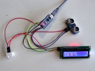
Congratulations! You have completed the project.
Picture 1 shows the connected and powered up project. As you can see on the picture the Display will show the Distance to the nearest object from the Ultrasonic Ranger.
On Picture 2 you can see the complete Visuino diagram.Also attached is the Visuino project, that I created for this Tutorial. You can download and open it in Visuino: https://www.visuino.com
Credits
Related products


Leave your feedback...