
Ultimate Dry Ice Machine - Bluetooth, 3d Printed, Aa Battery

Made by DIY-Machines / 3D Printing / Fire & Pyrotechnics / Holidays / Robotics
About the project
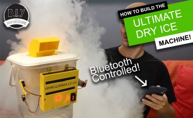
A portable, 3D printable, AA battery powered, bluetooth controlled Dry Ice machine with integrated LED effects. What's not to love? Great for Halloween, Parties, First wedding dances, photography and theatrical effects. :)
Items used in this project
Hardware components


View all
Story
Step 1: Video Instructions
If you prefer to follow an instructional video then I have created one which you can watch. It's also great if you want to see what this machine is like - I show both types of nozzles that I designed at the beginning of the video.
The written instructions and photos follow now...
Step 2: You Will Need...
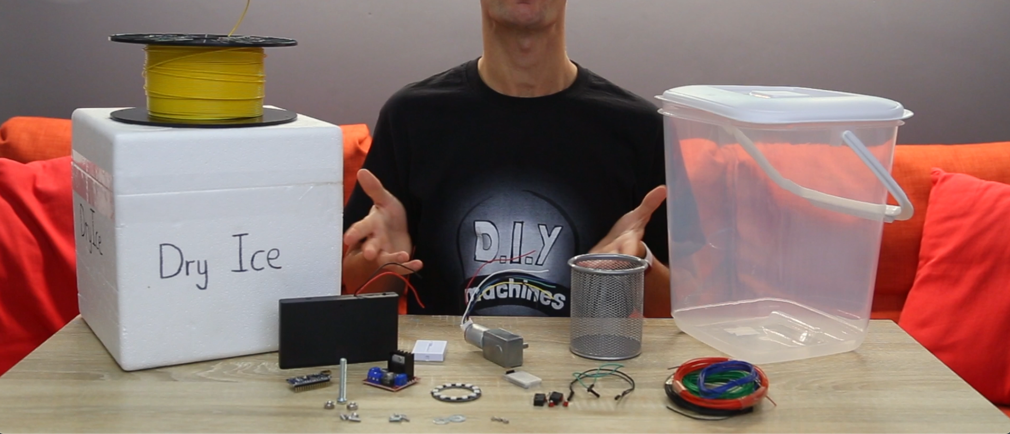
You will of course need some supplies to make one of your own. Here is a list of those items as well as links to where you can find them on Amazon:
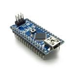
■ Elegoo Arduino Nano (x1): https://geni.us/ArduinoNanoV3
■ L298N Motor Driver (x1): https://geni.us/L298N
■ 8 AA Battery Holder (x1): https://geni.us/8aaBatteryHolder
■ AA Batteries (x8): https://geni.us/AABatteries
■ Mini breadboard (x1): https://geni.us/MiniBreadboard
■ 12v Geared DC Motor (x1): https://geni.us/12VGearedDCMotor
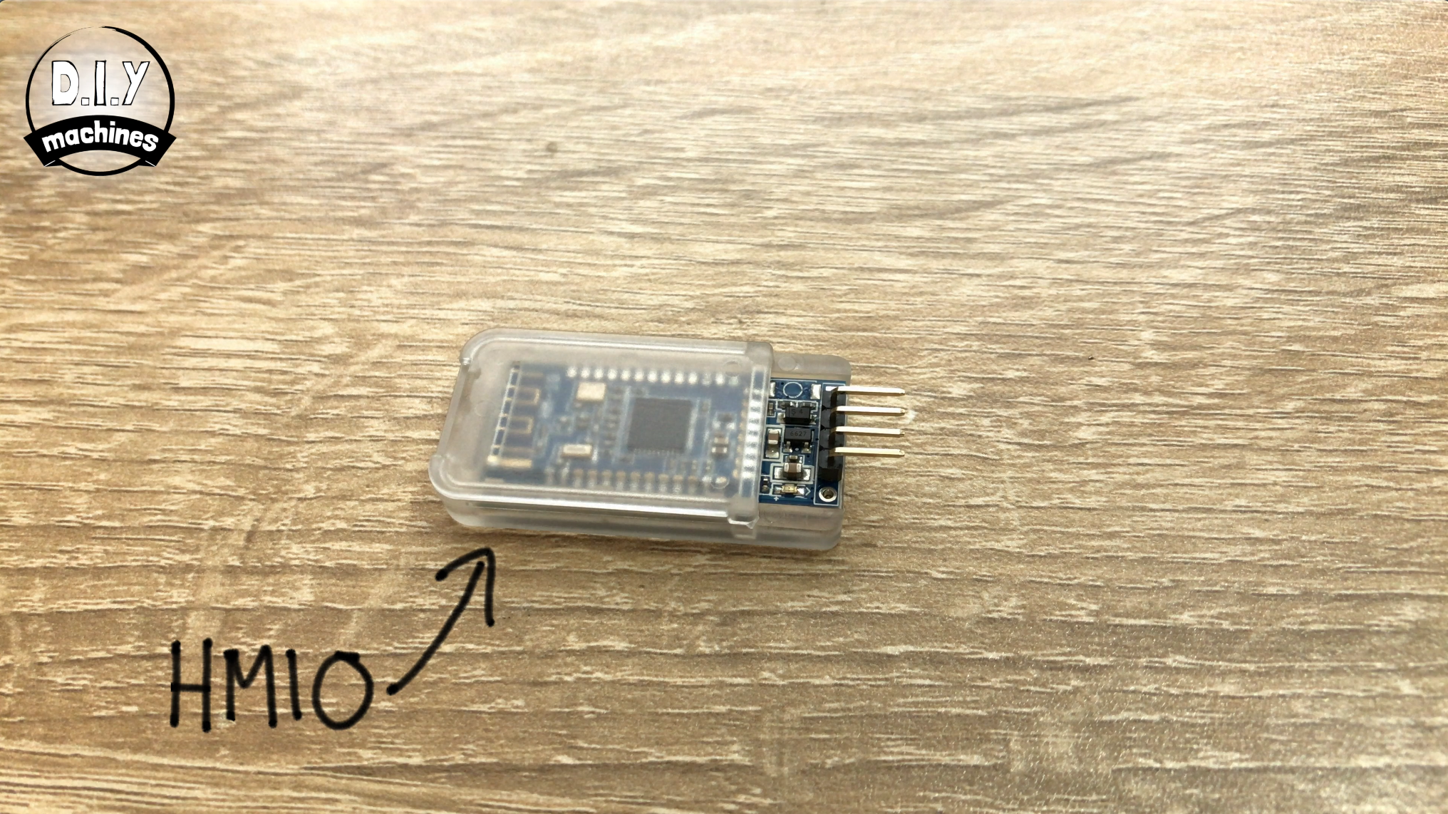
■ HM10 Bluetooth Module (x1): https://geni.us/HM10Bluetooth
■ Contact Switches (x2): https://geni.us/ContactSwitch
■ Stationery Holder (x1): https://geni.us/StationeryHolder
■ Nuts and Bolts - : http://geni.us/NutsAndBolts
■ Wire: https://geni.us/22AWGWire
■ PLA Filament: https://geni.us/PLAFilament
■ Plastic Container (x1): https://geni.us/PlasticContainer The one I used measured about 20cm across, 20cm wide and 27cm high.
These are some of my favourite tools I use and can recommend:
■ Battery powered glue gun: http://geni.us/BoschBatteryGlueGun
■ Bosch Bit Driver: https://geni.us/Bosch-Screwdriver
You will also need a 3D printer for the 3D printed parts. However, you may be handy with either wood or metalwork and be able to fabricate your own parts instead of 3D printing them.
You will also need some dry ice once you have finished building your project. A quick word of warning:
Dry ice is extremely cold and will burn you if it touches your bare skin. Follow all of the safety instruction provided by your dry ice supplier and you will have plenty of fun without having to take anyone to A&E.
Step 3: Printing the 3D Files
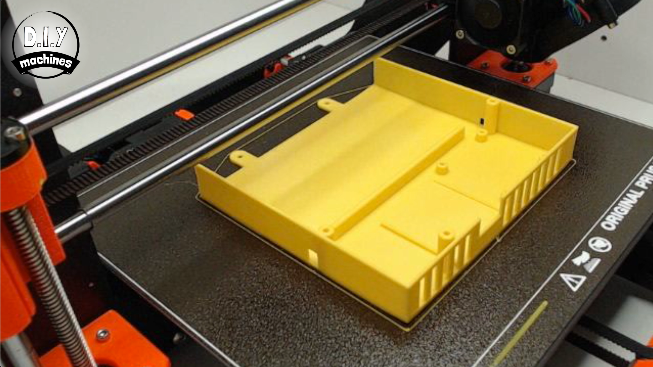
You will need to print several parts for this project. They can be found over on my Thingiverse page: https://www.thingiverse.com/thing:3902329/files
The prints are:
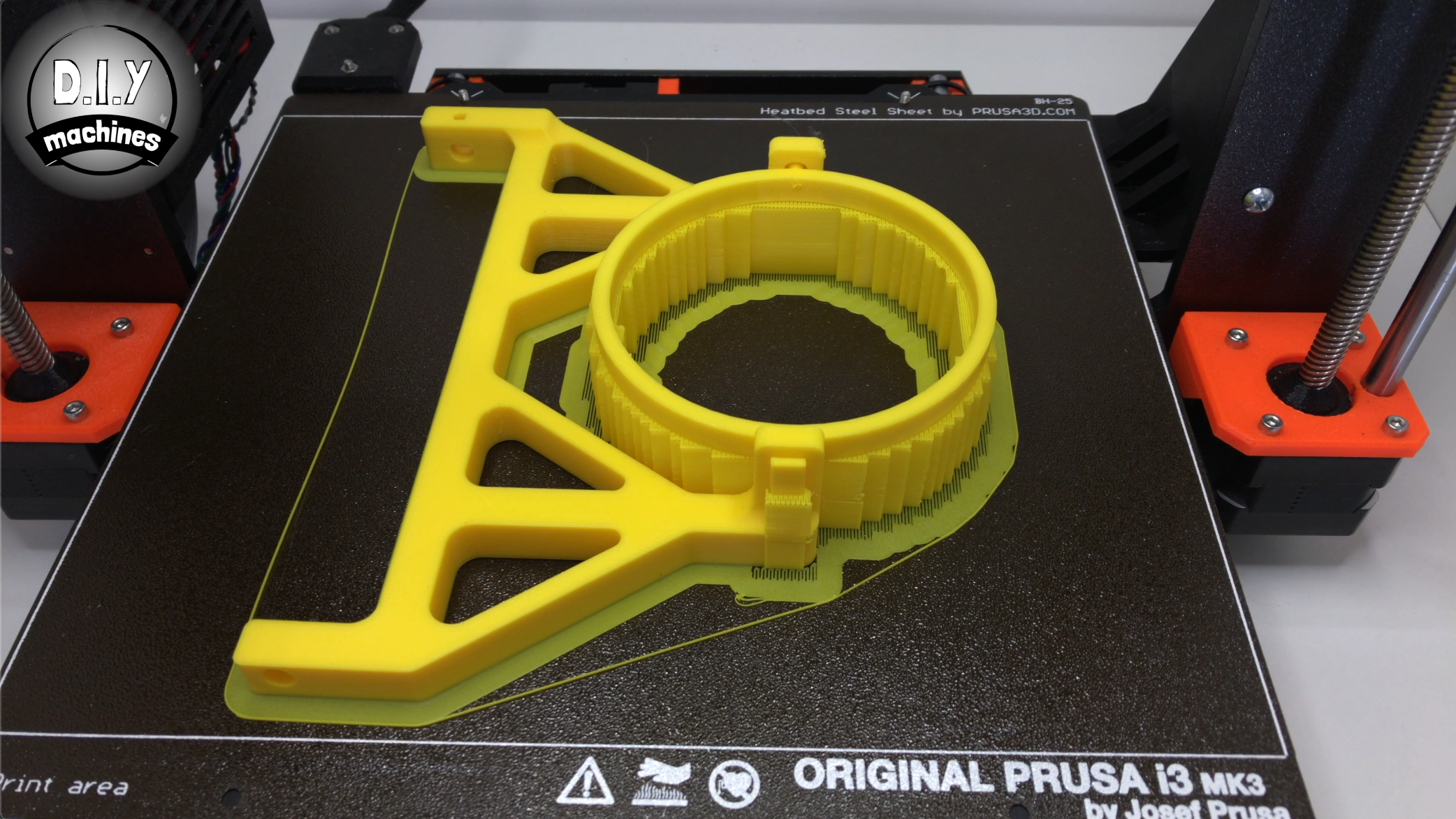
- Dry_Ice_Arms.STL I printed this in PLA with a 60% infill so as to be able to withstand both the cold and hot temperatures for longer. I used a layer height of 0.2mm and supports as this print includes print-in-place gimbal like part.
- Electronics_Holer_-_Top.STL Printed in PLA. Layer height not so important with this part, or infill percentage.
- Electronics_Holer_-_Bottom.STL Printed in PLA. Layer height or infill percentage again does not matter so much with this part.
- Limit_Arm.STL Same as the above.
We will talk about printing the nozzles later on in this guide when we get to the part about assembling them.
Once you have printed the Dry Ice Arms you will need to take a couple of minutes to carefully remove the support material.
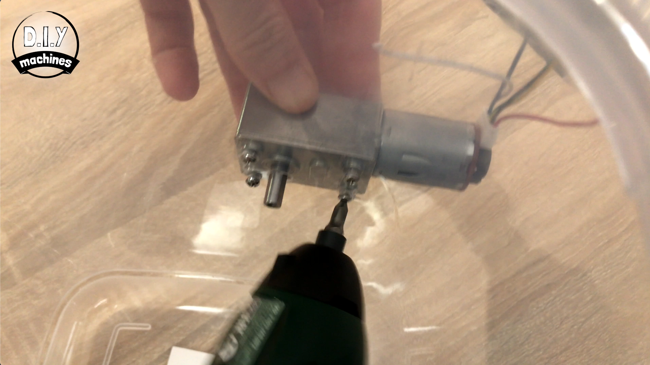
Step 4: Installing the Motor
For this step prepare:
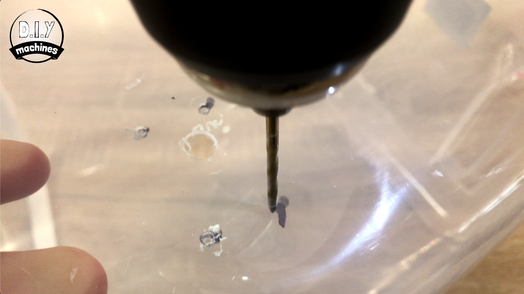
- Drill and 8mm drill bit
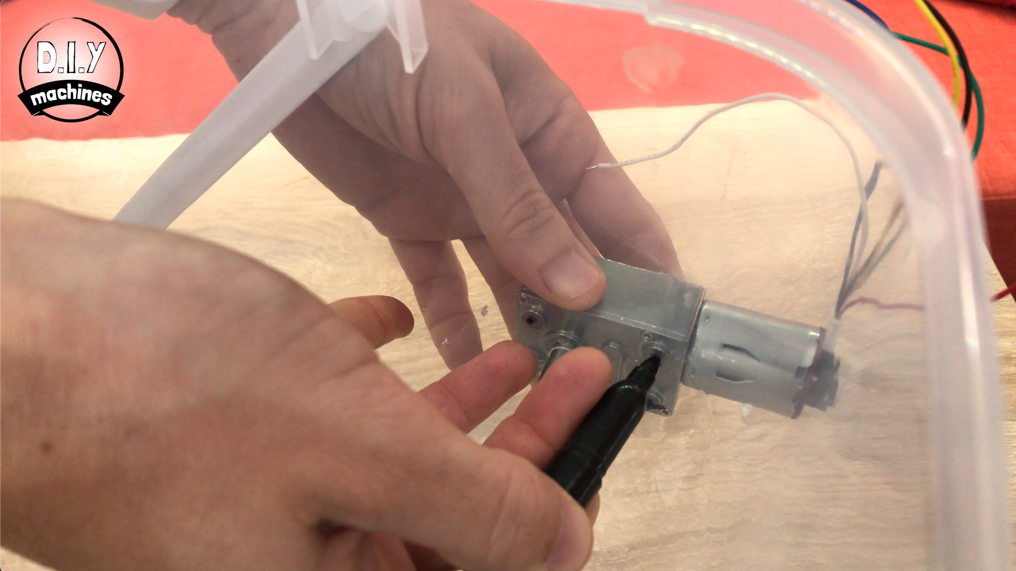
- Marker pen
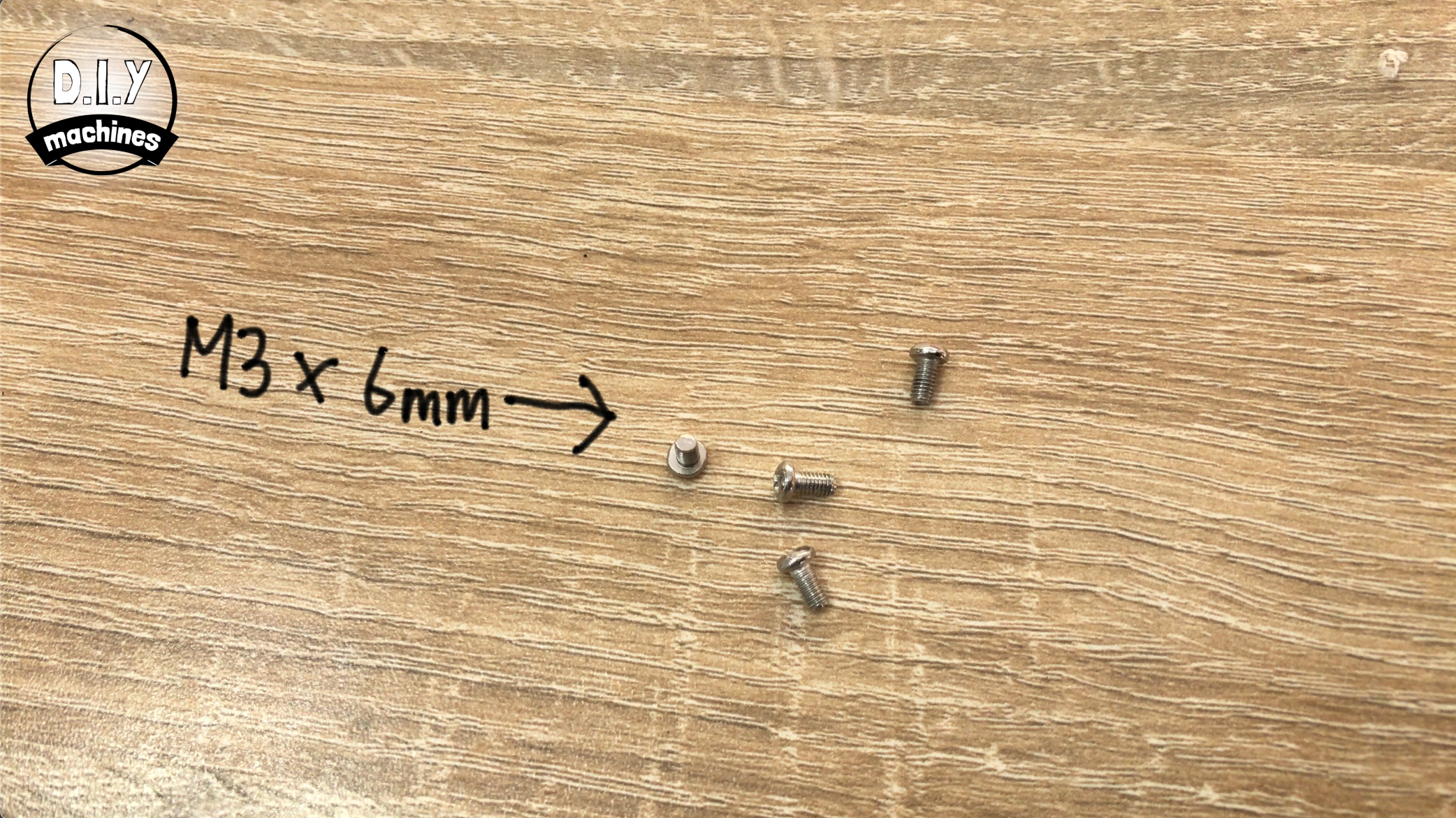
- M3 x 6 bolts (x4)
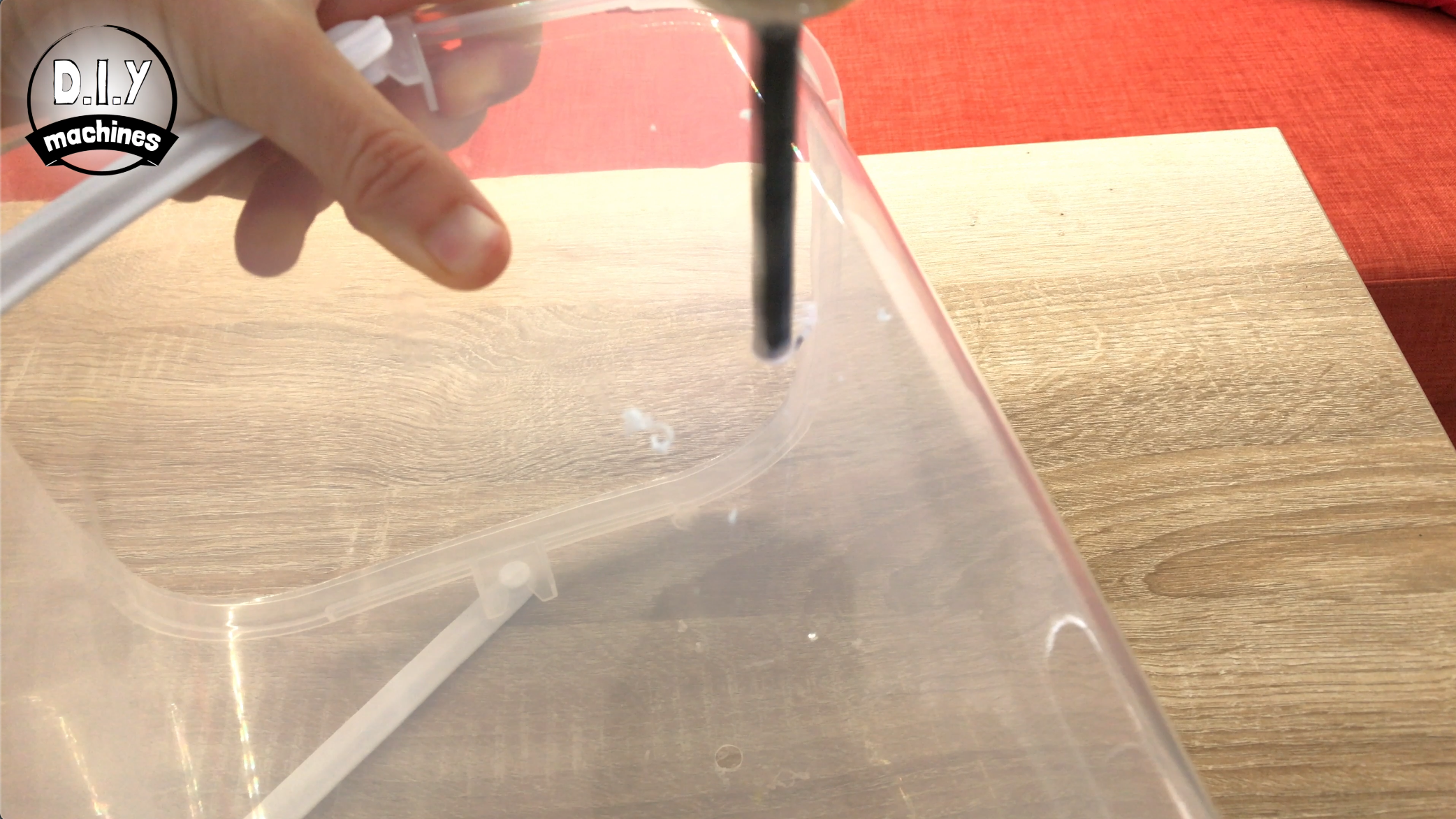
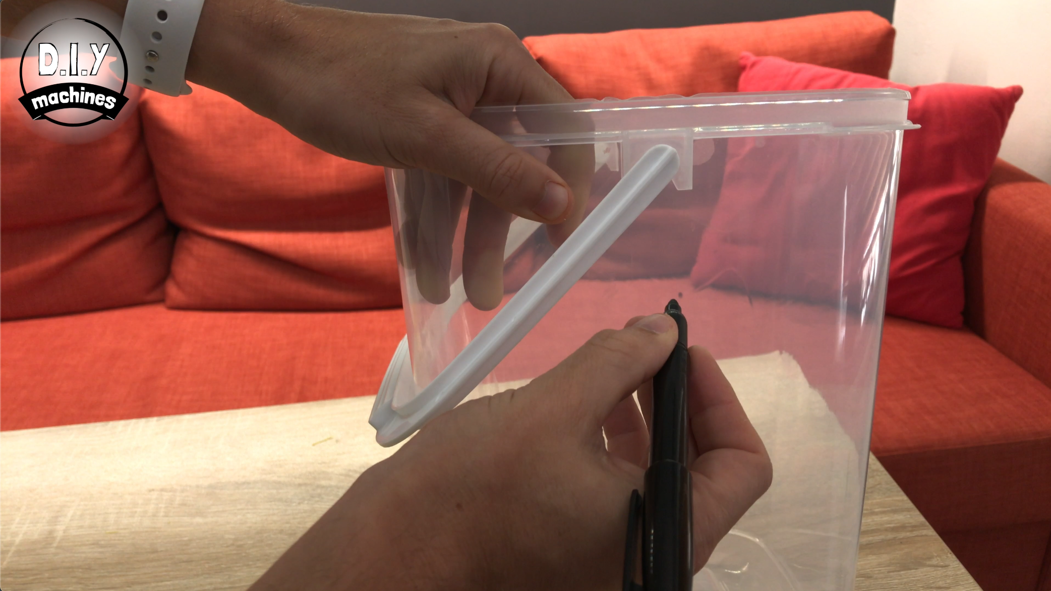
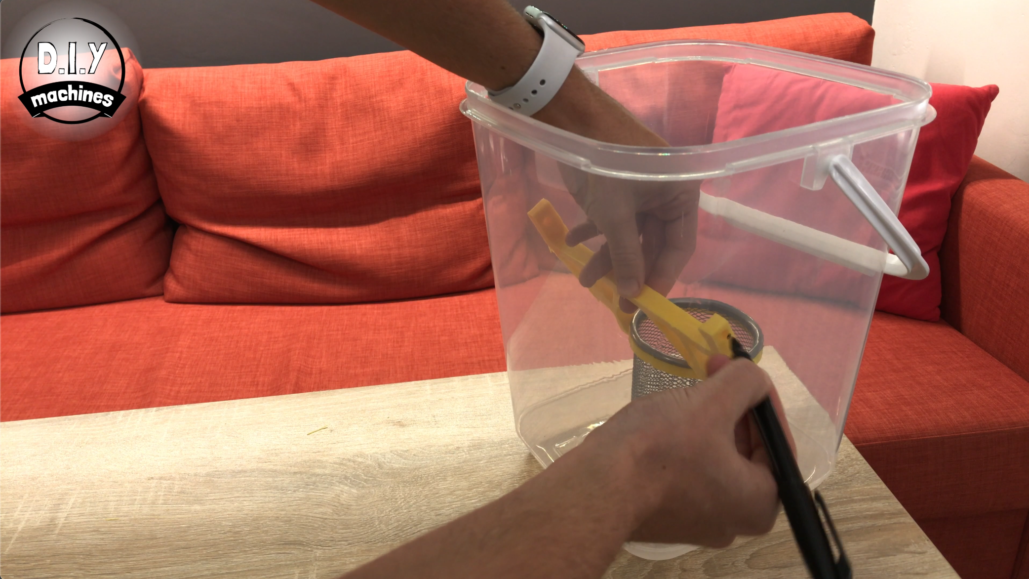
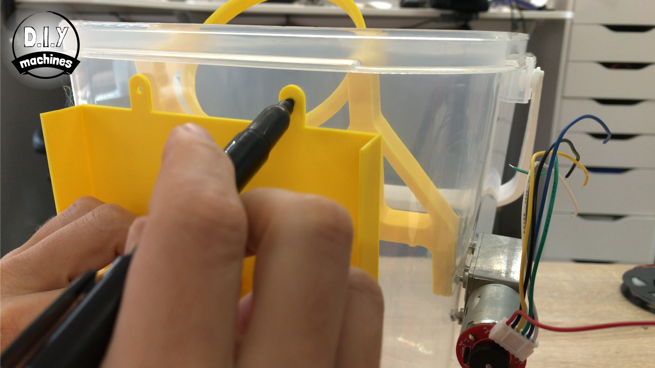
Put the stationery/pen pot into the arms which we just printed. Lower this inside your container and then mark on the side where we need to drill a hole so that the arm is able to move up and down without colliding with the rest of the container. Make another mark on the opposite side of the container.
Drill both of these marks out with an 8mm drill bit.
Offer up the motor to one side of the container and then draw where we need the screw holes to be able to mount the motor. Drill these four marks out again, but this time, use a 3mm drill bit.
Use four of the M3 x 6 bolts to secure the motor into place.
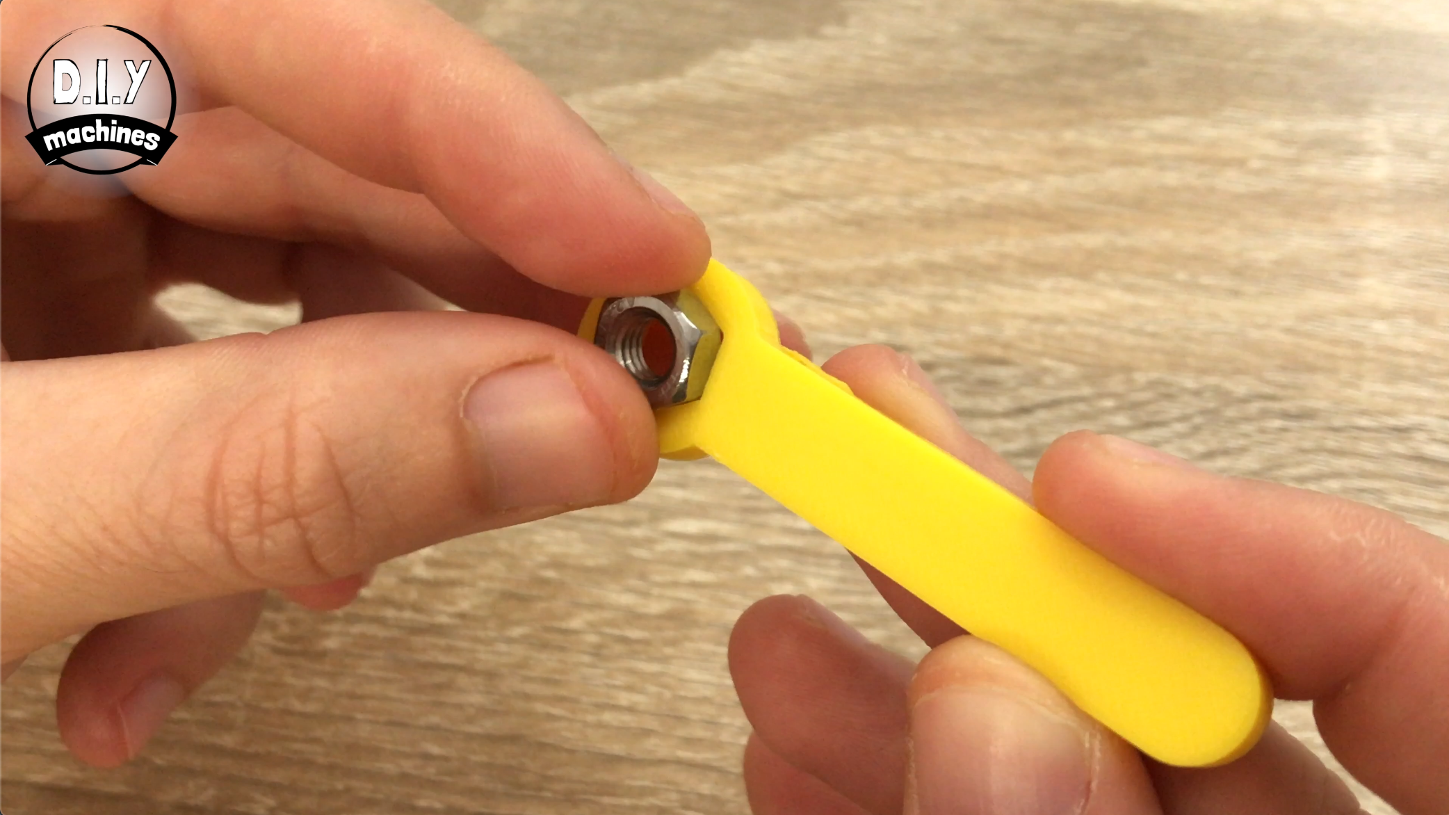
Step 5: Fitting the Bucket Arm
For this step prepare:
- M3 Nut
- M3 x 6 bolt
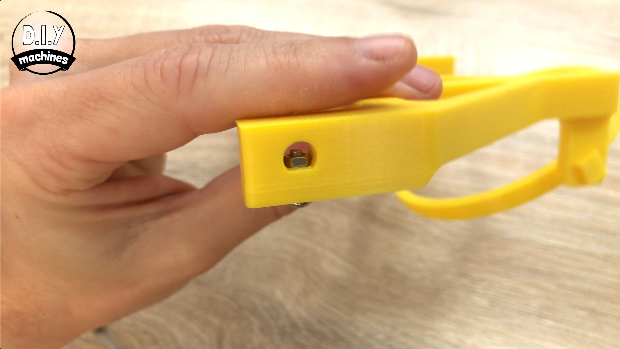
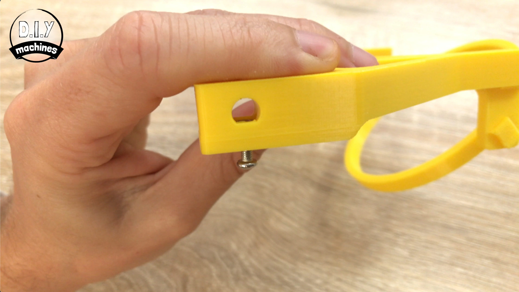
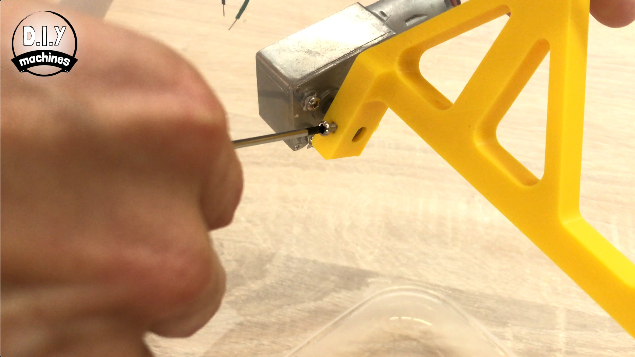
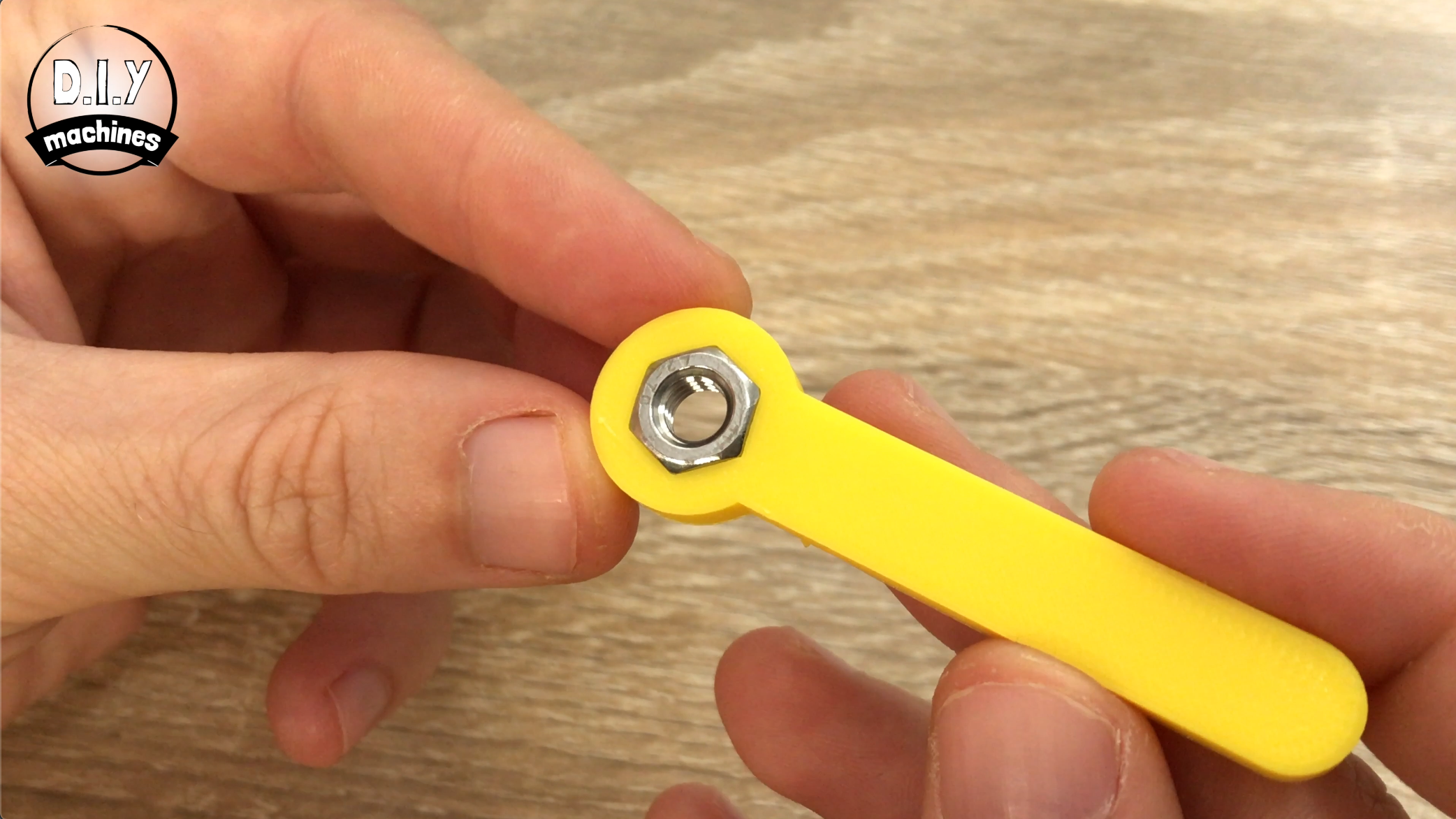
Using a small allen key or similar, insert a M3 nut into the holder just inside the shaped opening at one end of the arm. Then insert an M3 x 6 bolt through the hole parallel to this. Screw the bolt until it has pulled the nut firmly into its recess, then undo the bolt again - not all the way, just enough that we can no longer see any of its threaded length inside through the shaped hole.
Once this is done you can slide it over the shaft of the motor. Ensure that you match the flat section of the motor shaft with where our nut and bolt are. Tighten the bolt slightly against this flat area on the shaft being mindful not to over tighten so as to damage our 3D print.
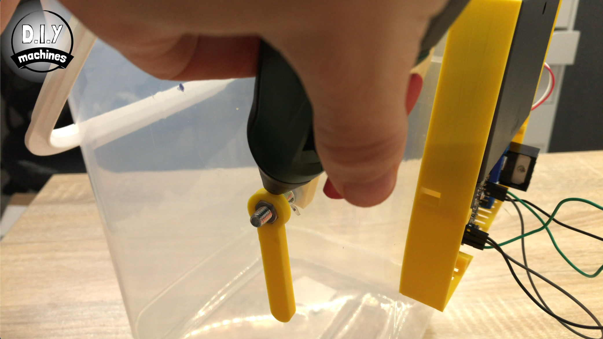
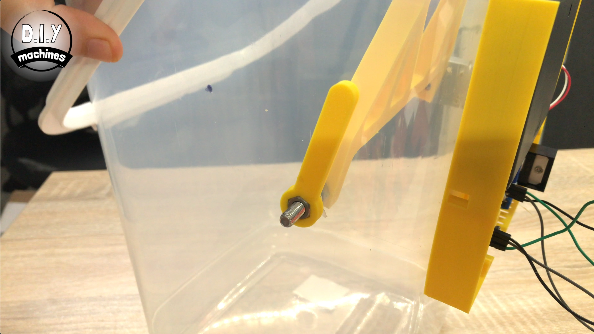
Step 6: Connect the Other End of the 'arm' and Assemble 'limit Lever'
For this step prepare:
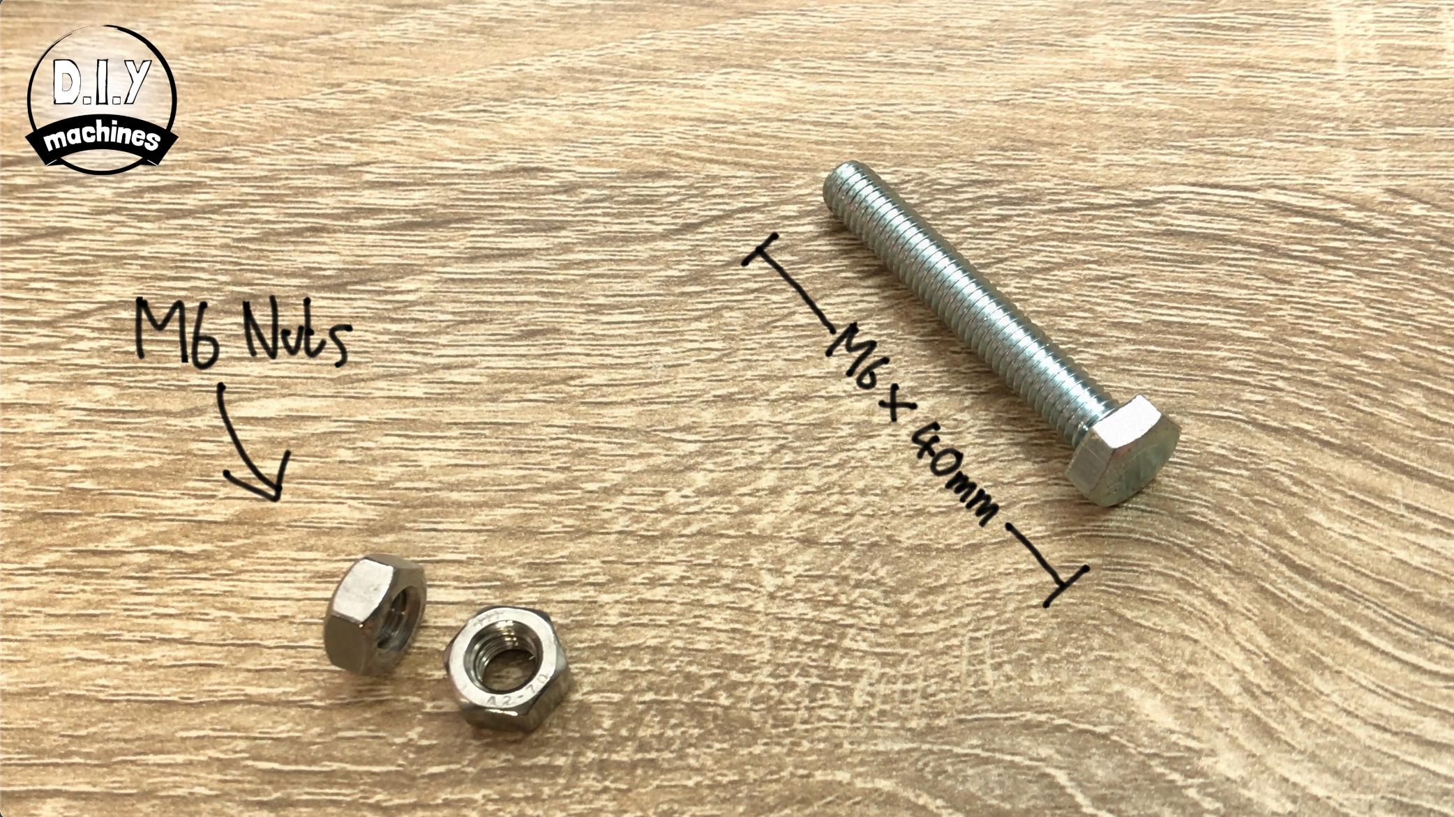
- Long M6 bolt (I used a 40mm one)
- M6 nuts (x2)
- 3D printed limit lever
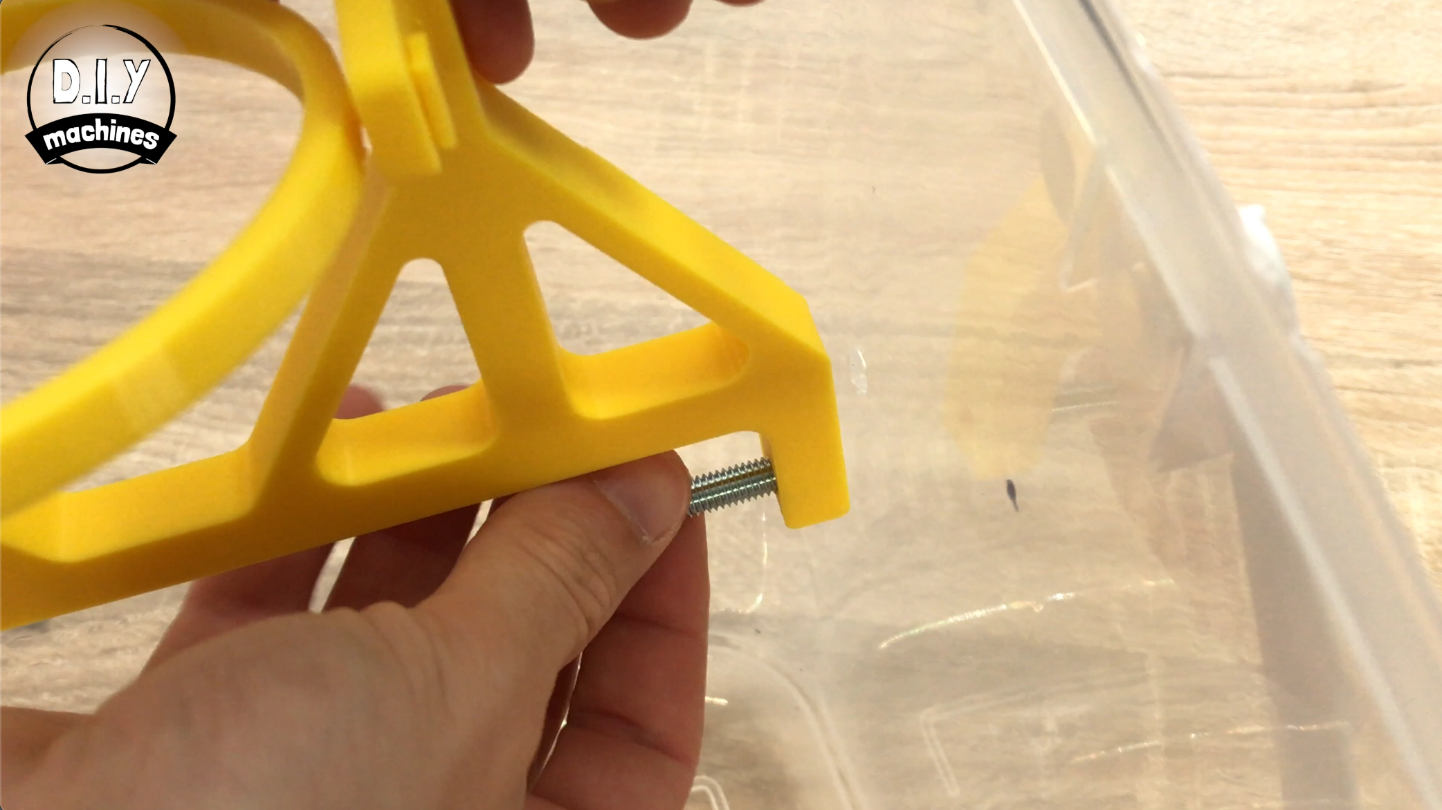
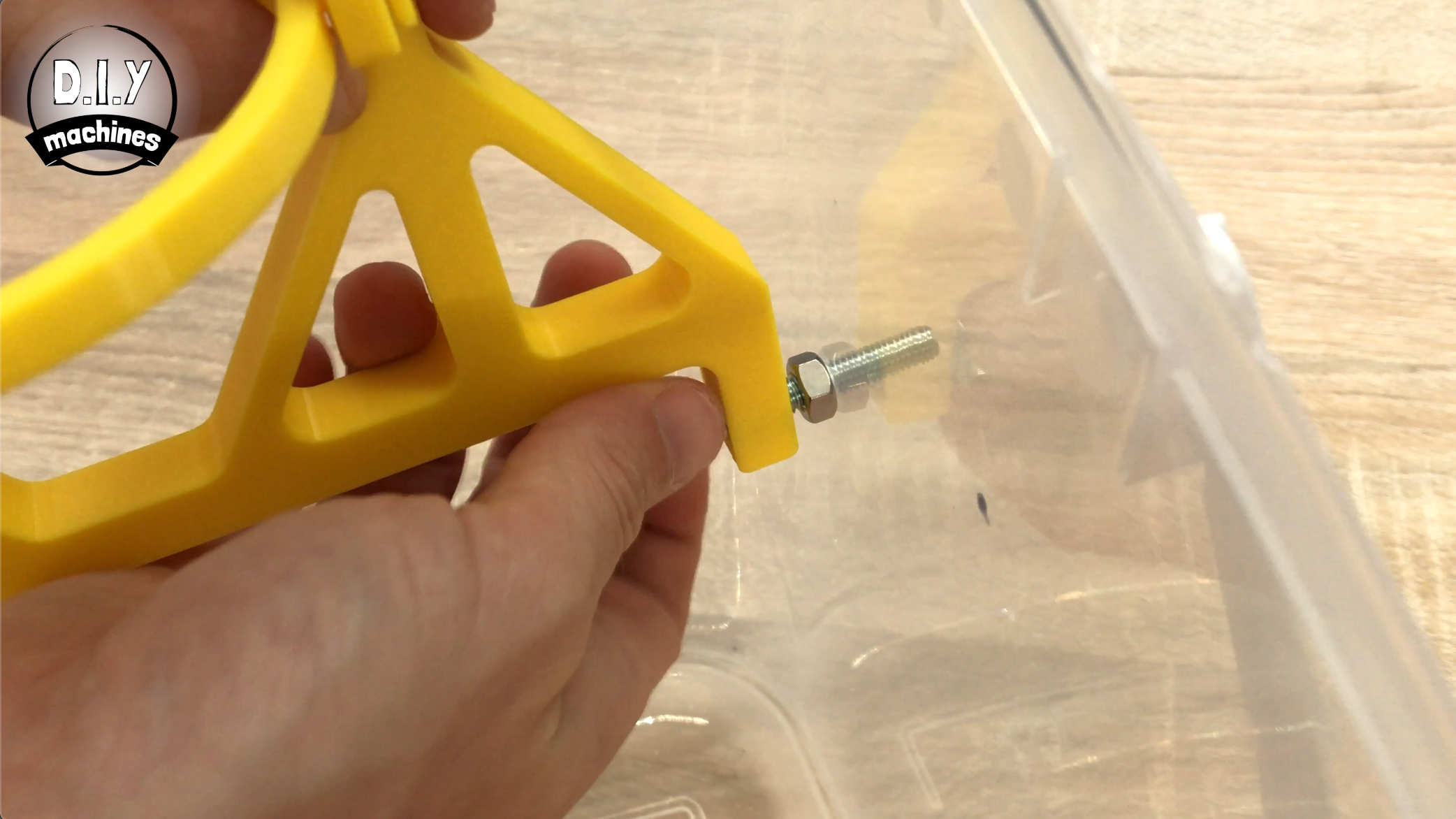
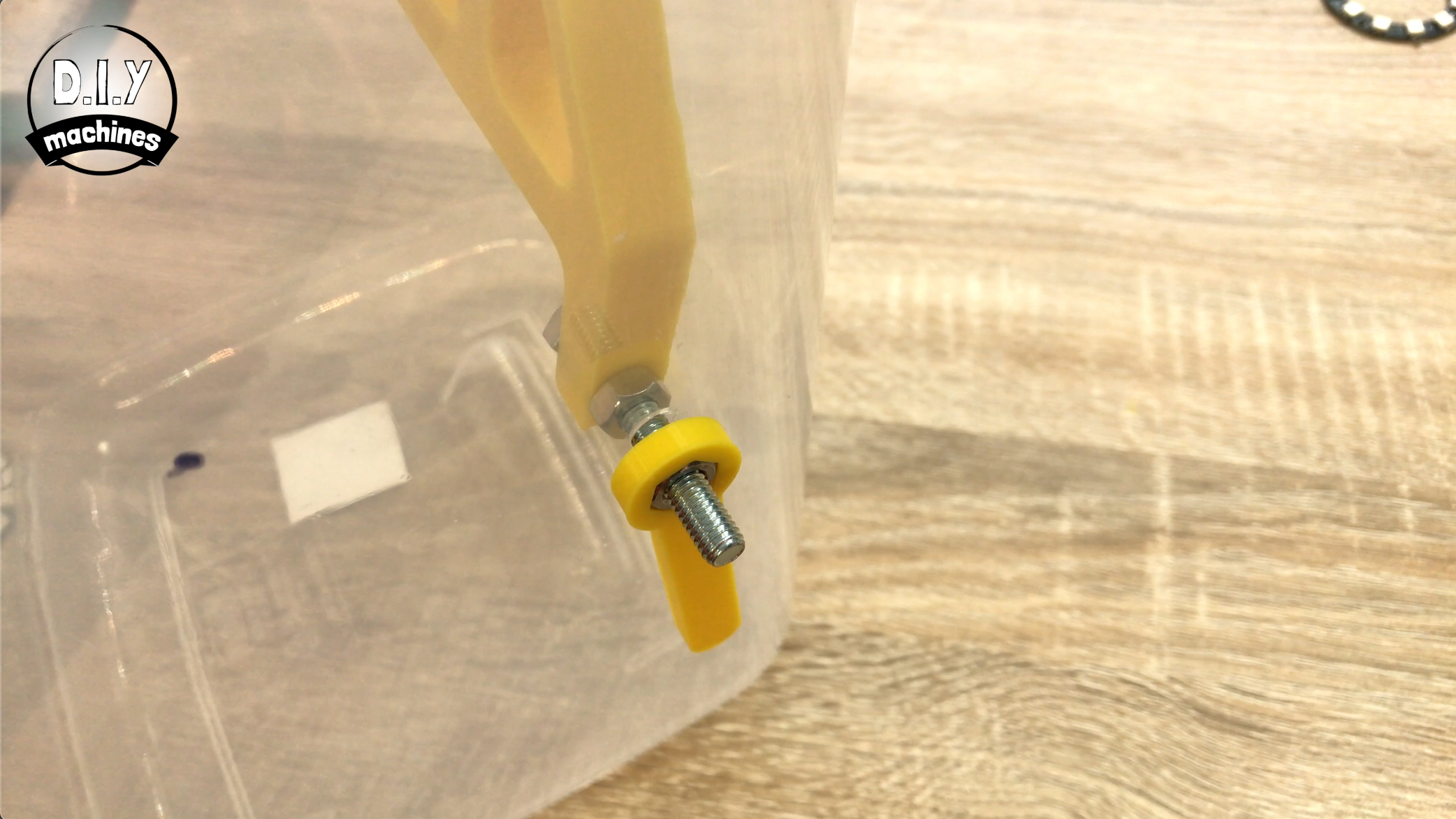
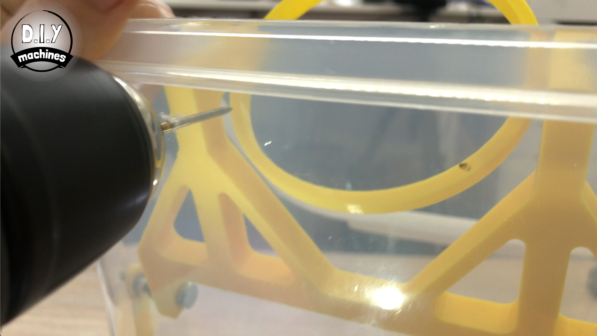
Take the long M6 bolt and screw it though from the inside of the bucket arm until the thread appears on the outside, then introduce one of the M6 nuts to the bolt before continue to screw it through the 3D print and this nut until it has passed as far as it can through the print and out through the main plastic container. (Check the image above if you are not entirely sure of what I am trying to explain).
We can now take the 3D printed 'limit lever' and secure the remaining M6 nut inside of it. For the time being you can screw this onto the end of the M6 nut where it protrudes out through the container. We will do some more to this a bit later.
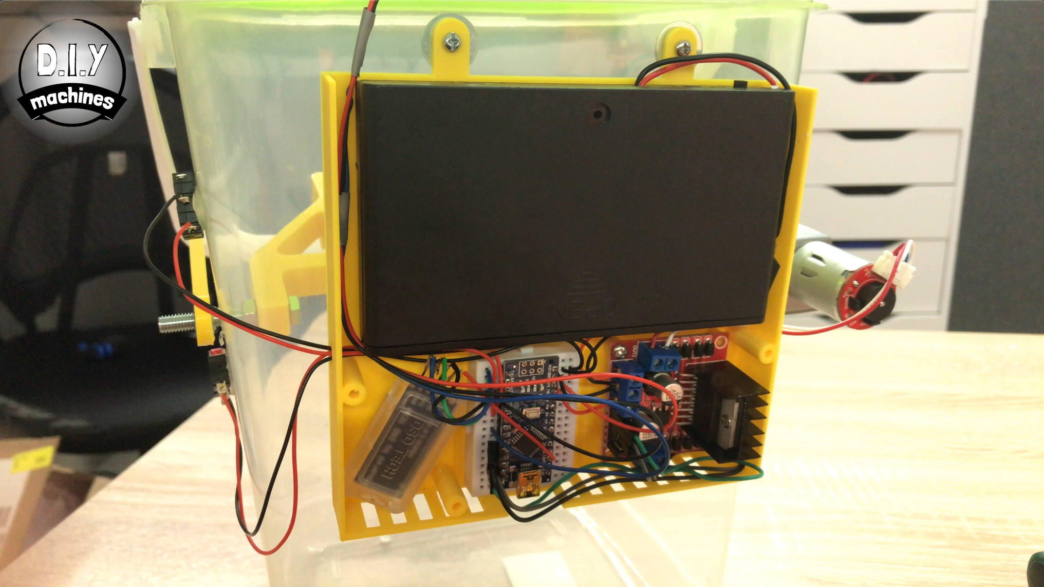
Step 7: Mount Motor Driver
For this step you will need:
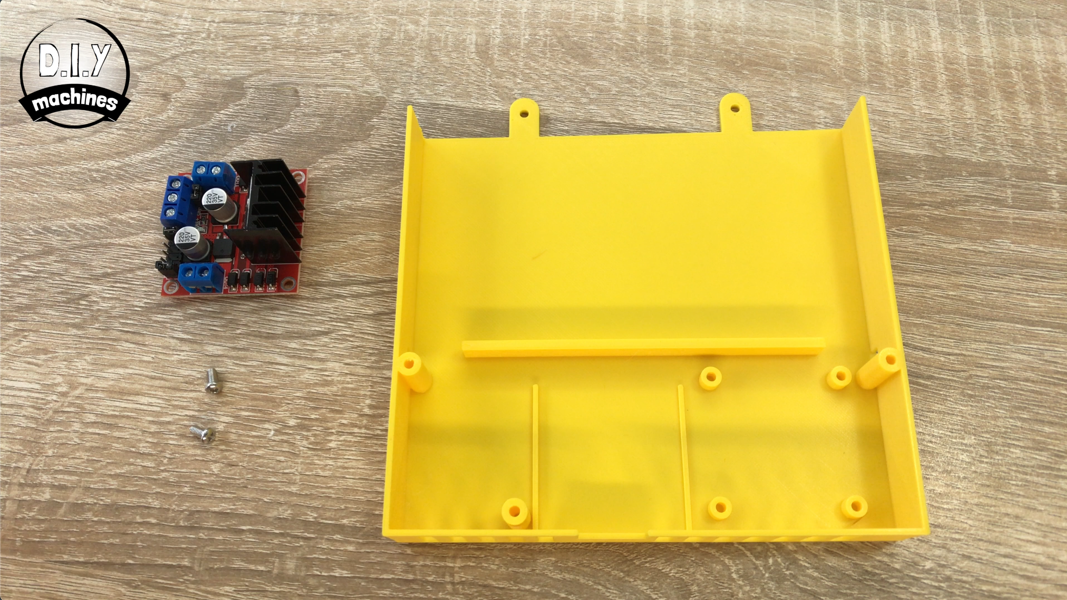
- the 3D printed housing for the electronics
- the L298N motor driver board
- at least two M3 x 6 bolts
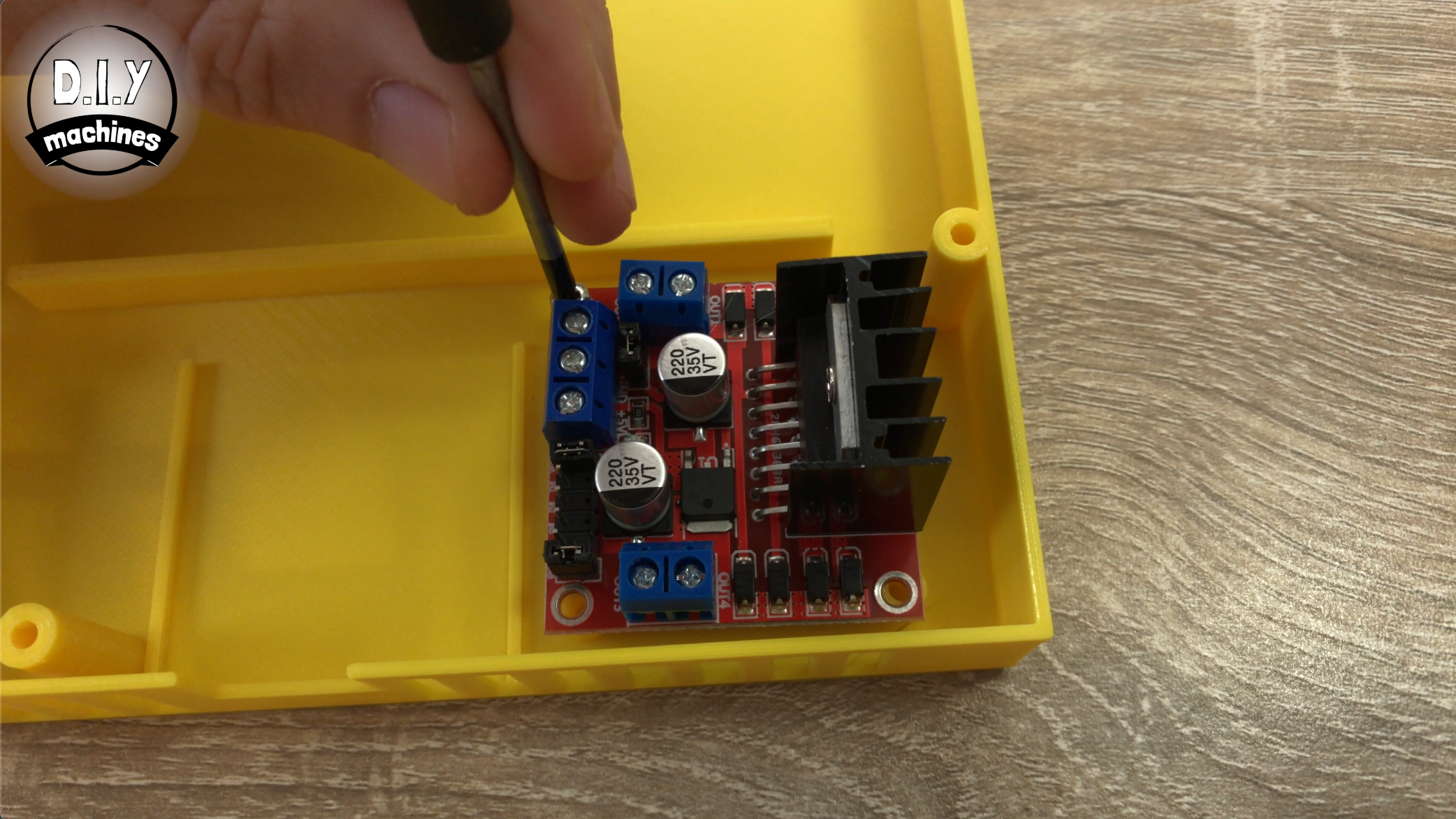
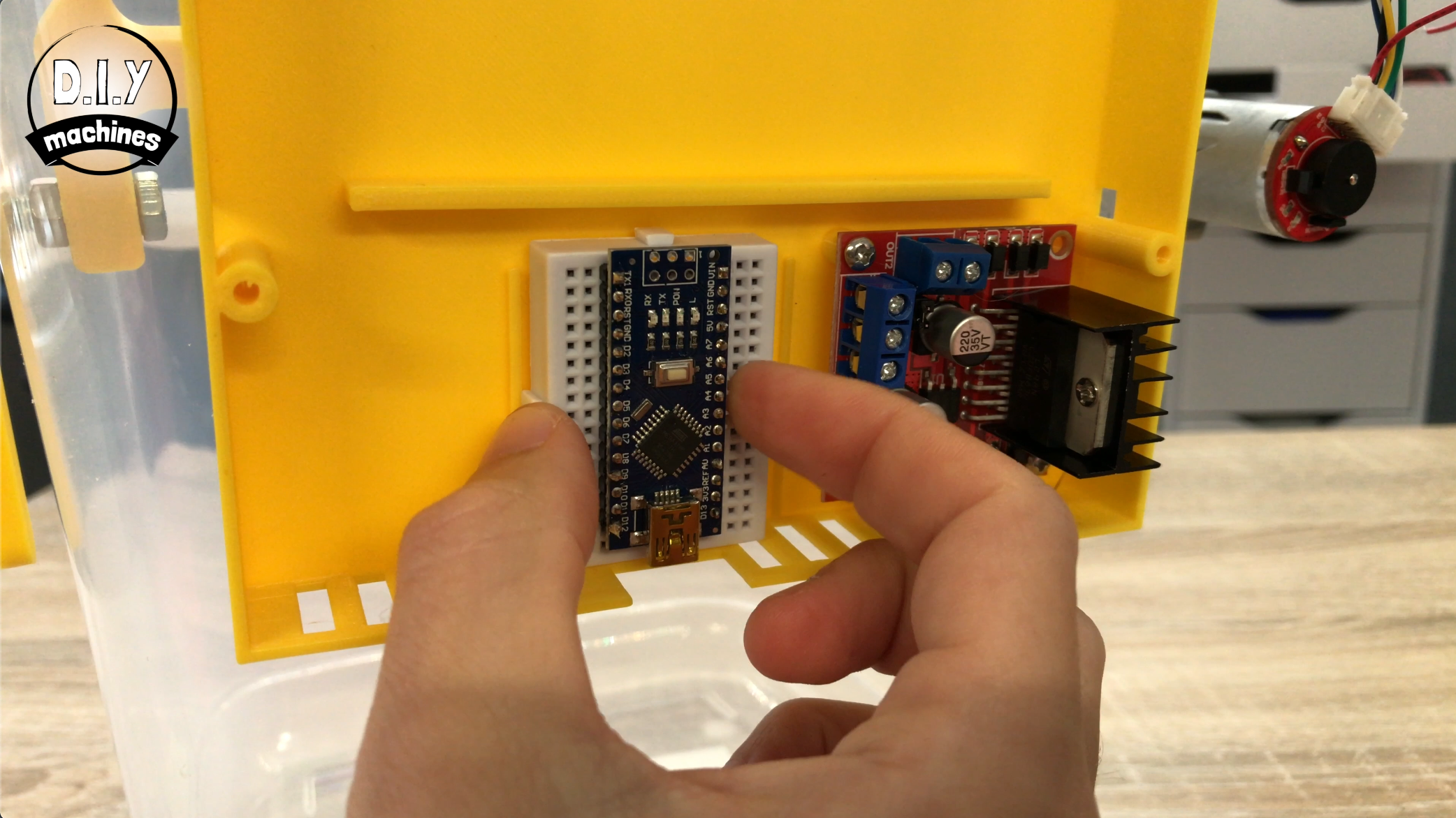
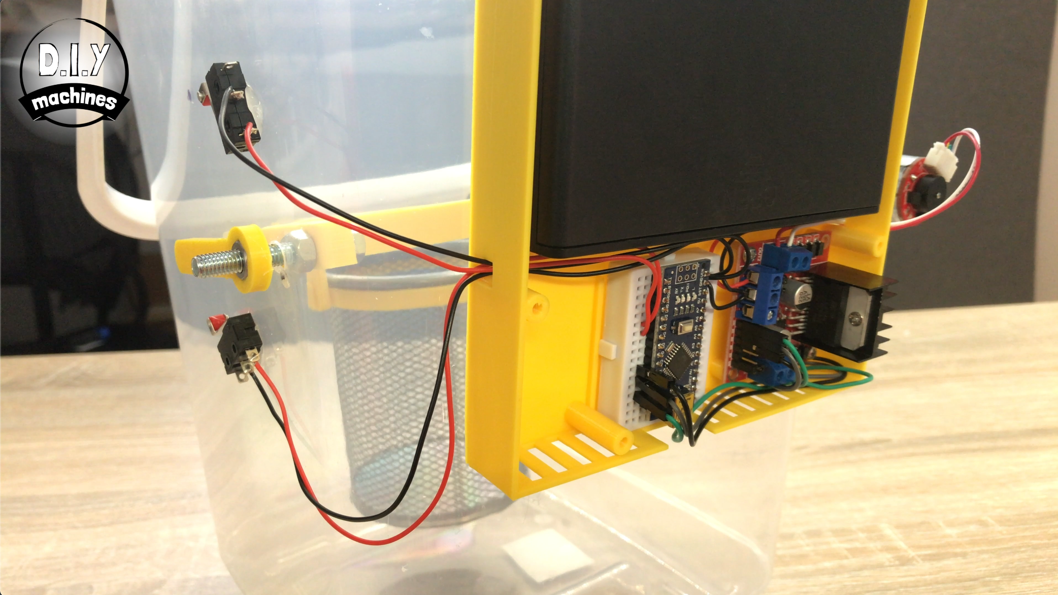
Place the motor driver board over the four raised stand offs in the lower right of the electronics housing and then secure it with at least two bolts using the holes in the four corners.If you match the orientation of yours and mine as shown in the photos it will be easier to follow this guide. It's also important as the lid is designed to accommodate the motor driver in this orientation only.
Step 8: Mount the Electronics Housing
For this step prepare:
- 3mm drill bit
- Marker pen
- M3 x 6 bolts (x2)
- M3 washer (x2)
- M3 nut (x2)
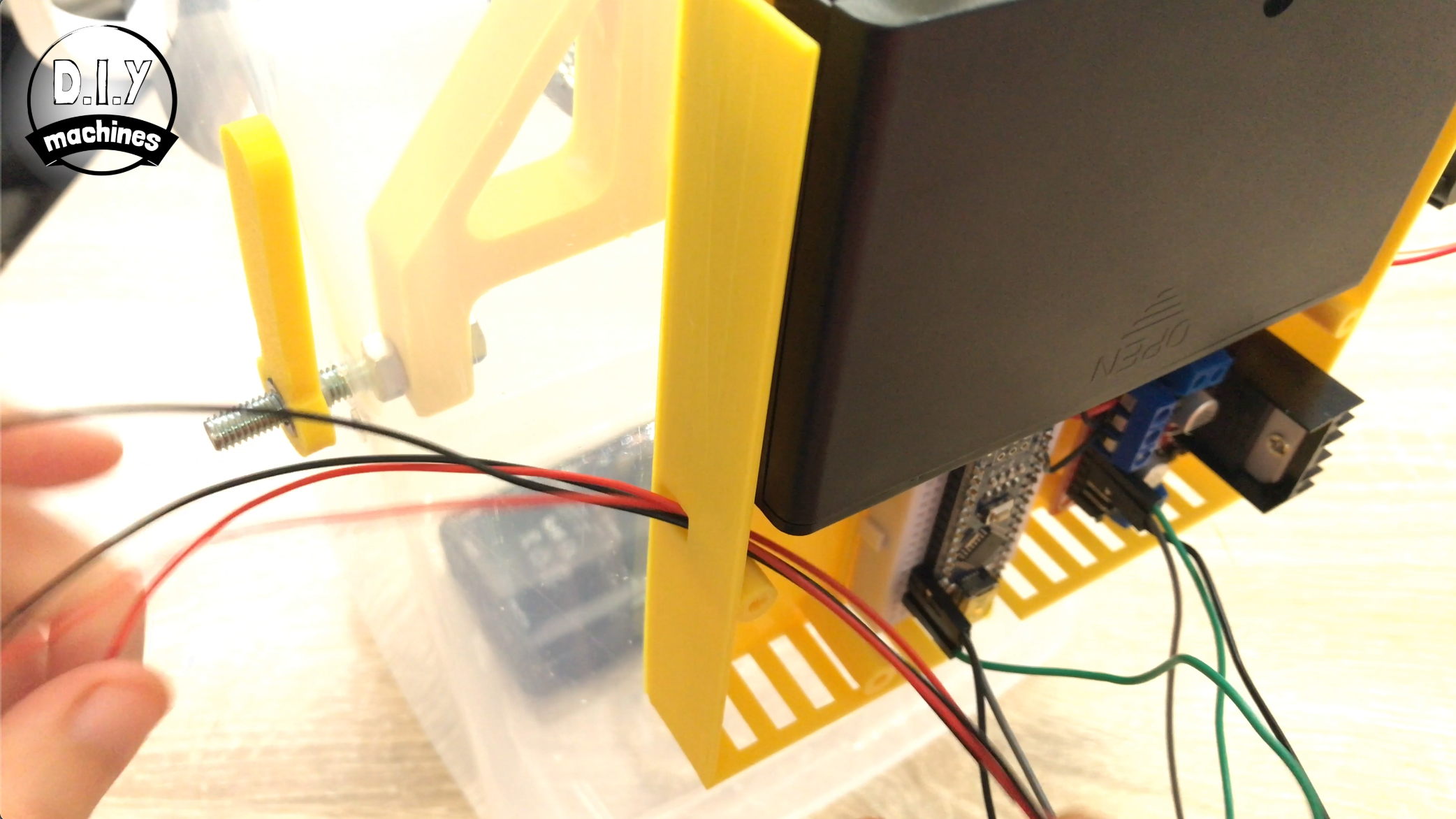
Offer up the electronics housing (the part we just added the motor driver to) to the back of the container near the top. Using a pen, mark where we need to drill two holes to mount it through the tabs at the top.
Drill these two marked point with a 3mm drill bit.
Use two M3 x 6 bolts, two M3 washers and two M3 nuts to secure this in place using the wholes we just created.
Step 9: Prepare the Arduino

For this step you'll need:
- Arduino Nano
- Self adhesive mini breadboard
- USB Cable
- Arduino IDE on a PC
- Code for the project which can be downloaded from here:
https://diymachines.co.uk/projects/bluetooth-contr...
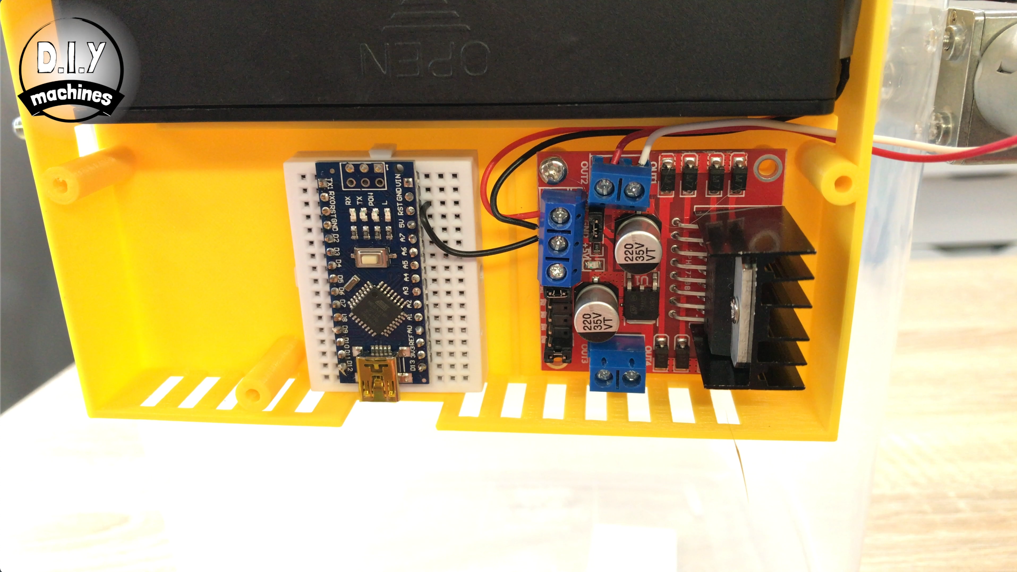
Mount the Arduino onto the breadboard. You can't mount it centrally but this is fine, position it so that the side with the 5V connection on it has three spare holes on the breadboard and that the other side has two spare holes.
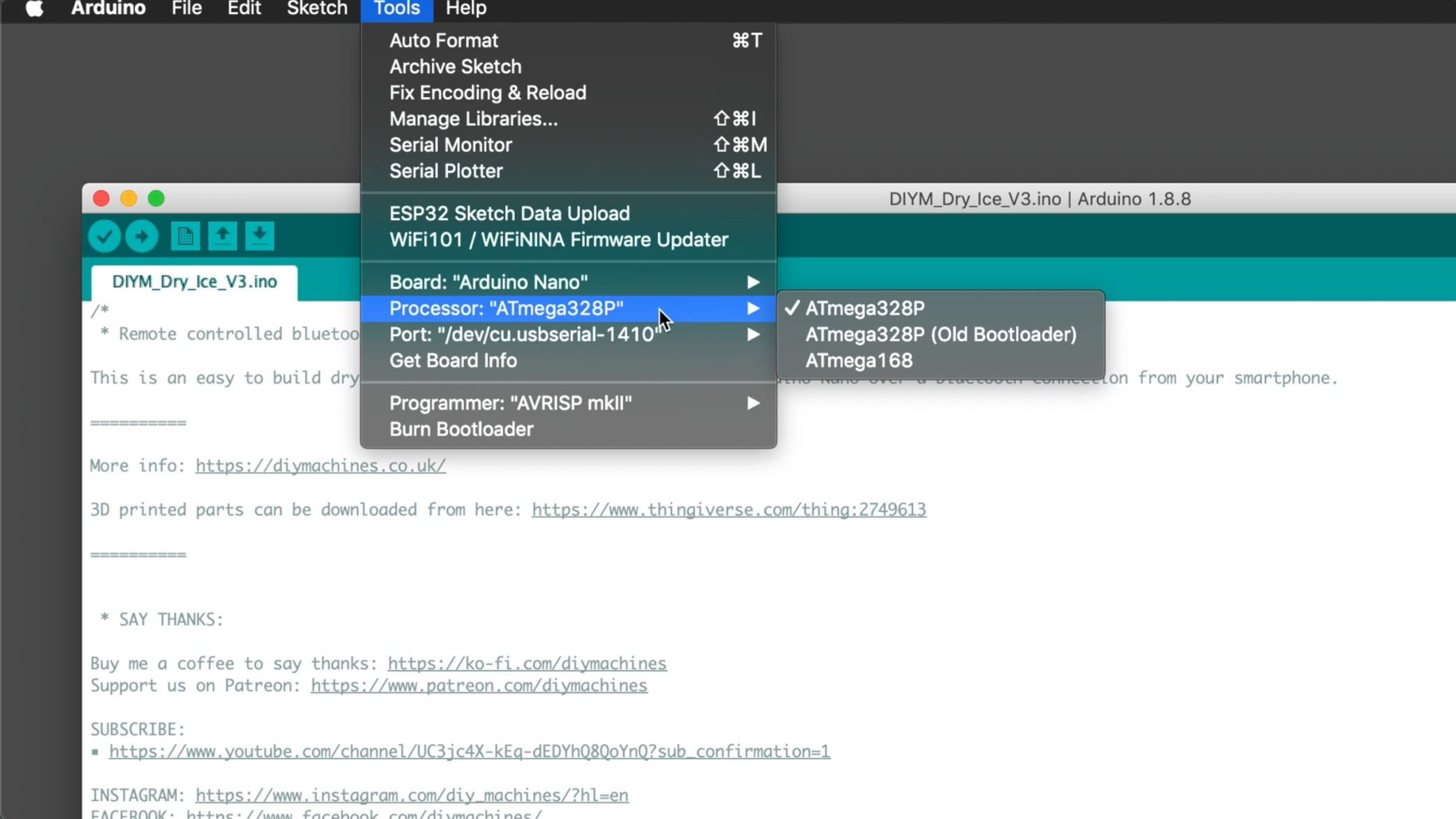
Open the code for the project in the Arduino IDE, ensure that you have the board type 'Arduino Nano' selected. the processor is an 'ATmega328P', and check you have the right serial connection.
Now you can upload your code to the Arduino Nano. Once this is done, remove the USB cable from the Arduino.
Peel off of the self-adhesive backing and push it into place centred at the bottom of the electronics housing.
Step 10: Give It Some Power!
For this step prepare:
- Wires
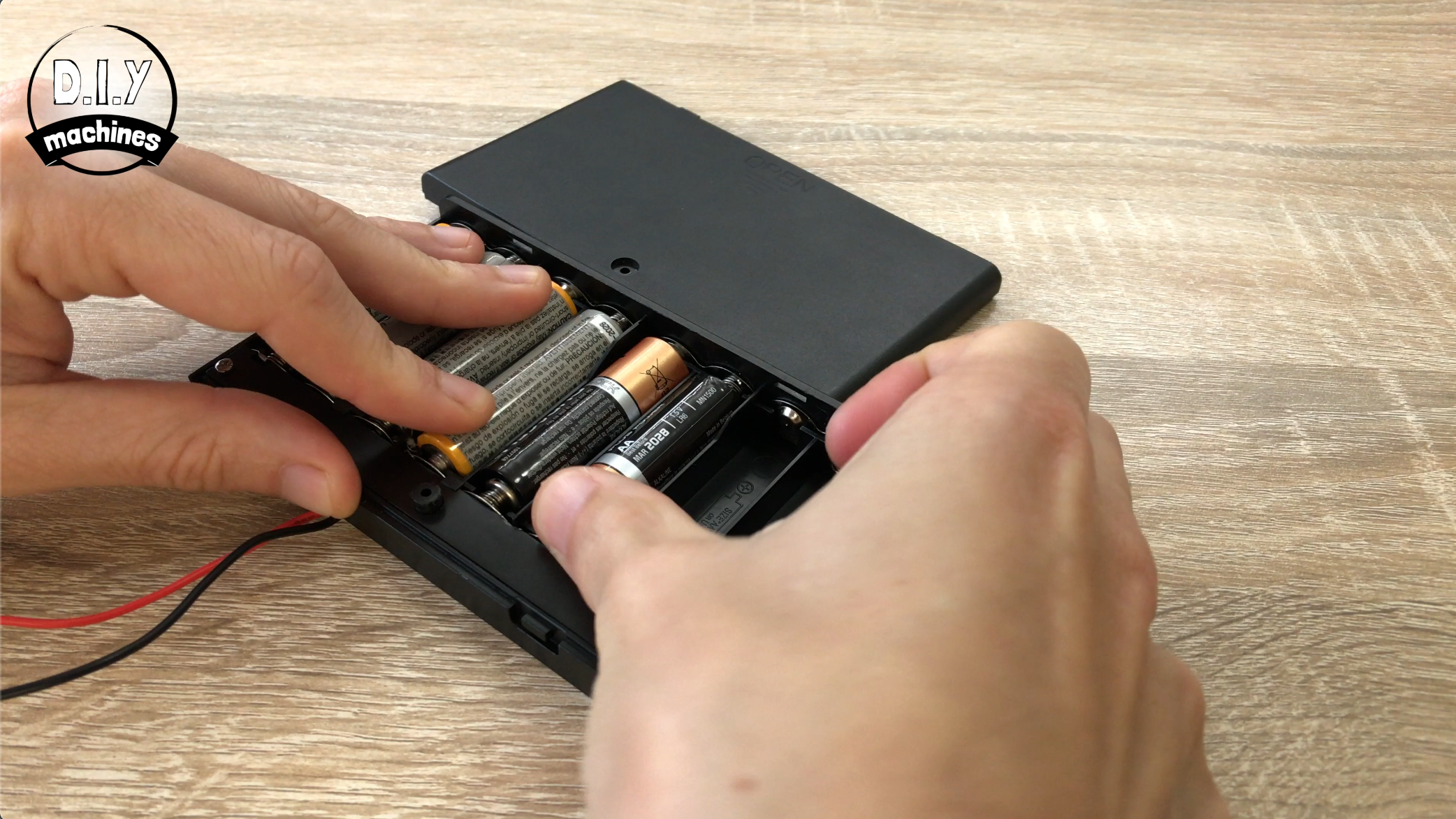
- AA batteries (x8)
- Battery holder
- Insulation tape
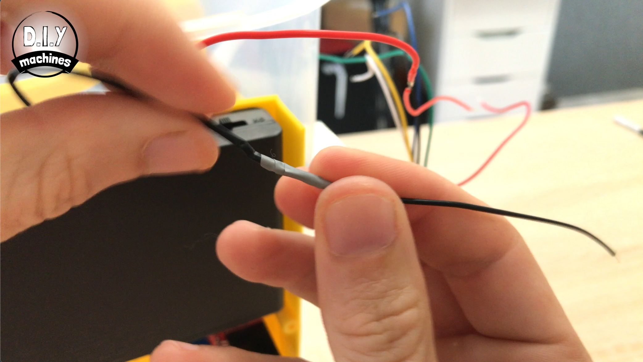
Before we can connect the battery holder we will need to extend the wires coming from it until they reach the motor driver boards terminal as shown in the first photo above. You will need to check and see how much more wire (if any) you require. I added about 7 cm to mine.
Once you have done this add the AA batteries into the holder and insulate the solder joints after you have extended the wire as we don't want the circuit to short itself.
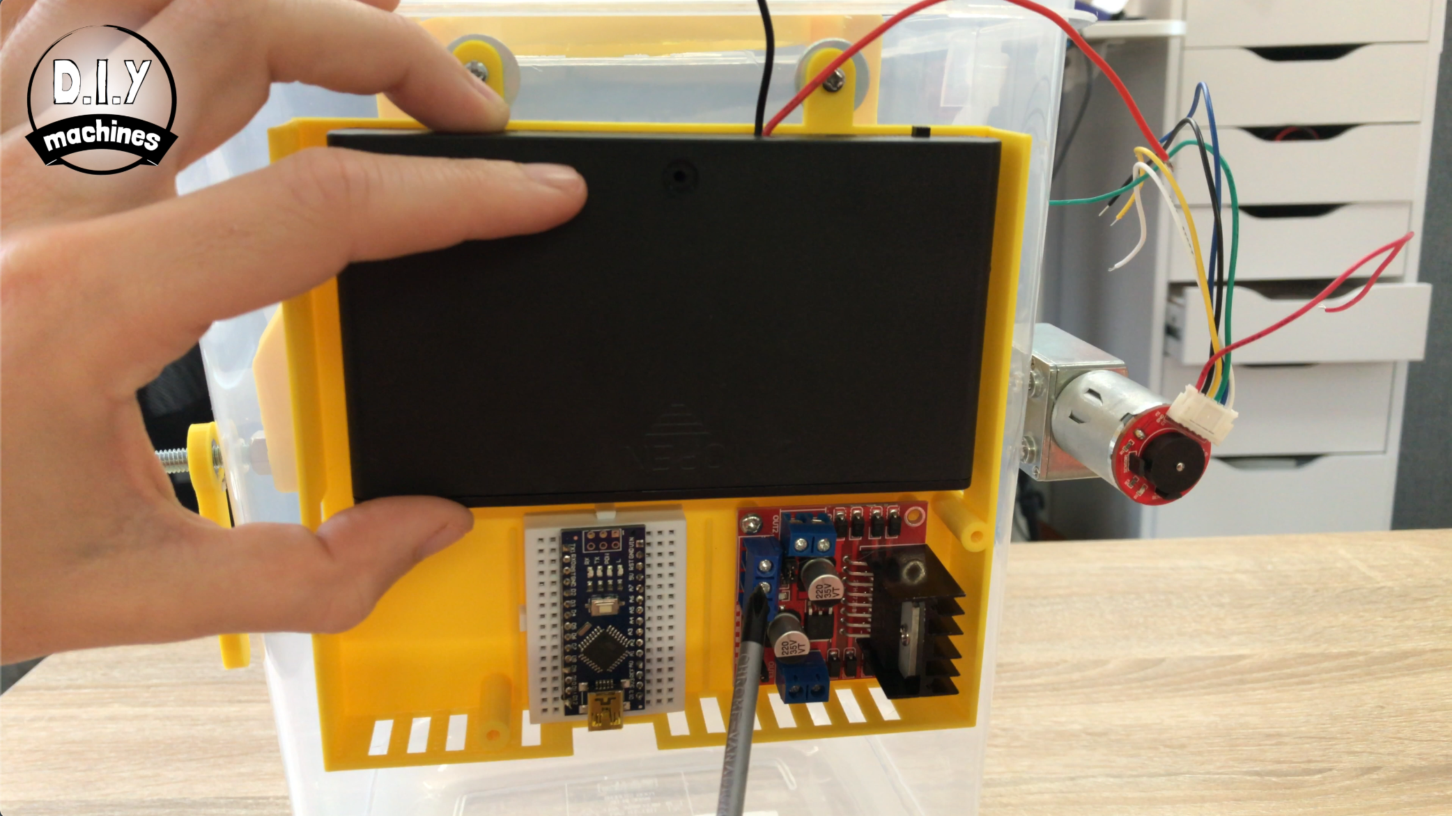
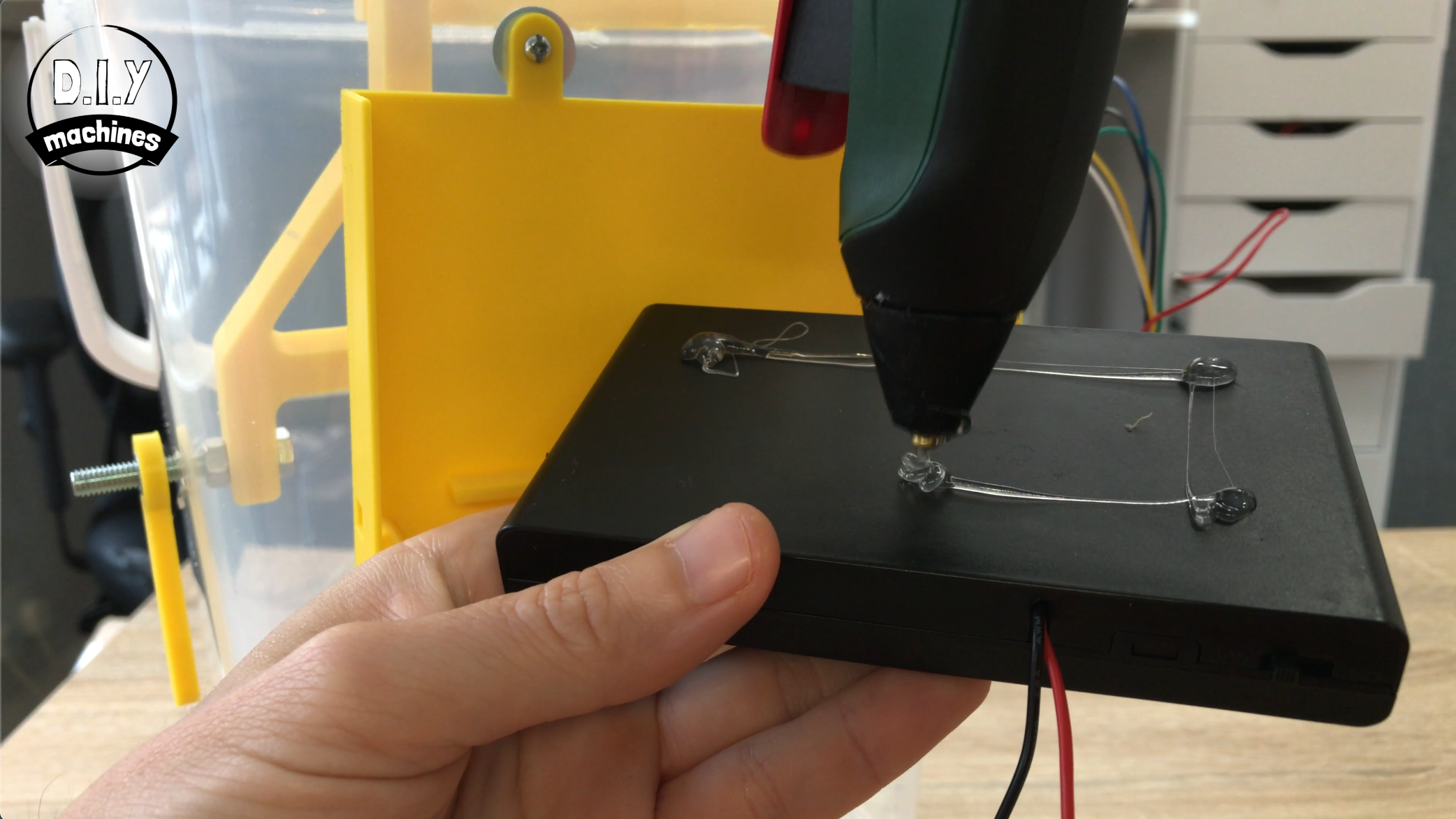
Use some hot melt glue or similar to stick the battery holder to the electronics holder. Ensure that you stick it so that you can still open the cover of the battery holder.
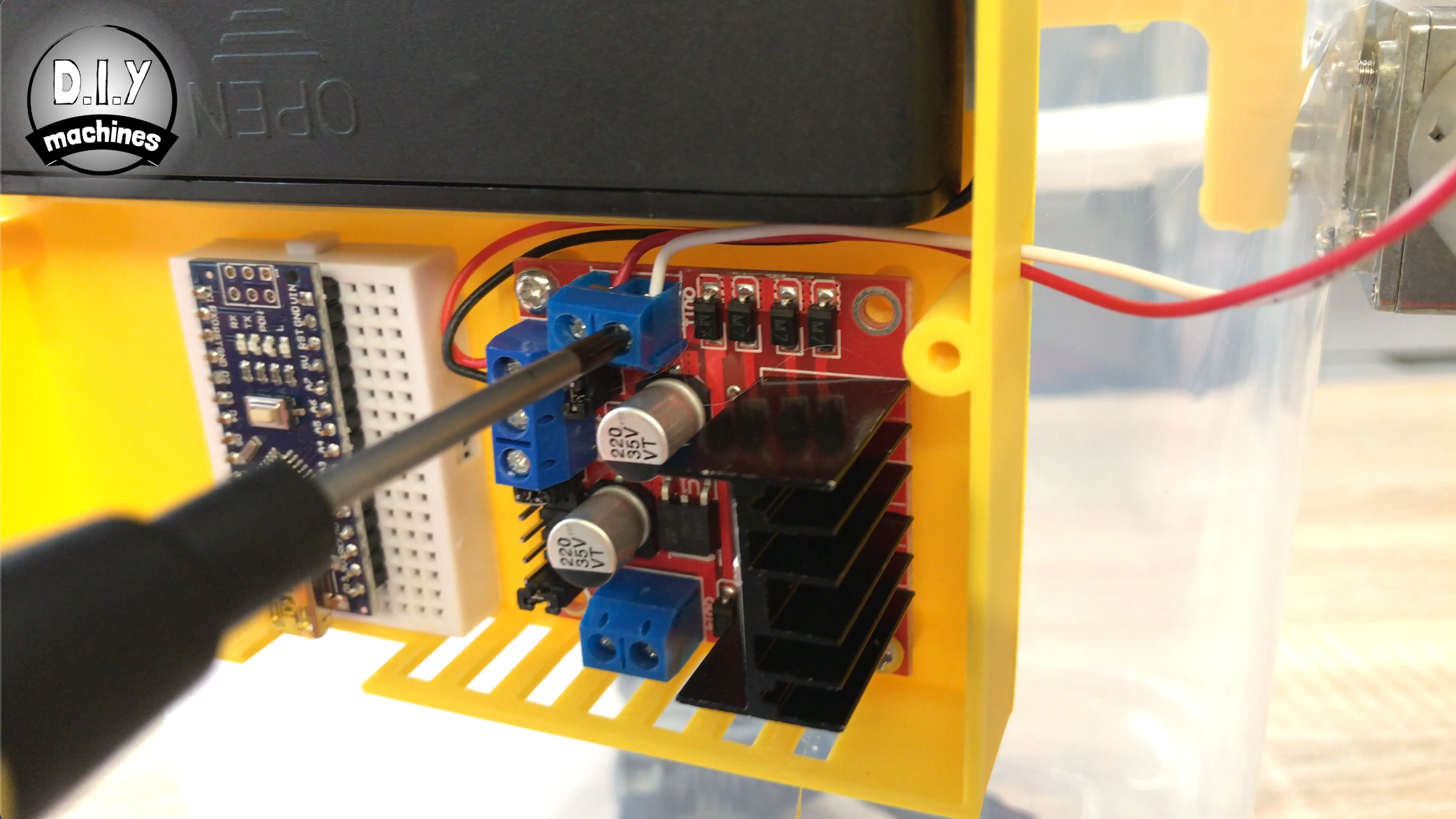
We can then take the leads down the side of the battery holder, over the top of the motor driver and insert the positive wire into the top of the three terminals on the motor driver board (VCC) and the negative into the middle of the three (ground).
Step 11: Connect the Motor
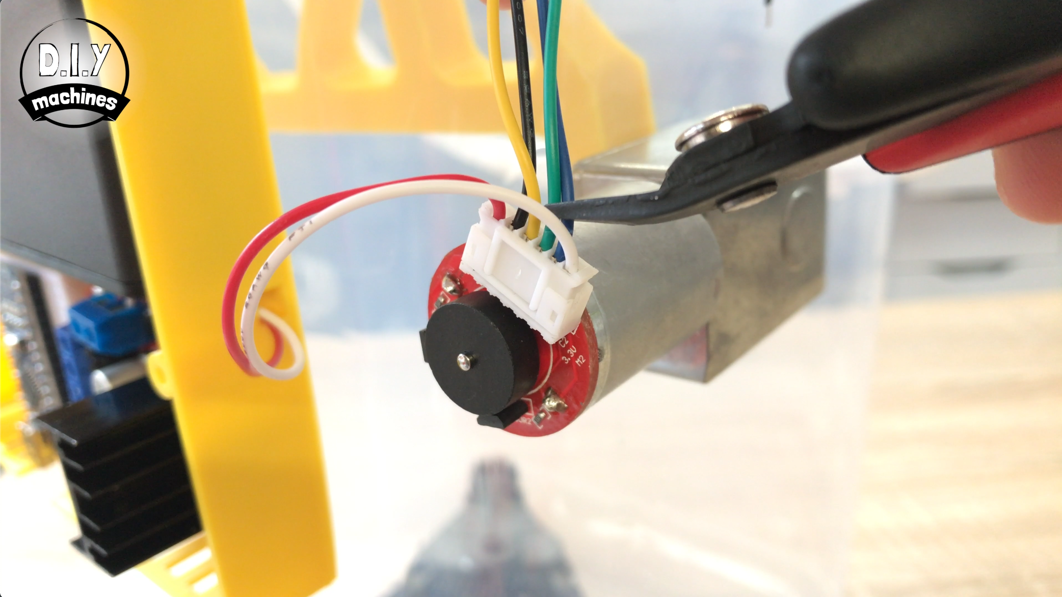
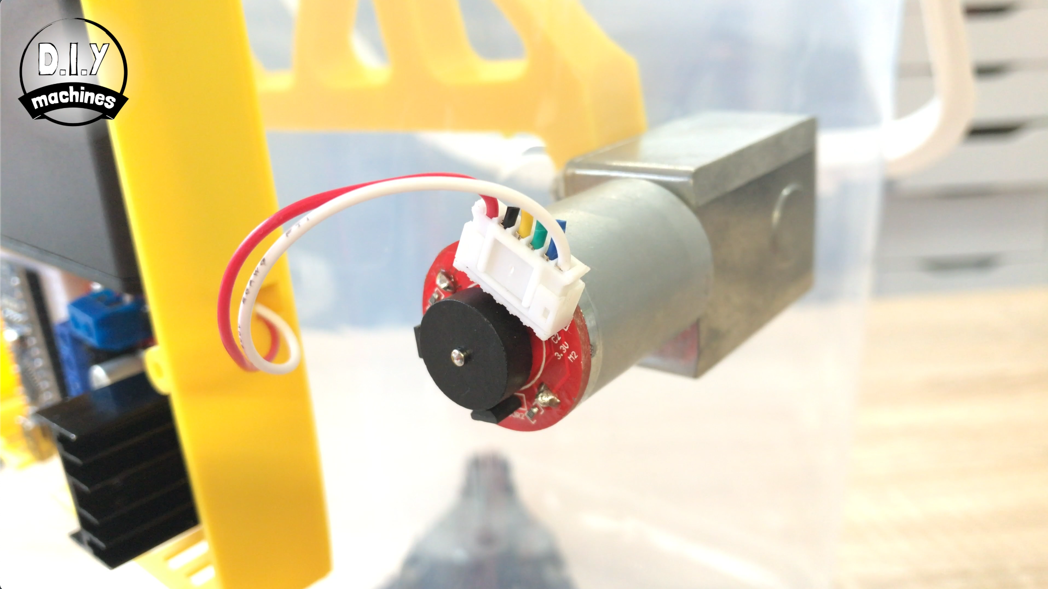
As with the power leads you might need to extend the cables coming from your motor for this next step.
The white and red leads coming from the motor are to be threaded through the hole in the side of the housing nearest the motor driver. The red wire is connected to the terminal at the top left and the white wire to the terminal top right. (This pair of connection terminals is referred to as being for 'Motor A' on the L298N).
The remaining four coloured wires are not required so can be removed if you wish.
Step 12: Connect Arduino and Motor Driver
For this step prepare:
- Wires and or jumper leads
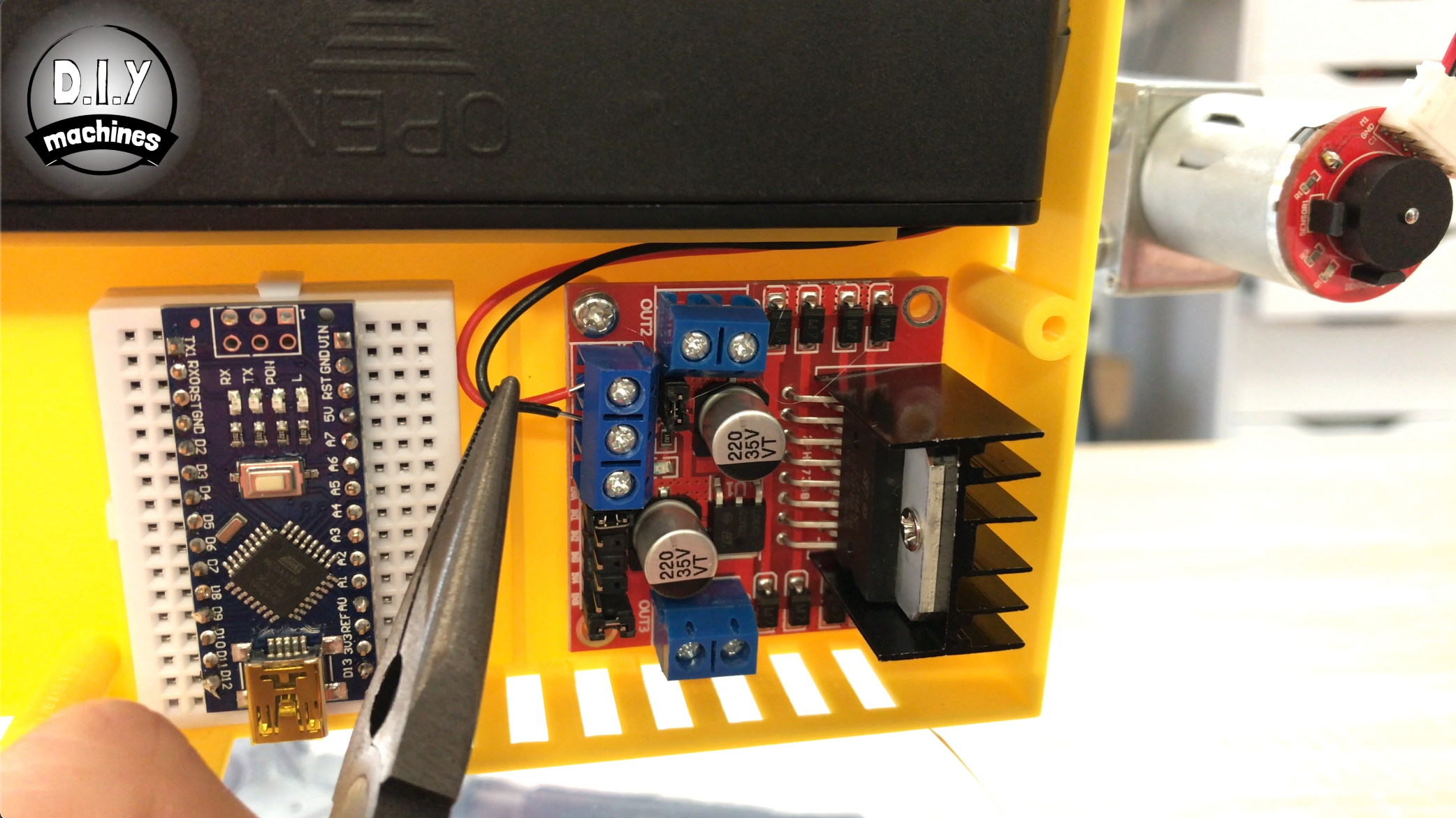
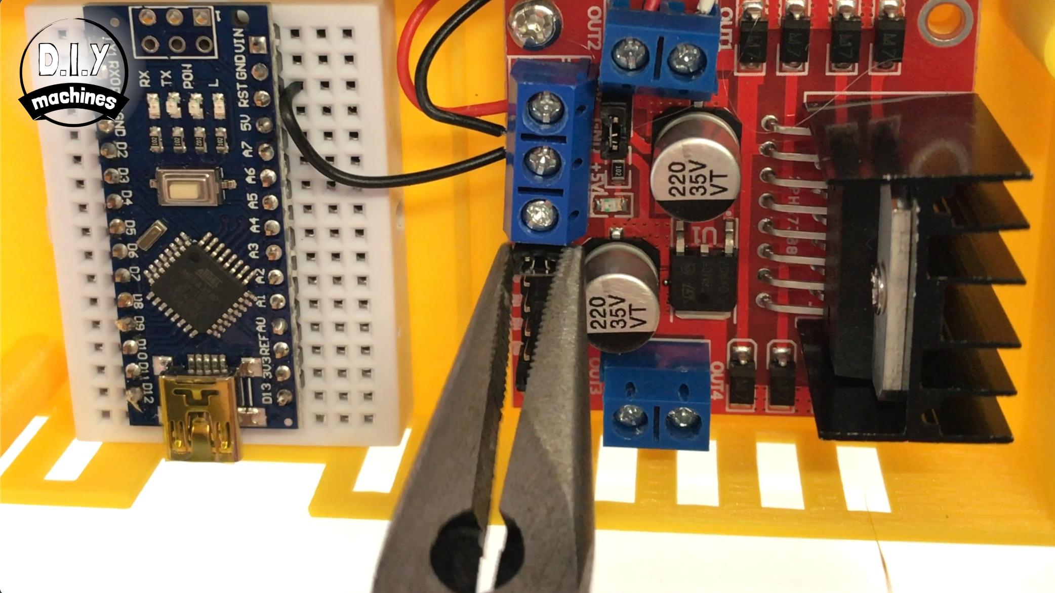
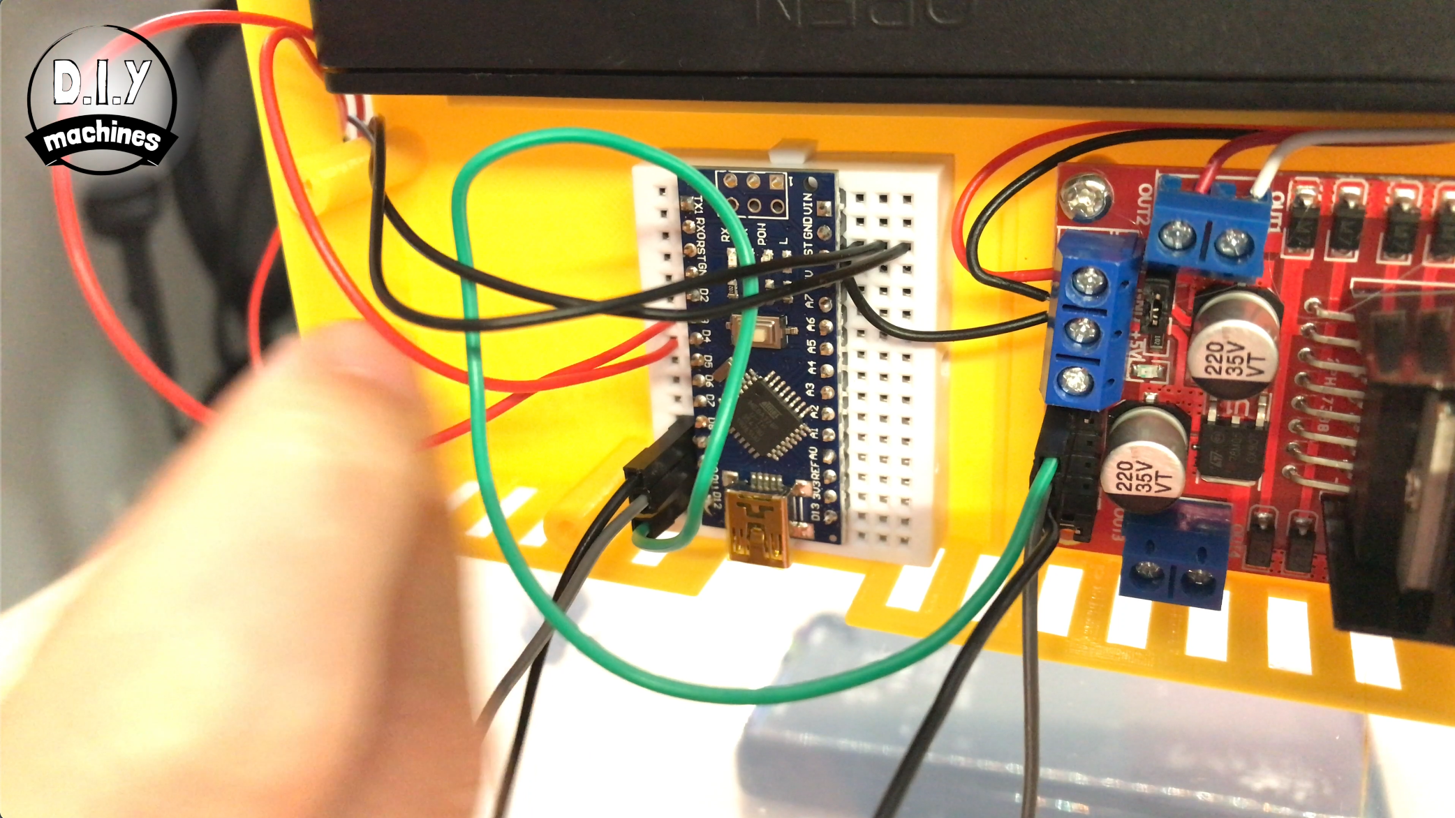
This is a very simple step. We need to connect all the grounds together so add a short length of wire between the ground terminal on the motor driver board (the same on what the battery pack is connected to) and then insert the other end of the wire to a ground terminal on the breadboard.
We can also quickly remove the jumper below the 5V connection on the motor driver.
Use a wire to join 'Enable A' from the motor shield to Digital 11 on the Arduino. From 'Input 1' on the motor shield to Digital 9 on the Arduino and finally from 'Input 2' to Digital 8 on the Arduino.
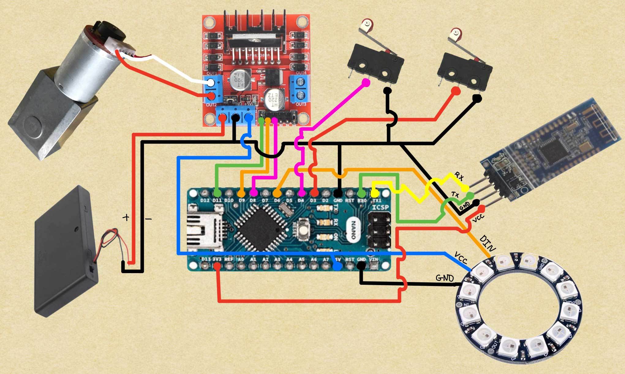
If the photo or pin names are not clear enough for you I have also attached my homemade wiring diagram. :)
Step 13: Contact Switches
For this step prepare:
- Contact switches (x2)
- Wire
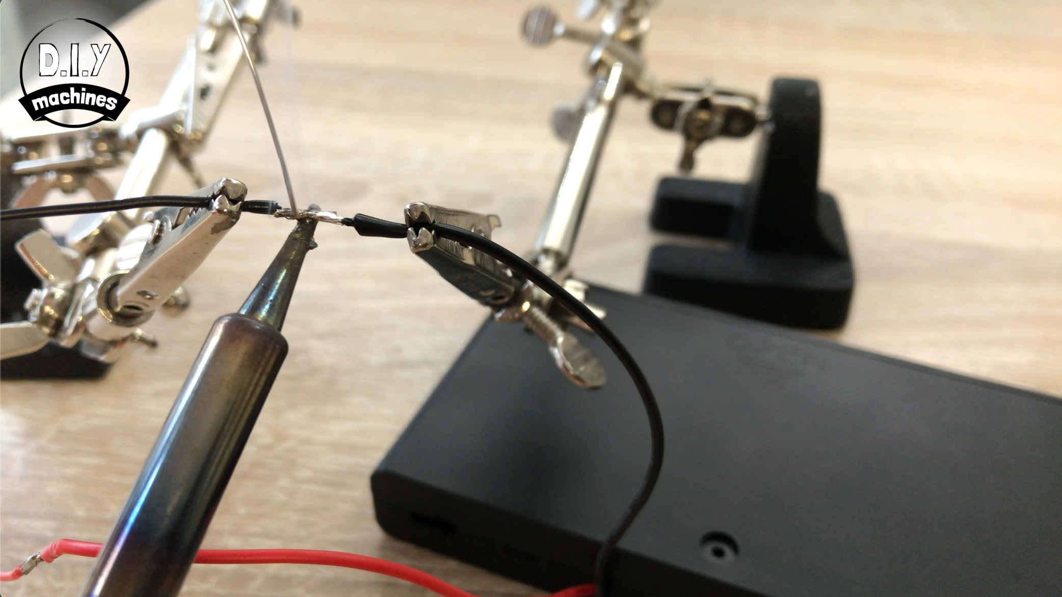
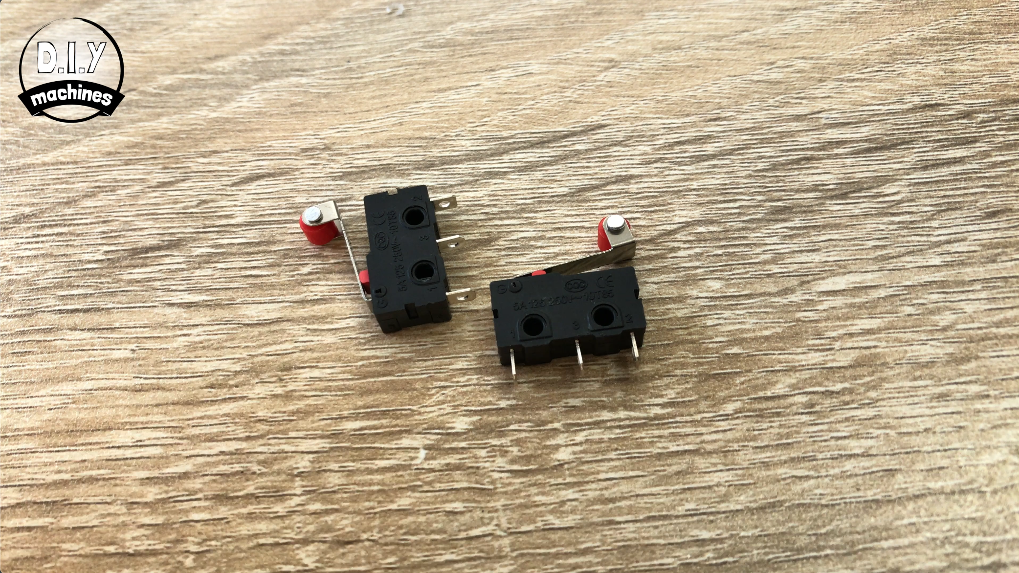
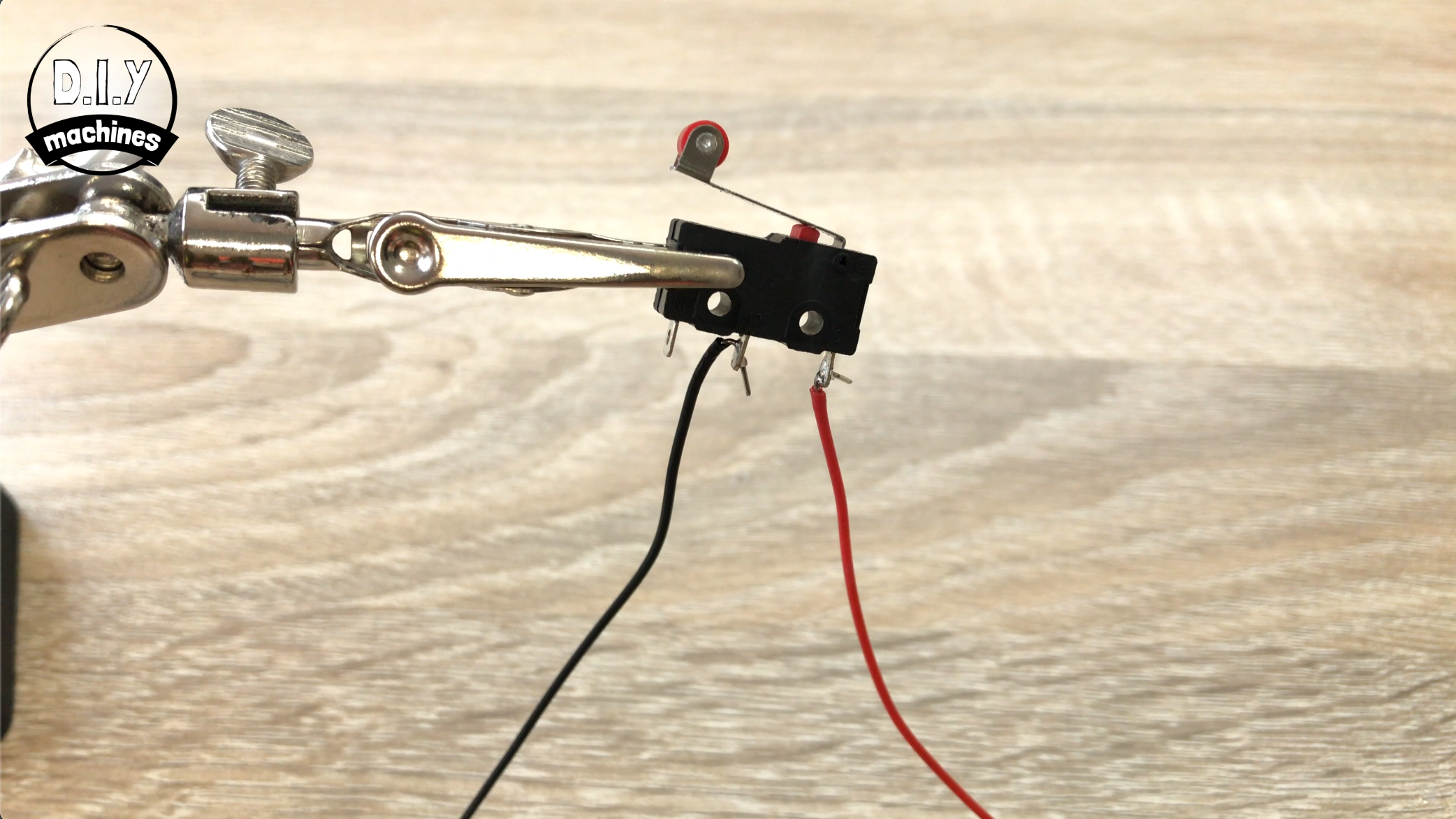
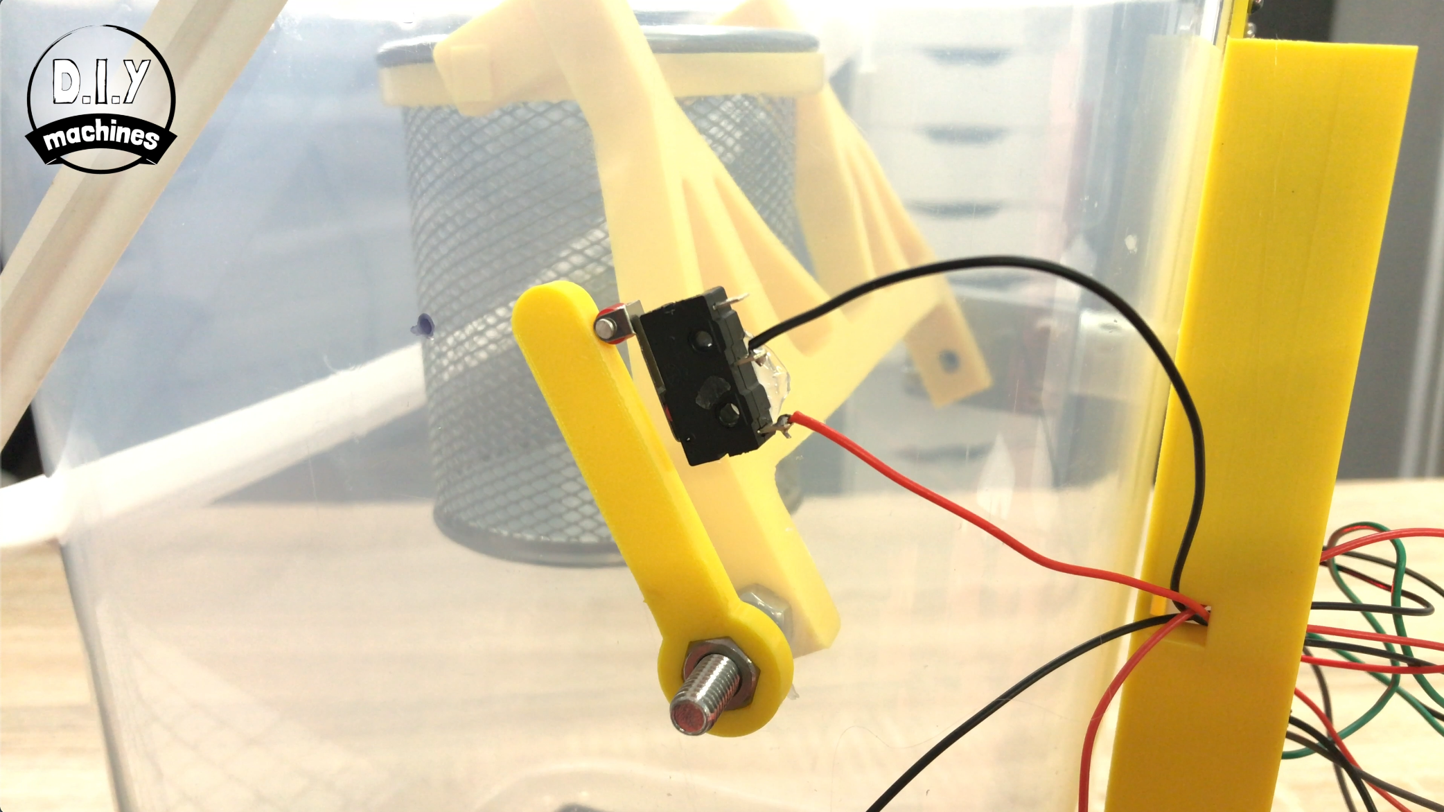
Now we need to solder some wire to our contact switches. The wire will need to be long enough to go from the contact switches final location near the 'limit lever' all the way through the casing and back to the Arduino Nano.
I made mine about 25cm each and then trimmed them to a shorter length later after everything else was in place.
The wires need to be connected to the central pin on the contact switch and the pin underneath where the contact arm meets the plastic housing - again check the photos above for clarification please.
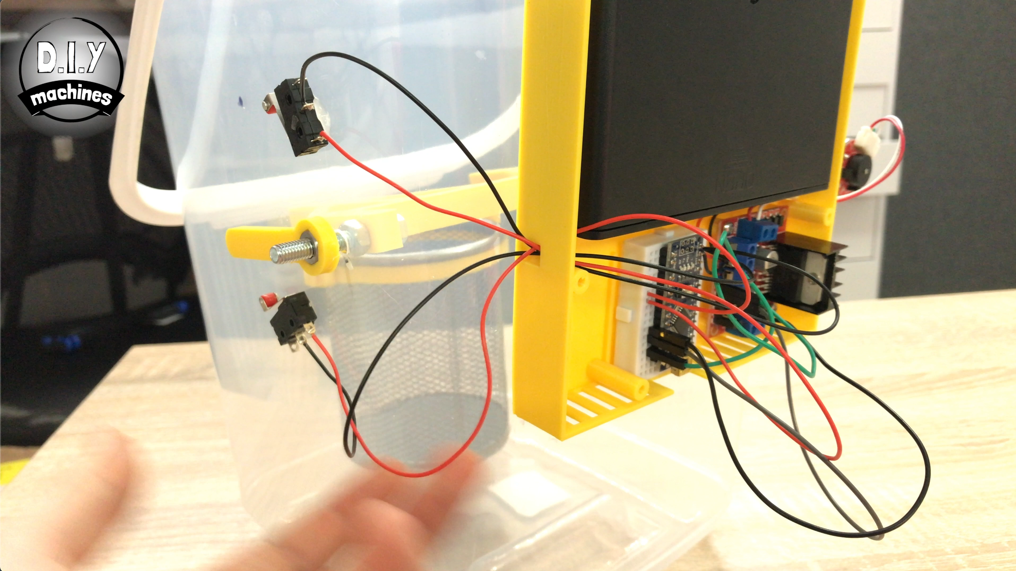
Once you have finished soldering, feed all four wires through the side of the case.
Connect one wire from each switch to ground. The remaining wire from one switch can go to Digital 3 and then the wire on the other switch can go to Digital 4.
Step 14: Calibrate the Contact Switches
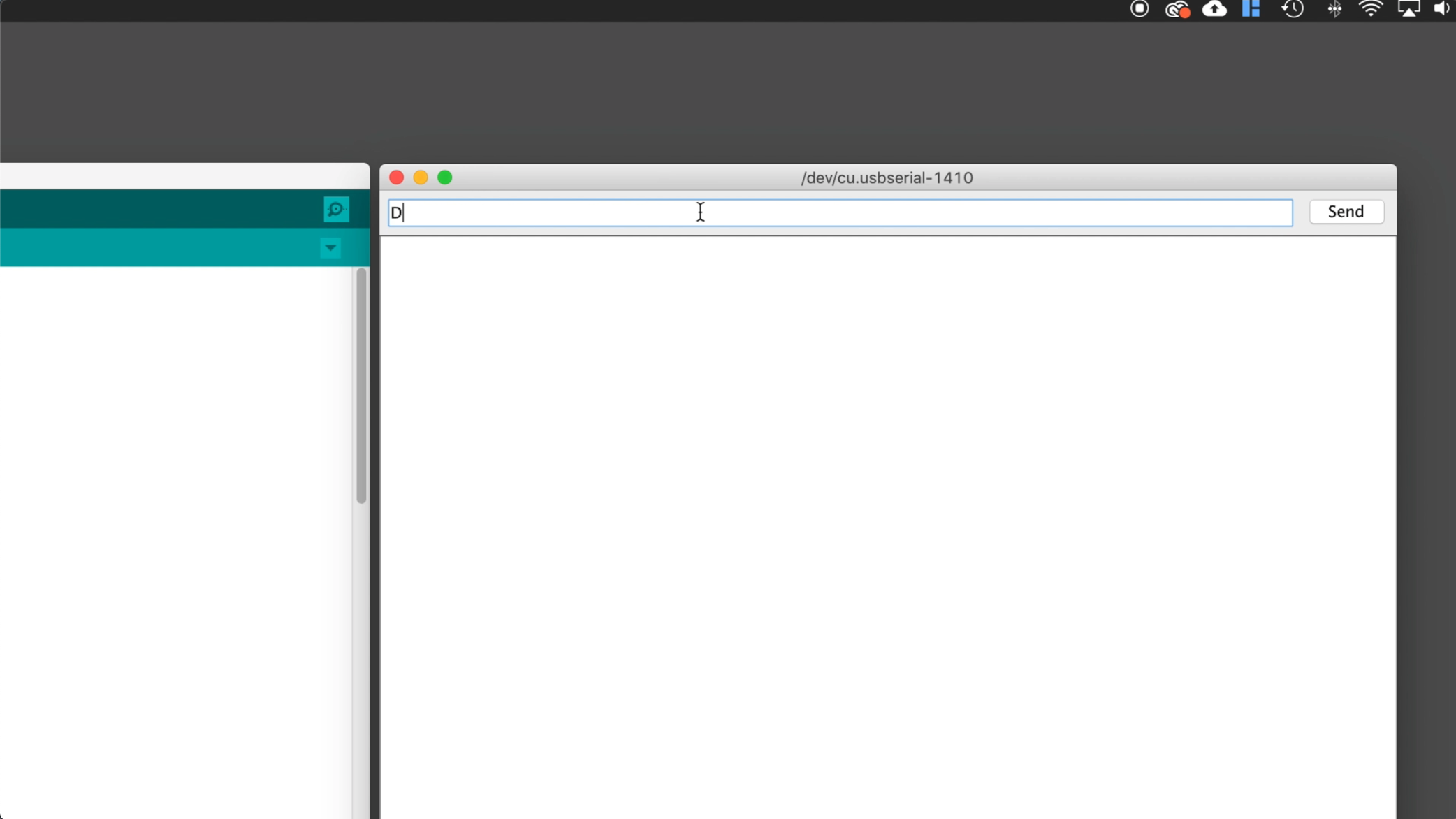
Connect your Arduino to your PC via USB again and open the Arduino IDE. Open the serial monitor and ensure that the baud rate is 9600. Now we will install our limit switches.
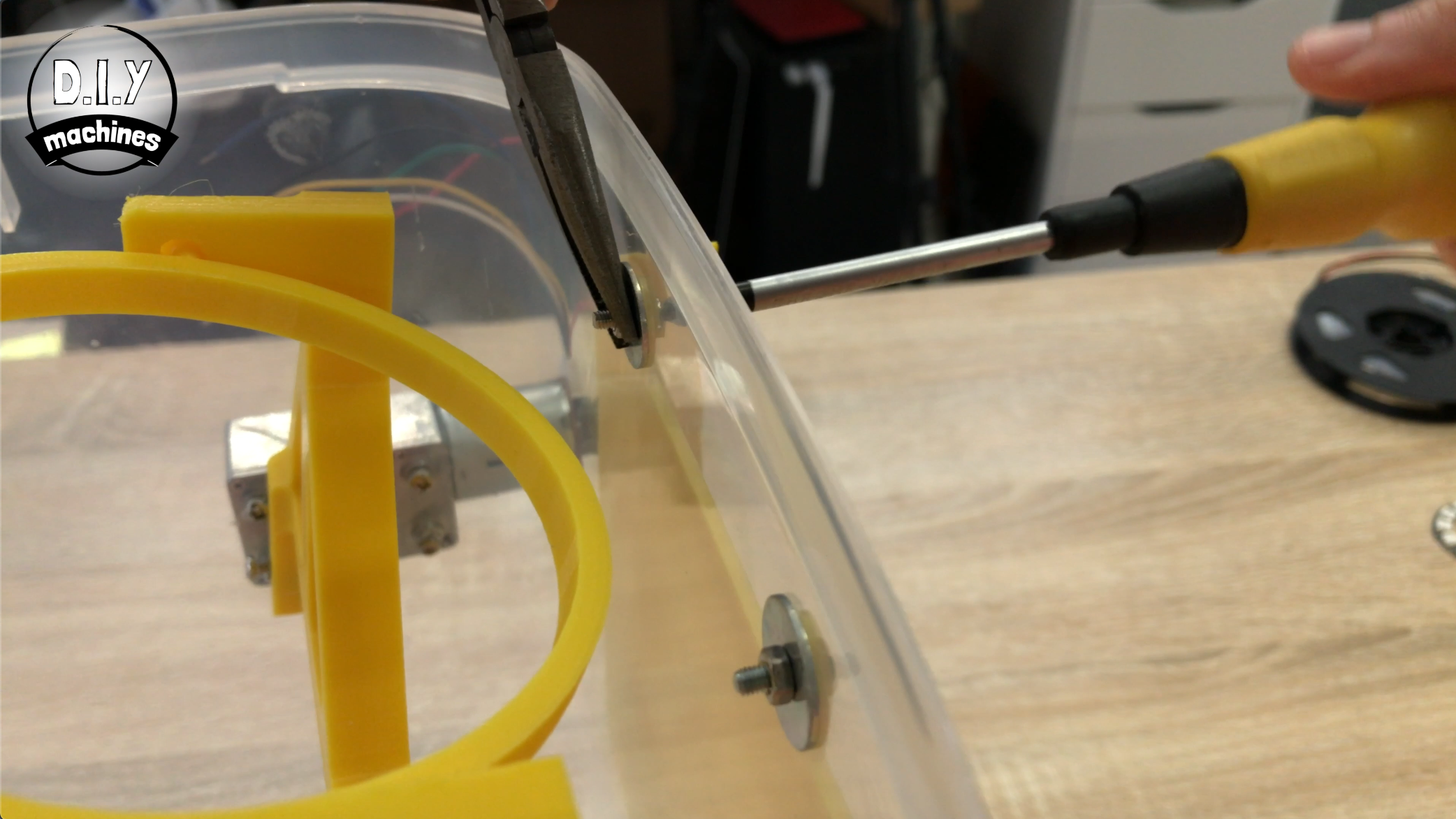
Undo the nut with the arm on slightly and apply some glue to shaft of the bolt and then screw the bolt back on ensuring that the arm sets in the same position as the 3D print inside the container.
Switch on the power coming from your AA batteries.
Now with the stationary holder back in place inside your 3D printed part we can send a capital 'D' through the Arduino serial monitor to lower the arm slightly. You want to continue to lower it until the stationary holder can swivel freely without hitting the 3D printed parts.
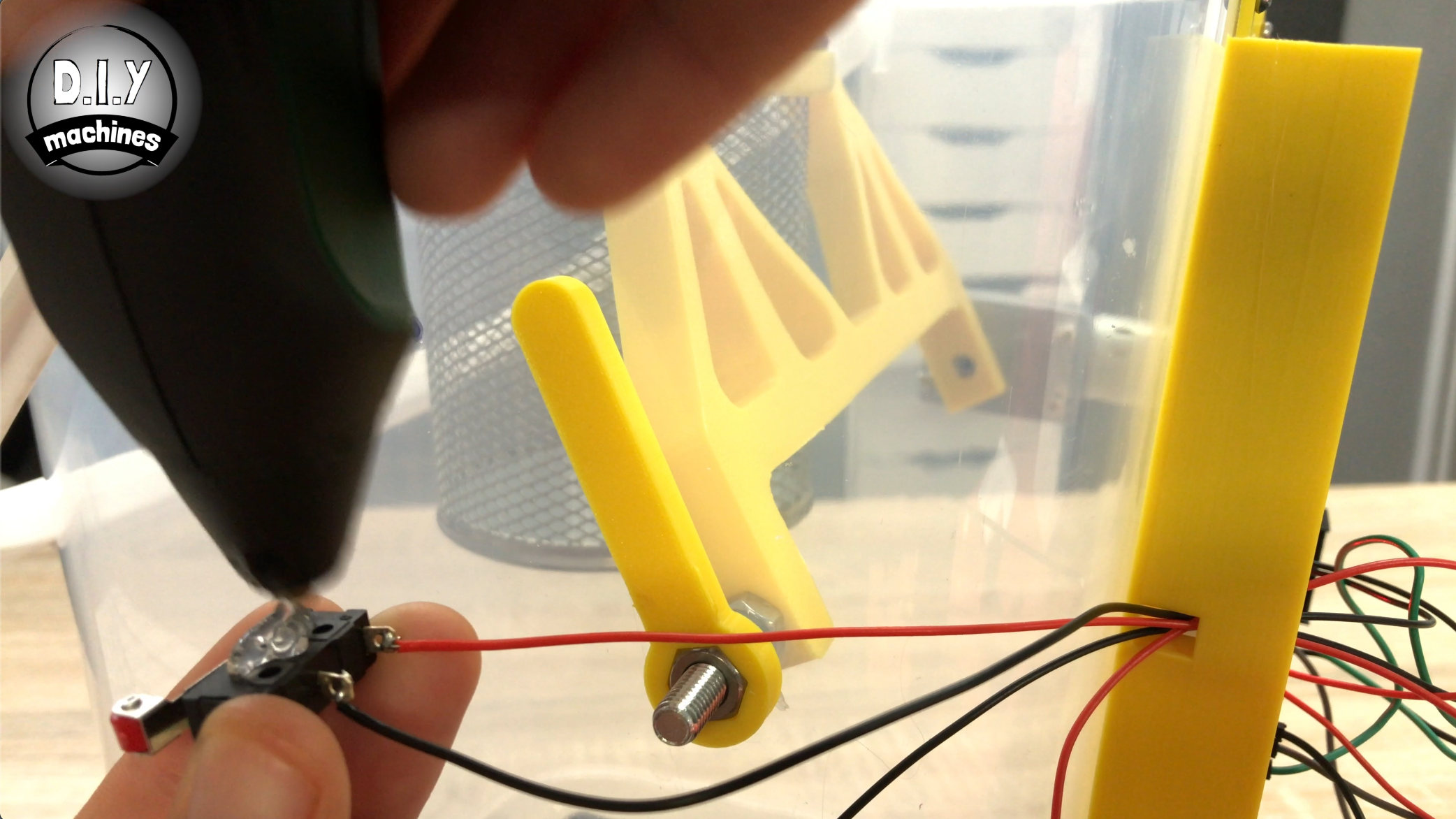
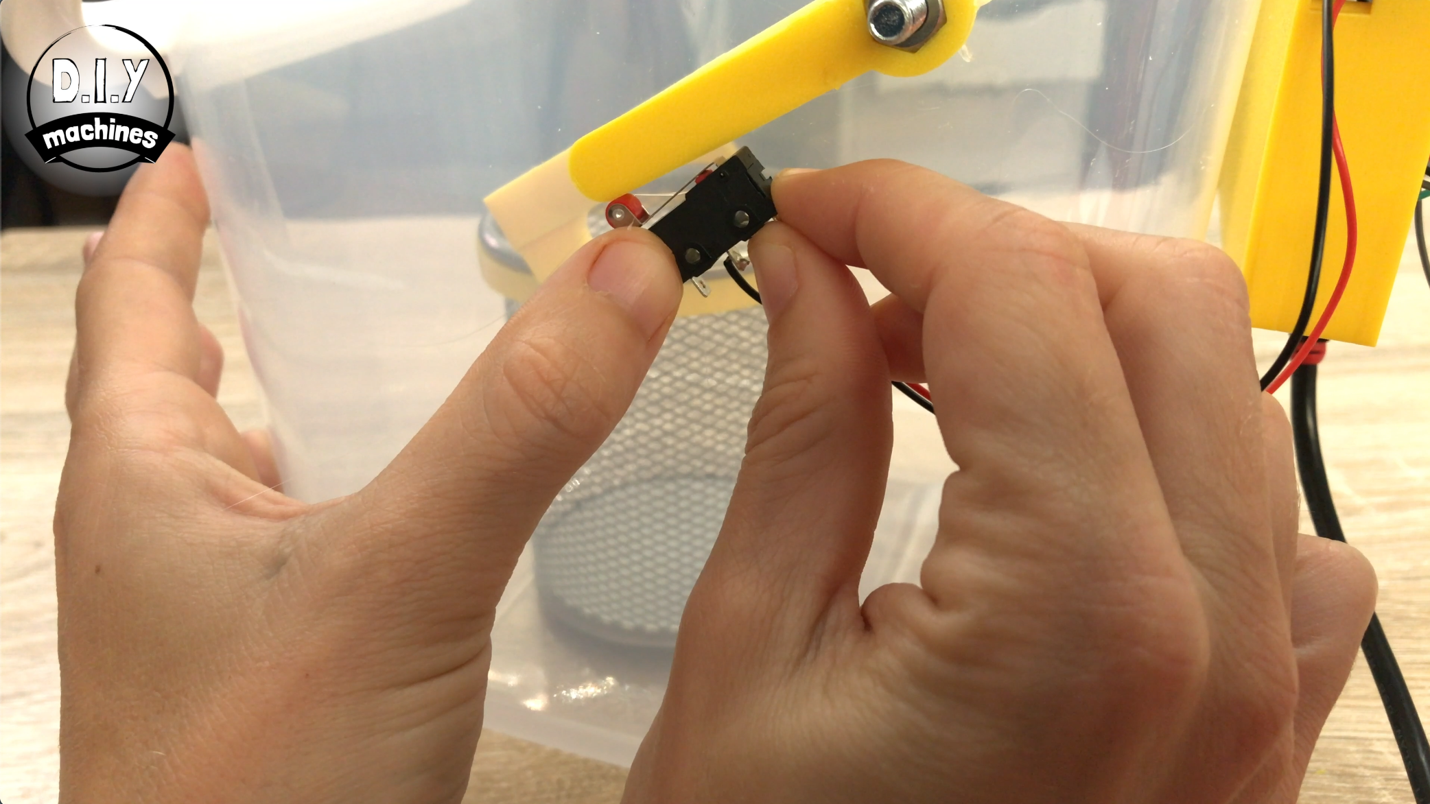
Now apply some glue to the contact switch which is connected to Digital 4 on the Arduino. You want to push this into places that the contact switch is engaged its current position.
You can test that this switch is working by sending a capital 'D' through the serial monitor to lower the container and then sending some capital 'U's for 'up'. The container should stop trying to move once it hits the contact switch.
Now for the lower limit switch, send the capital 'D' for down again until the stationery container is just touching the bottom of the container.
This is the position where you will want to glue the other switch. Remember, the contact switch wants to be already pressed when you glue it up against the leaver. Test this switch again just like you did with the previous one.
Now you might find like me that you have some surplus wire. you can shorten these wires and it will help to tidy up your electronics.
Step 15: Connect Bluetooth Module
For this step prepare:
- HM10 bluetooth module
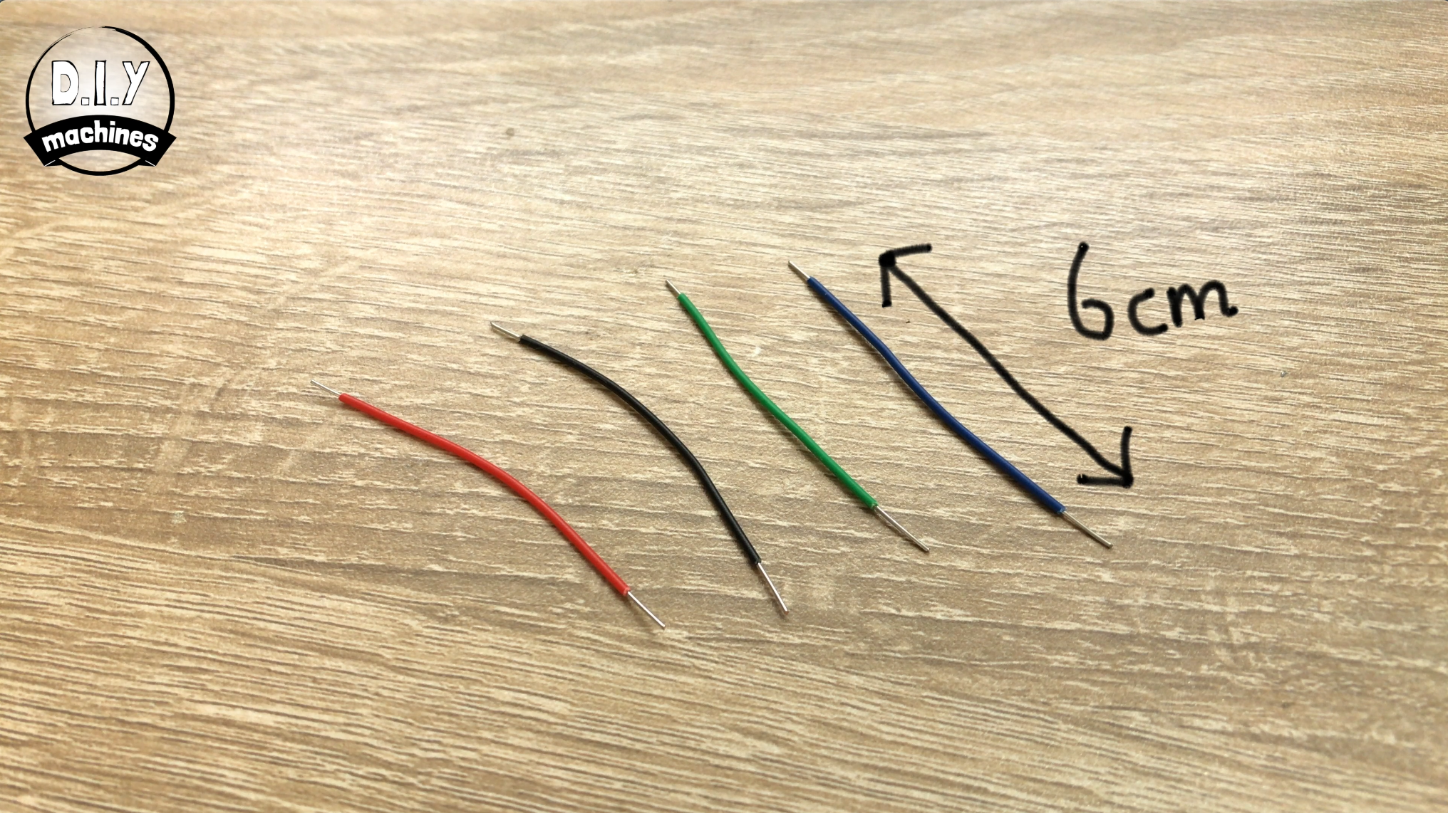
- 6cm lengths of wire (x4)
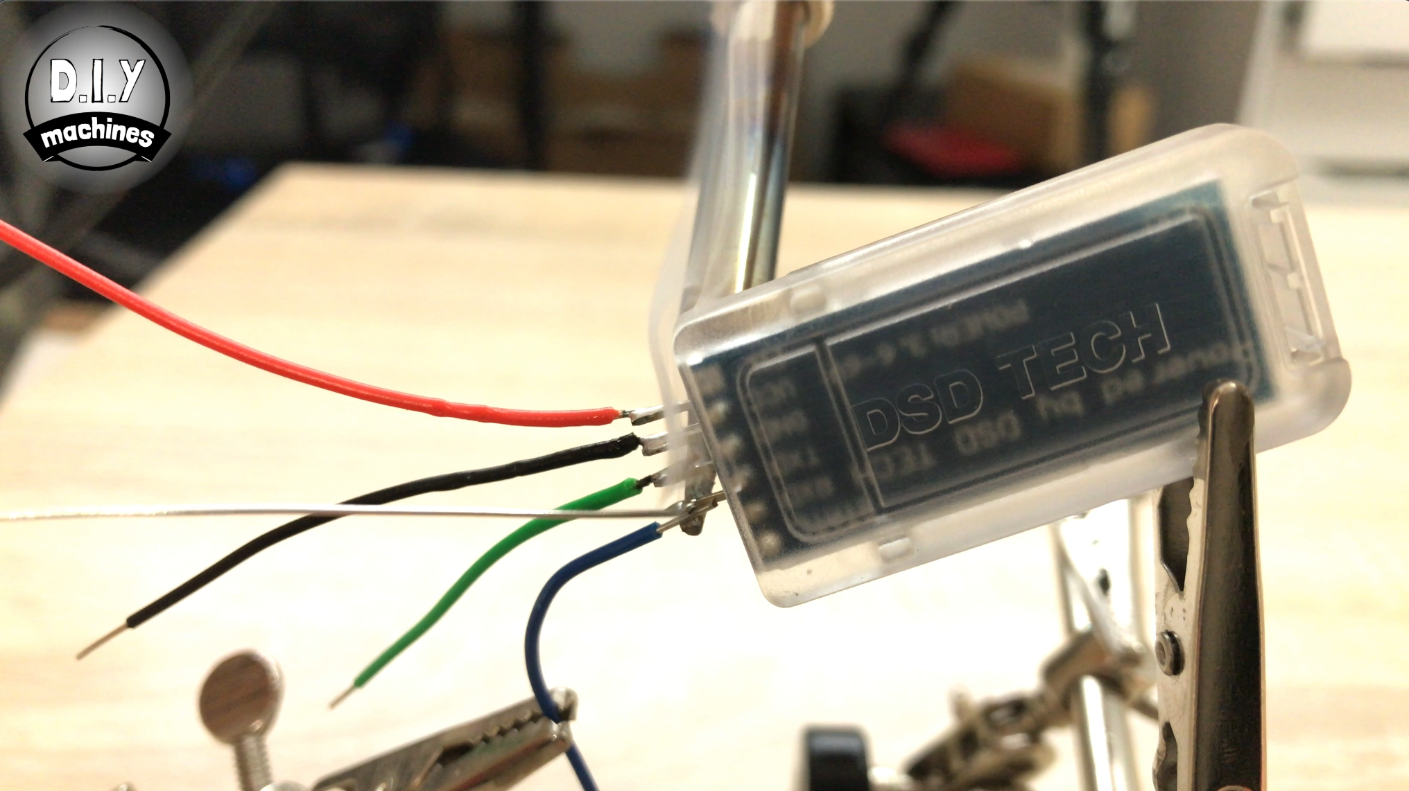
Take the bluetooth module and solder four 6cm lengths of wire to each of the four legs.
- Connect the wire from VCC on the bluetooth module to 3.3v on the Arduino Nano.
- The ground wire can go to a ground connection.
- The wire which is coming from Transmit on the bluetooth module wants to go to the receiving one on the Nano.
- The receiving wire from the HM10 module wants to go to the transmit connection on the Arduino Nano.
Carefully bend the wires on the bluetooth module and install it into its place.
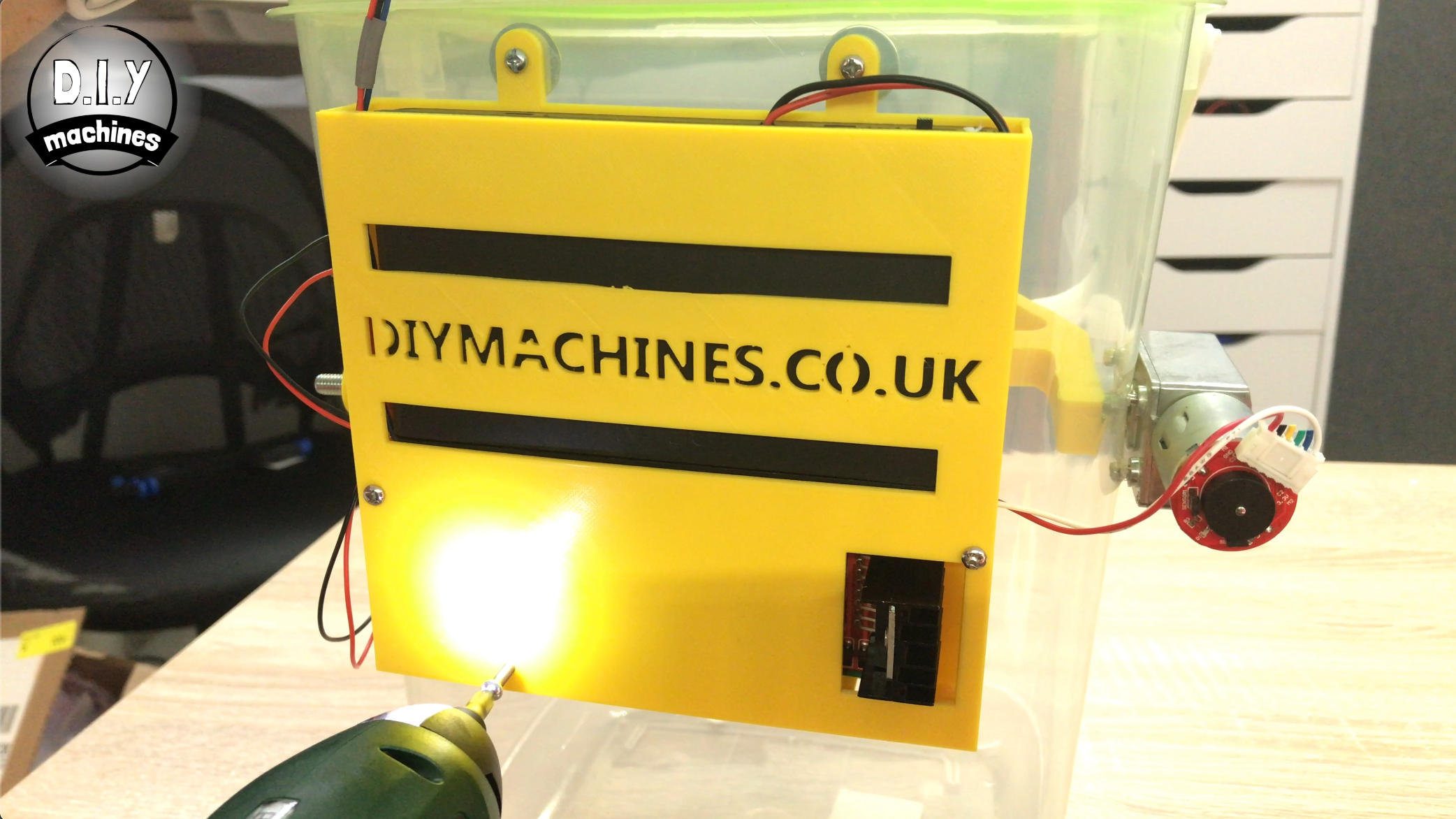
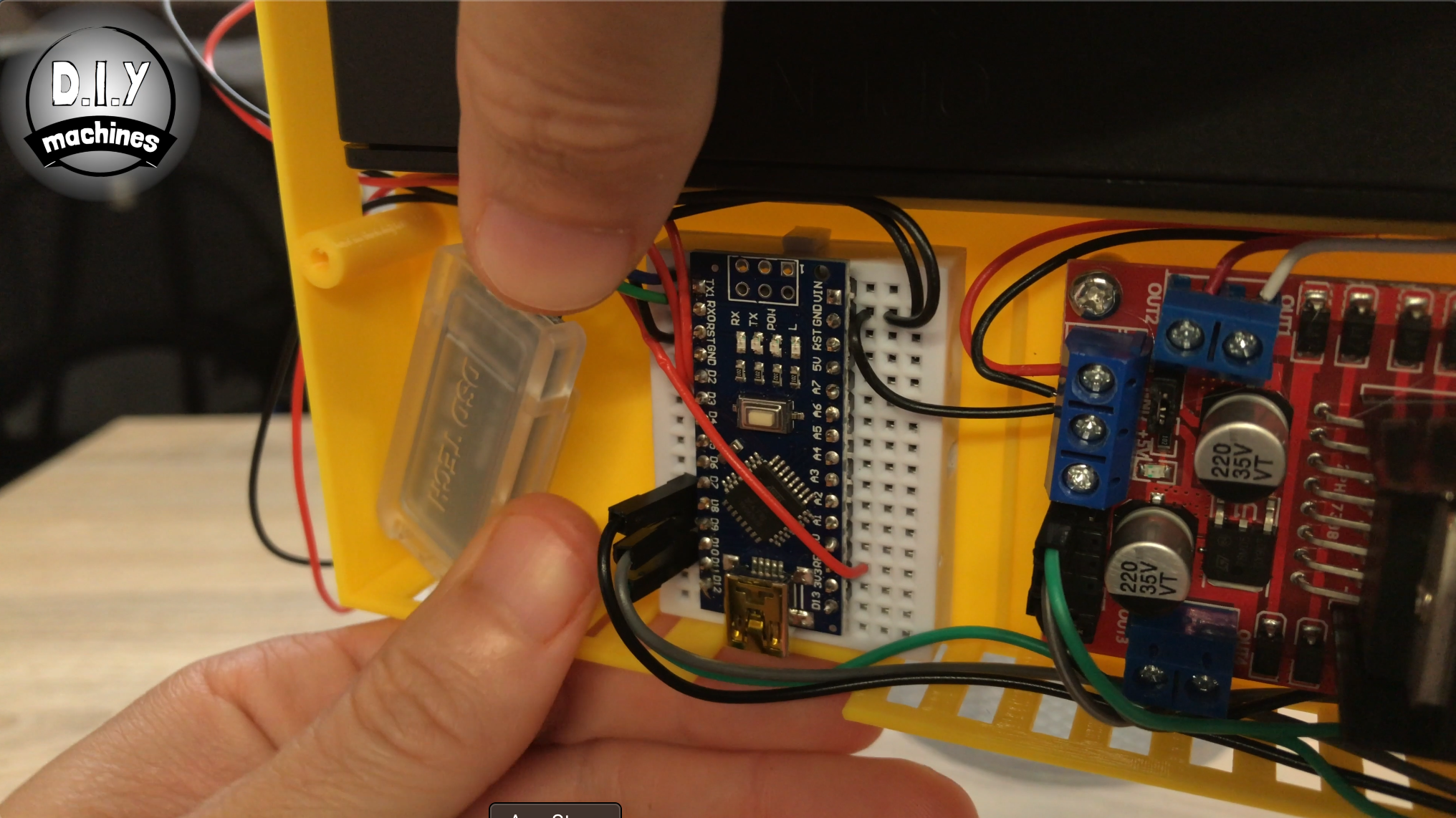
Step 16: Connect the Arduino to Battery Power
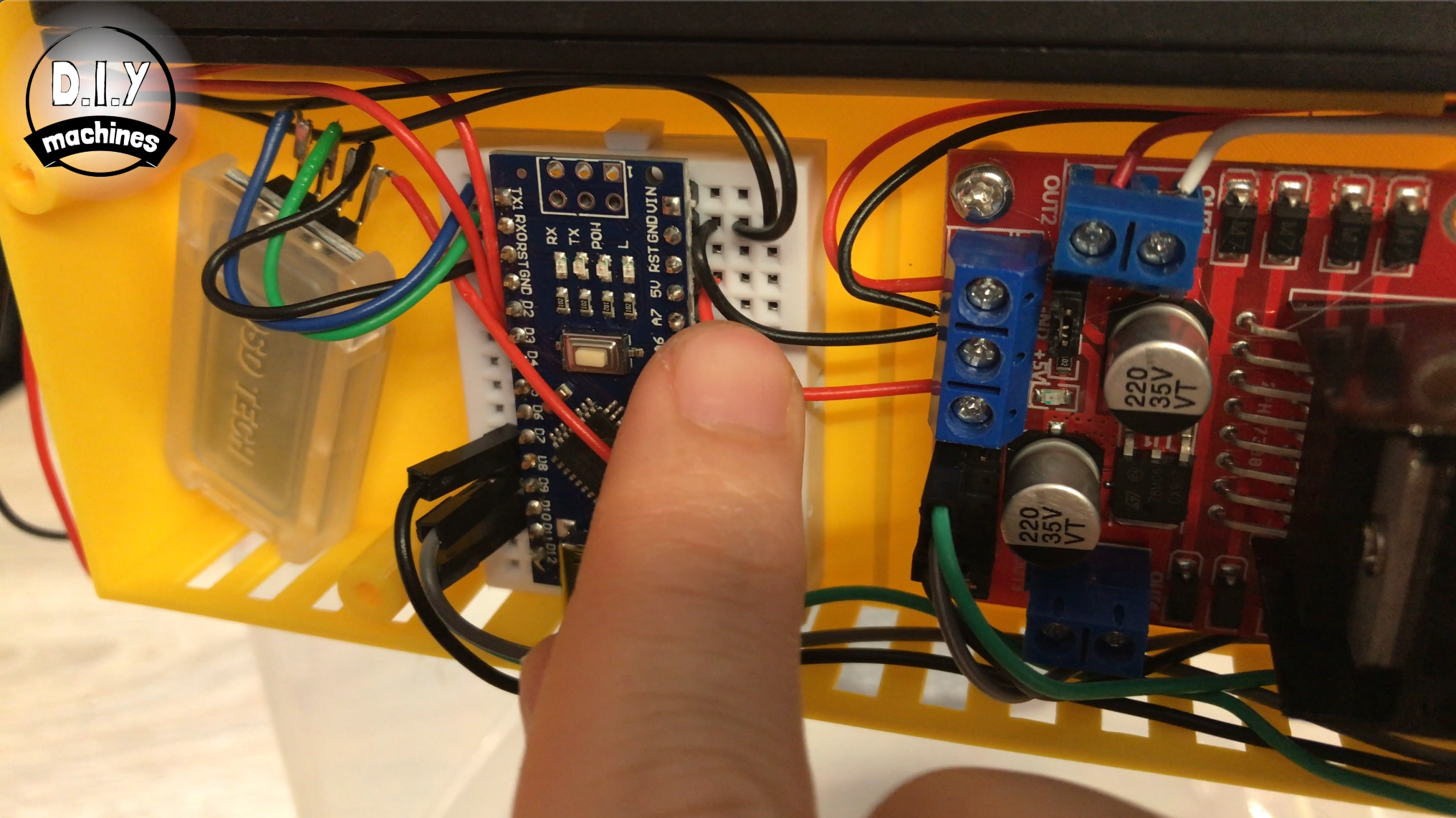
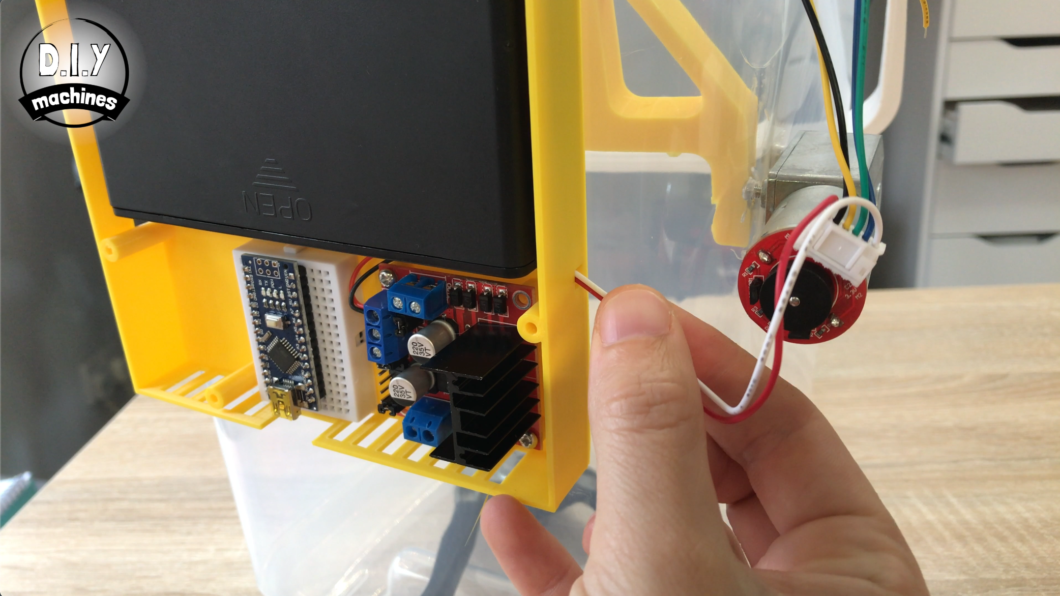
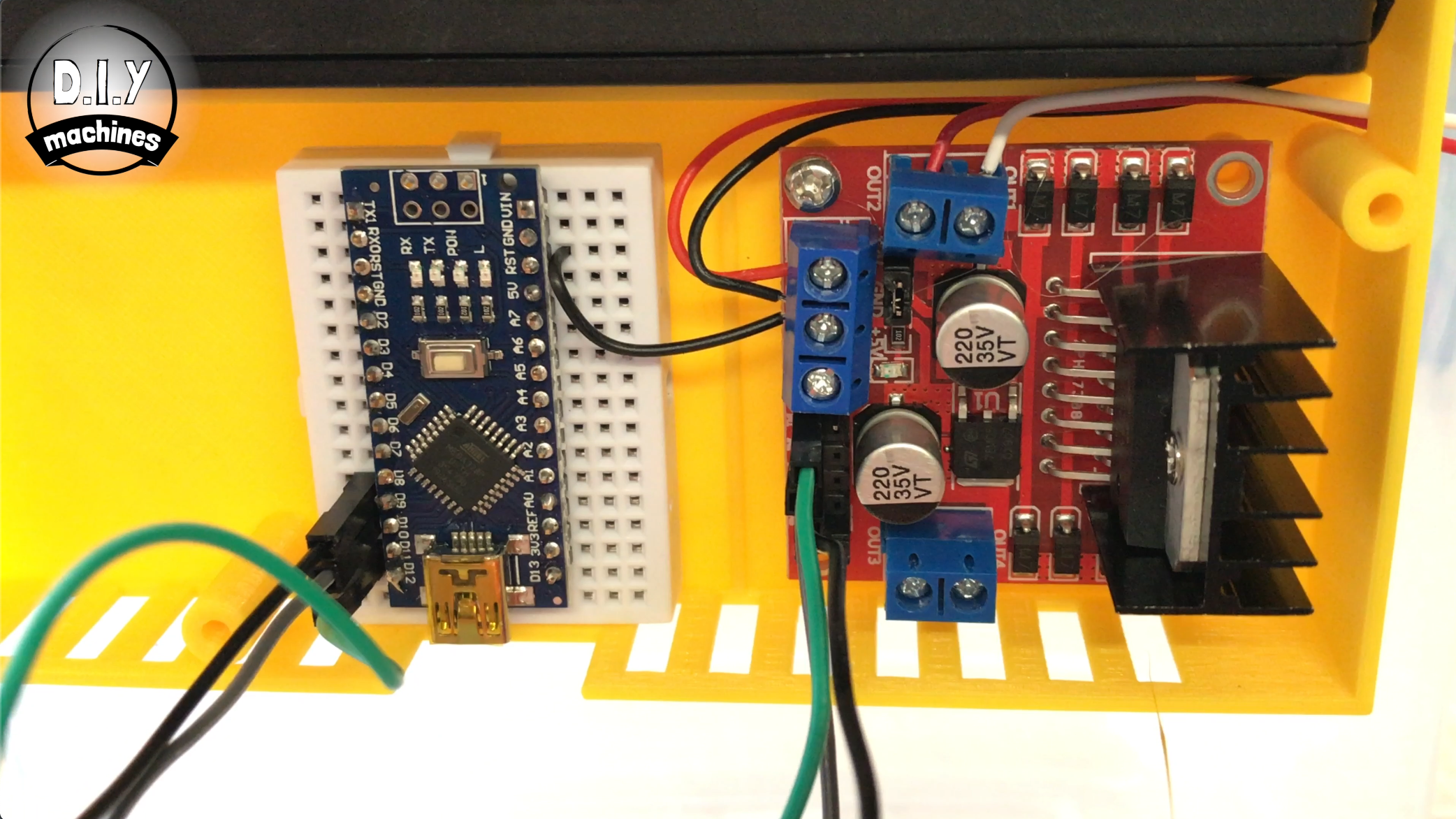
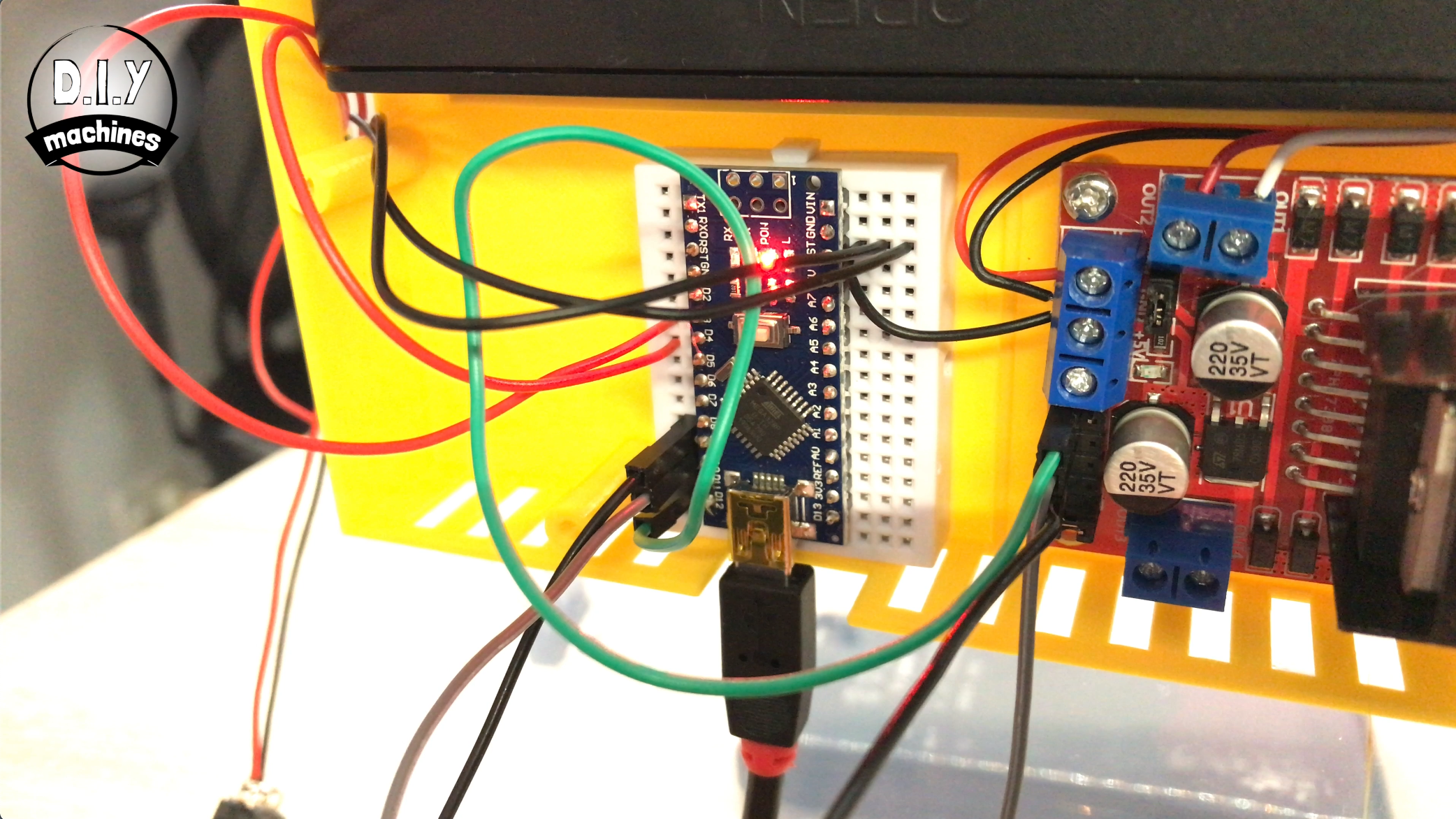
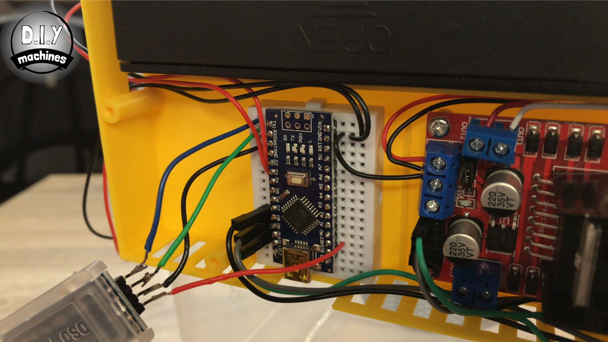
Now we can connect the Arduino to the battery power. We will do this via the 5v output on the motor board as our batteries are providing about 12v if we connected directly to them.
Add a short length of wire between the 5V connection on the motor driver (the bottom of the three terminals together) to the 5V pin on the Arduino. It's the red wire I've got my finger on in the photo.
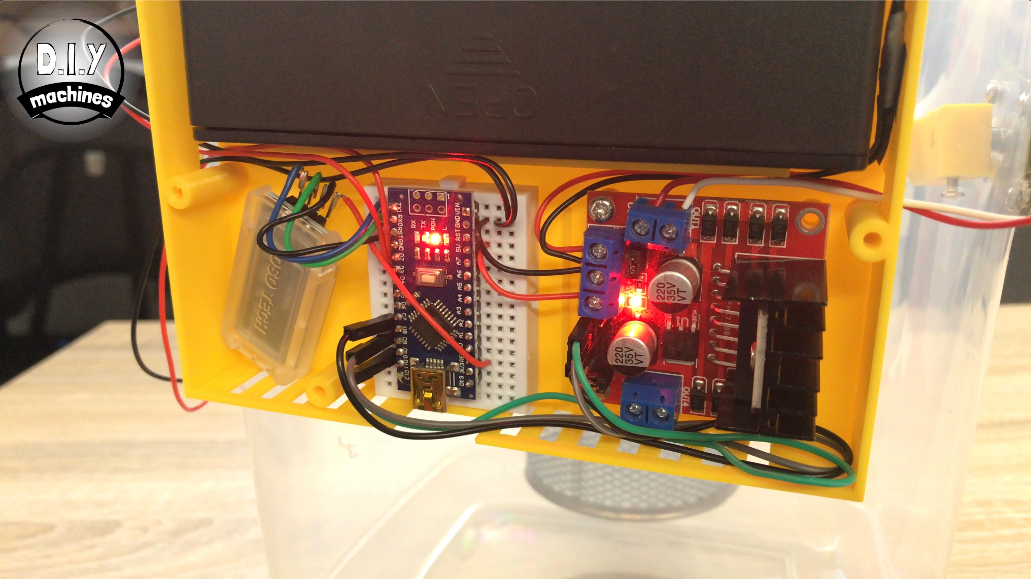
If you have done it correctly, when you turn on the battery pack LED's should light up on the motor driver, nano and bluetooth module. :)
Step 17: Nozzle Assembly Preperation
For this step prepare:
- Lid of the container
- Marker pen
- Scissors
- Either one of the two nozzle options printed
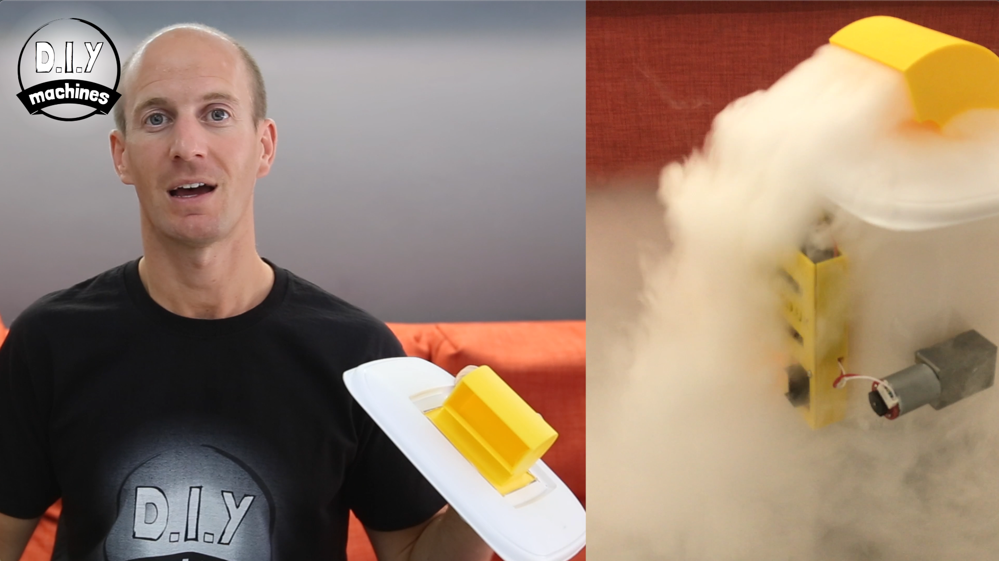
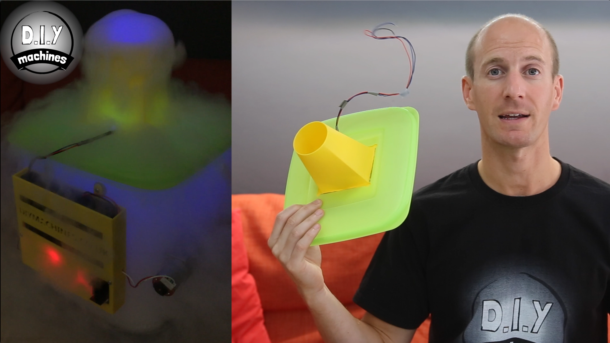
There are two different nozzles which I will show you how to build.
'Nozzle 1' is the one shown in the white lid above. It is brilliant for creating a thick ground hogging fog.
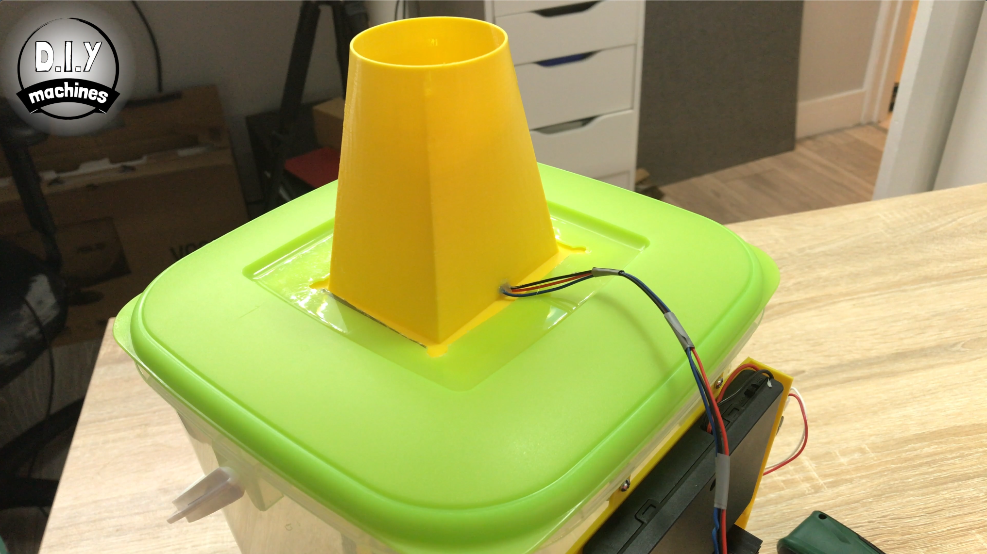
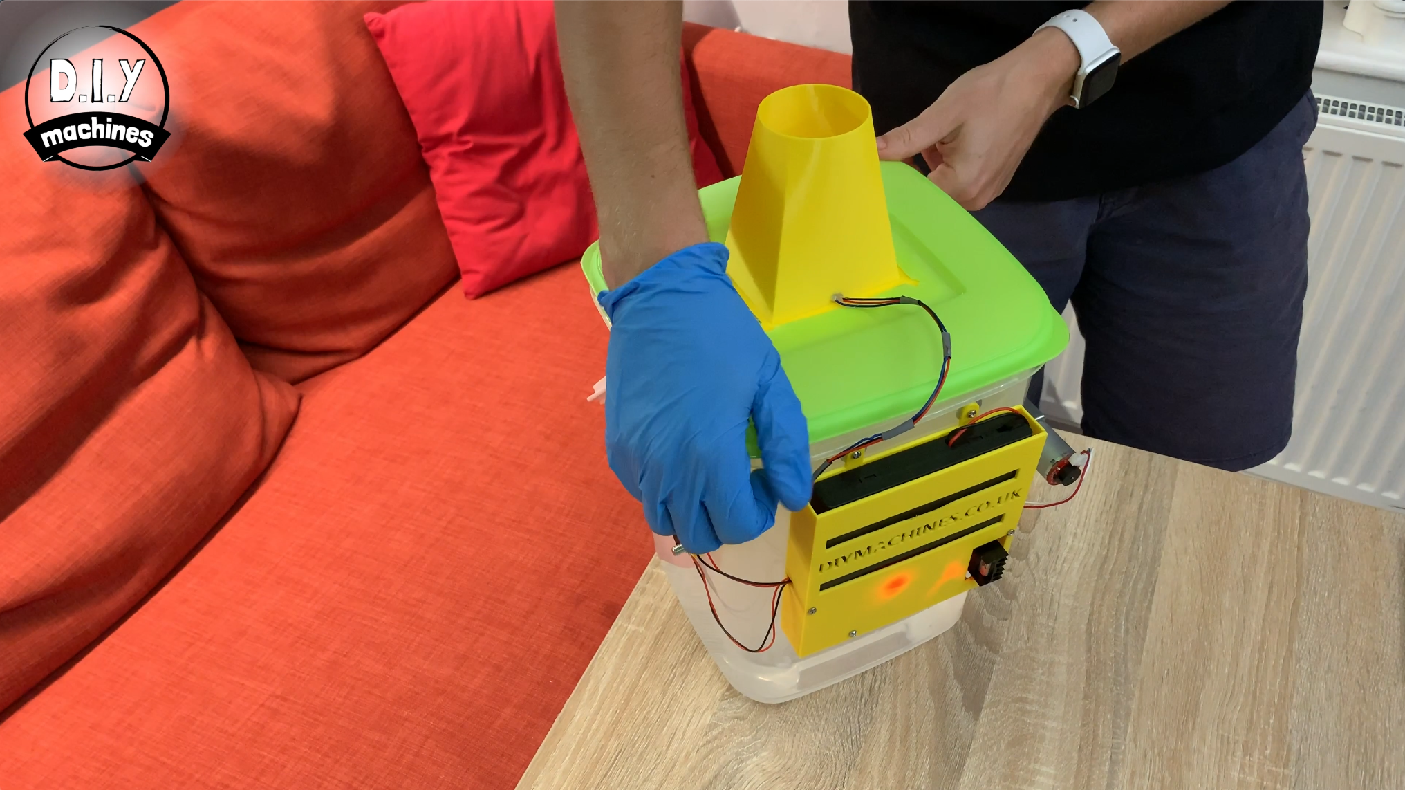
'Nozzle 2' is the one shown in the green lid. This one acts more like a volcano and spews the fog upwards. It also has integrated LED's which allow you to light the fog up.
For both of them we need to prepare the lid in the same way so I will explain that in this step and then if you want to make 'Nozzle 1' then continue onto the next step, and if you want 'Nozzle 2' then skip the next step.
Of course you can always make both and easily swap them over.
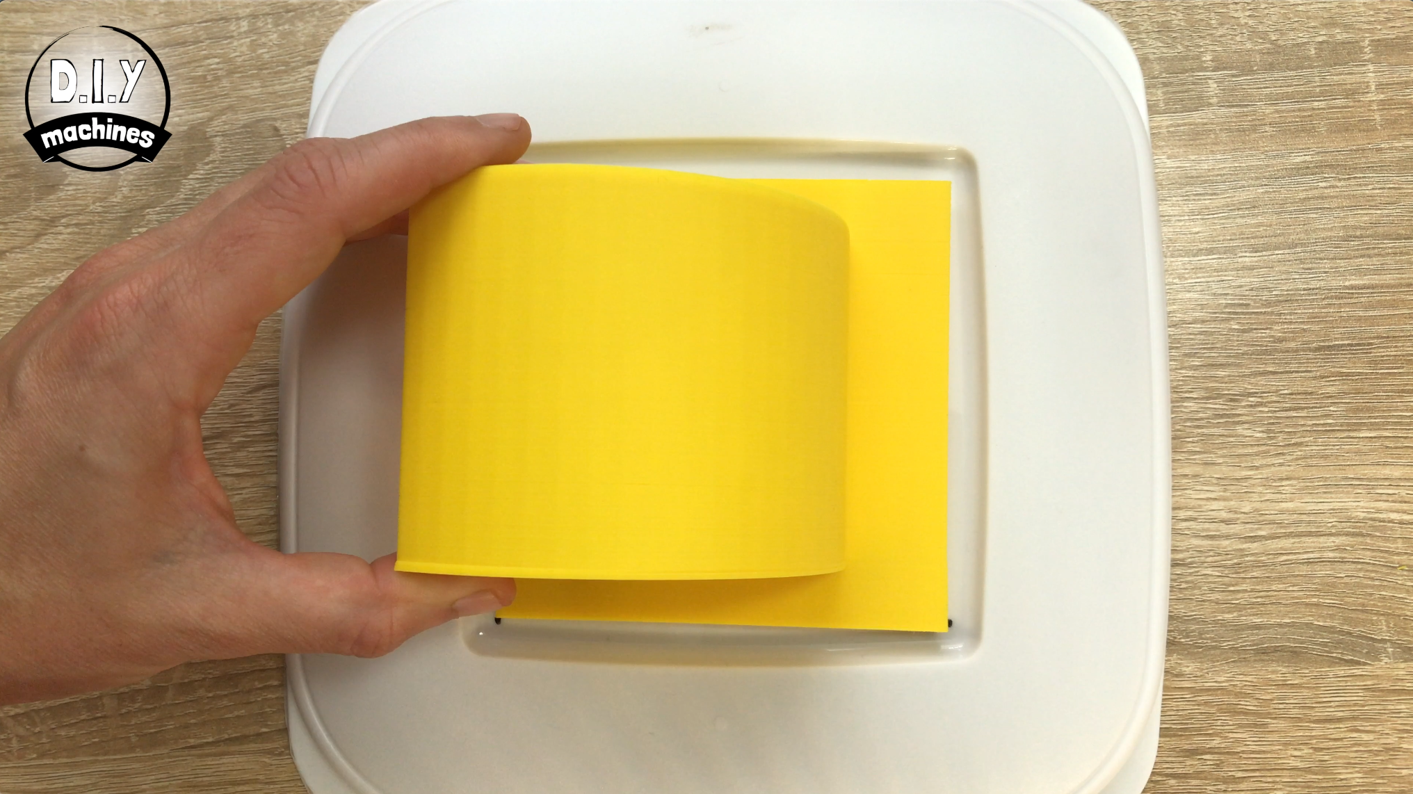
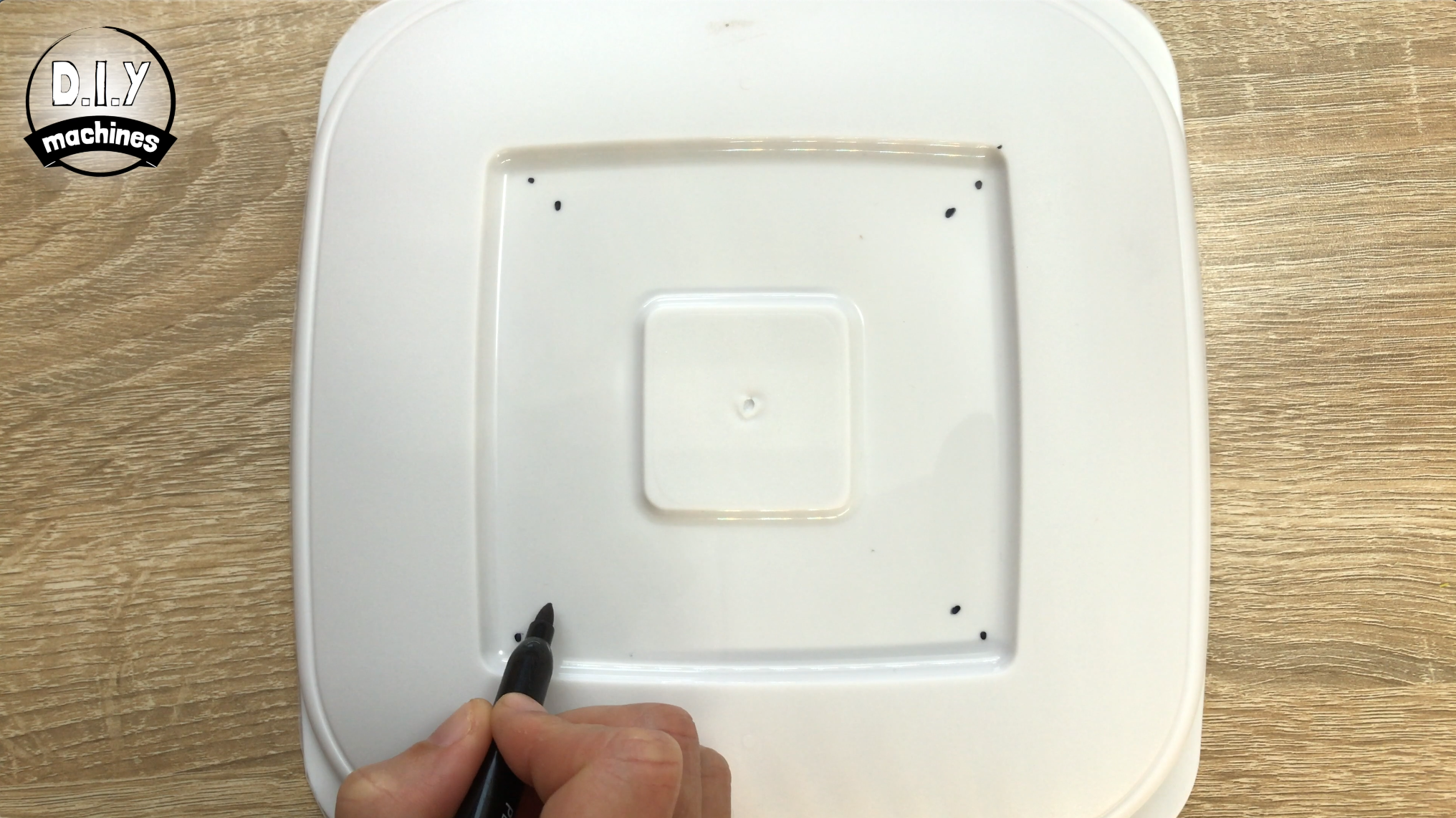
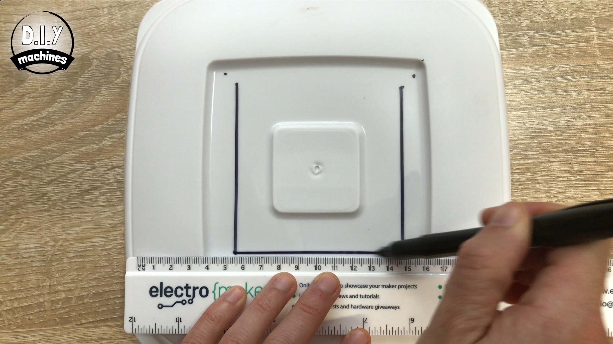
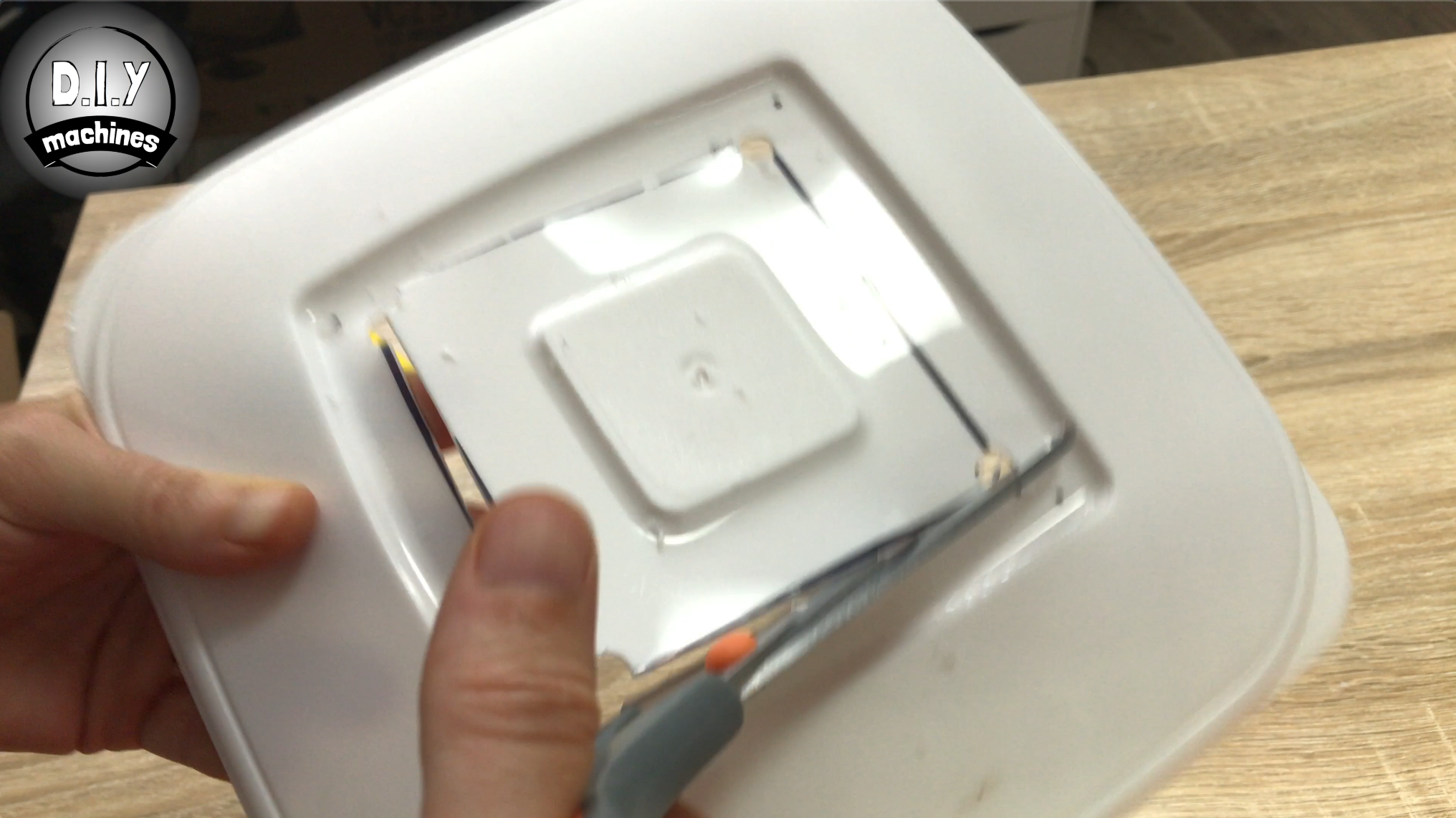
Take either one of the printed nozzles and place it on your lid. Mark where the four corners are. Remove the printed nozzle and make another set of point about 1cm inside of the first four.
Draw lines between these dots and then cut out the resulting square.
Step 18: Fitting 'Nozzle 1' - Low Fogger
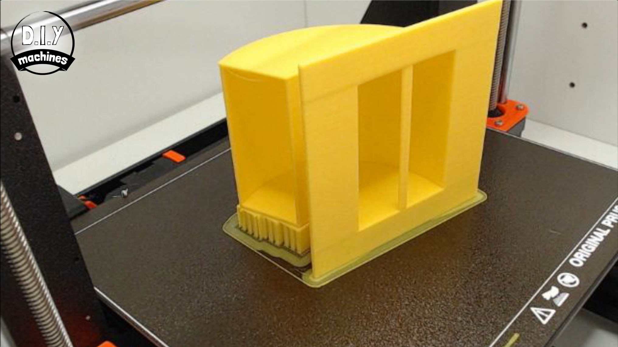
If you haven't already, print the nozzle. I printed mine at a layer height of 0.2mm, on its side with support on the build plate only. I also added a brim to help the print the adhere to the print bed.
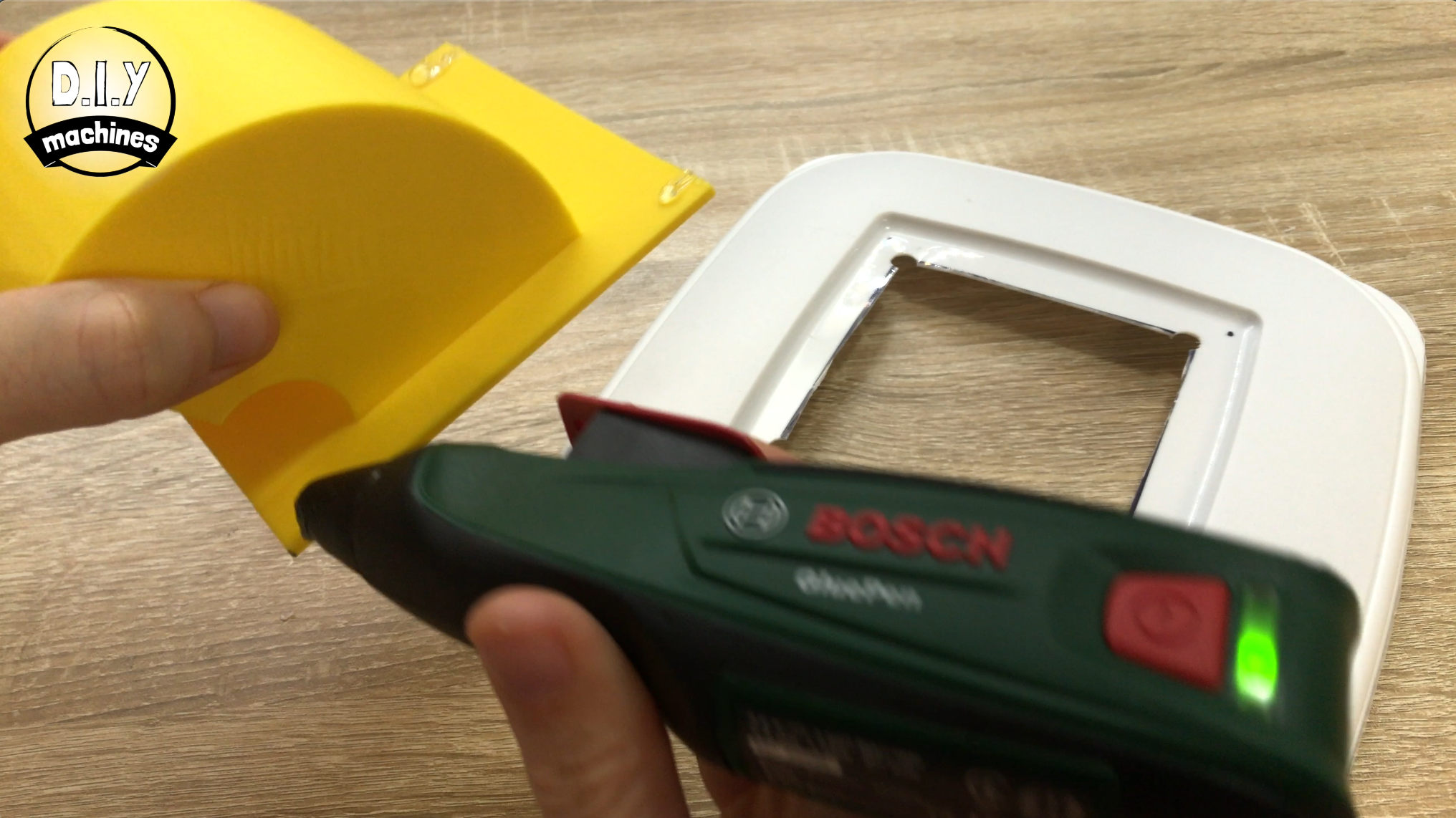
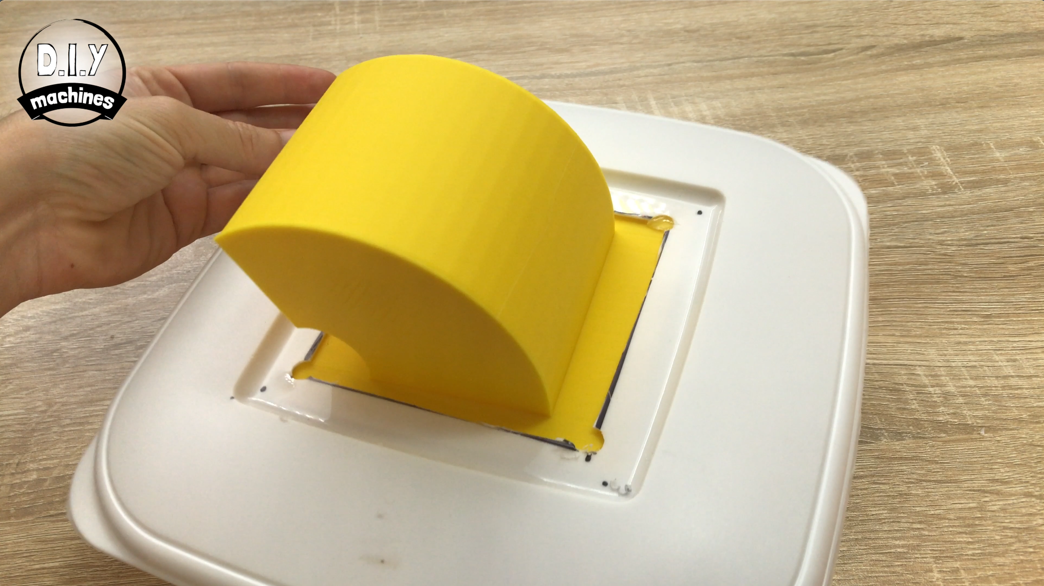
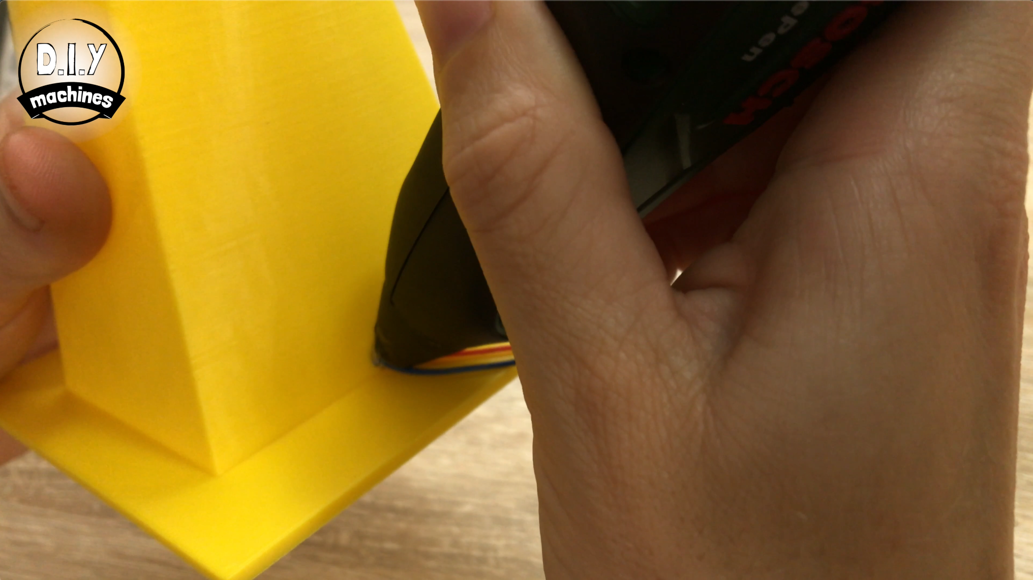
Remove the supports and then add some hot melt glue around the edges of the top side. This can then be passed through the hole in the lid from the underside.
That's it for this nozzle. I said it was super simple. :)
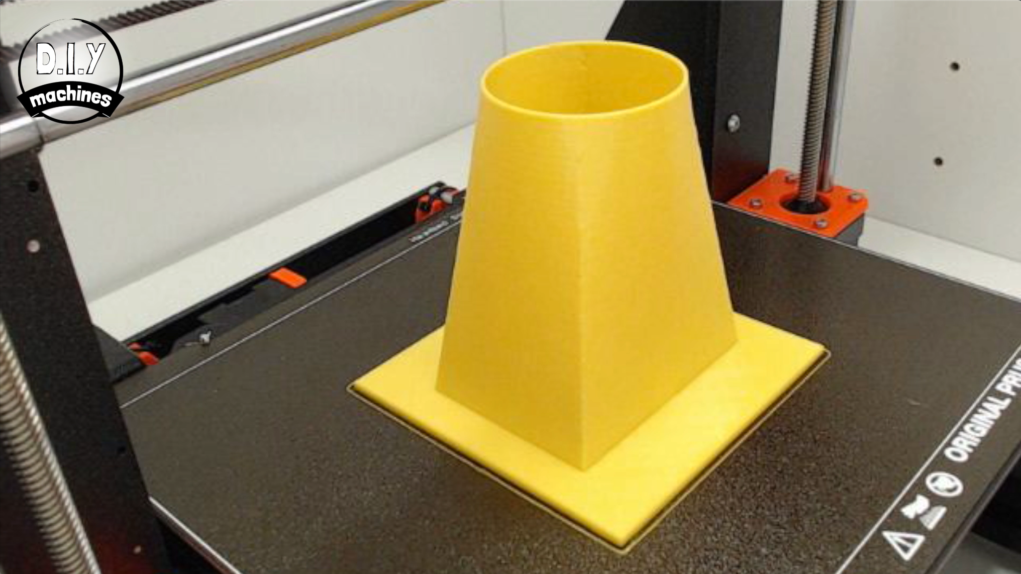
Step 19: Fitting 'Nozzle 2' - Volcanic Fogger With LEDs
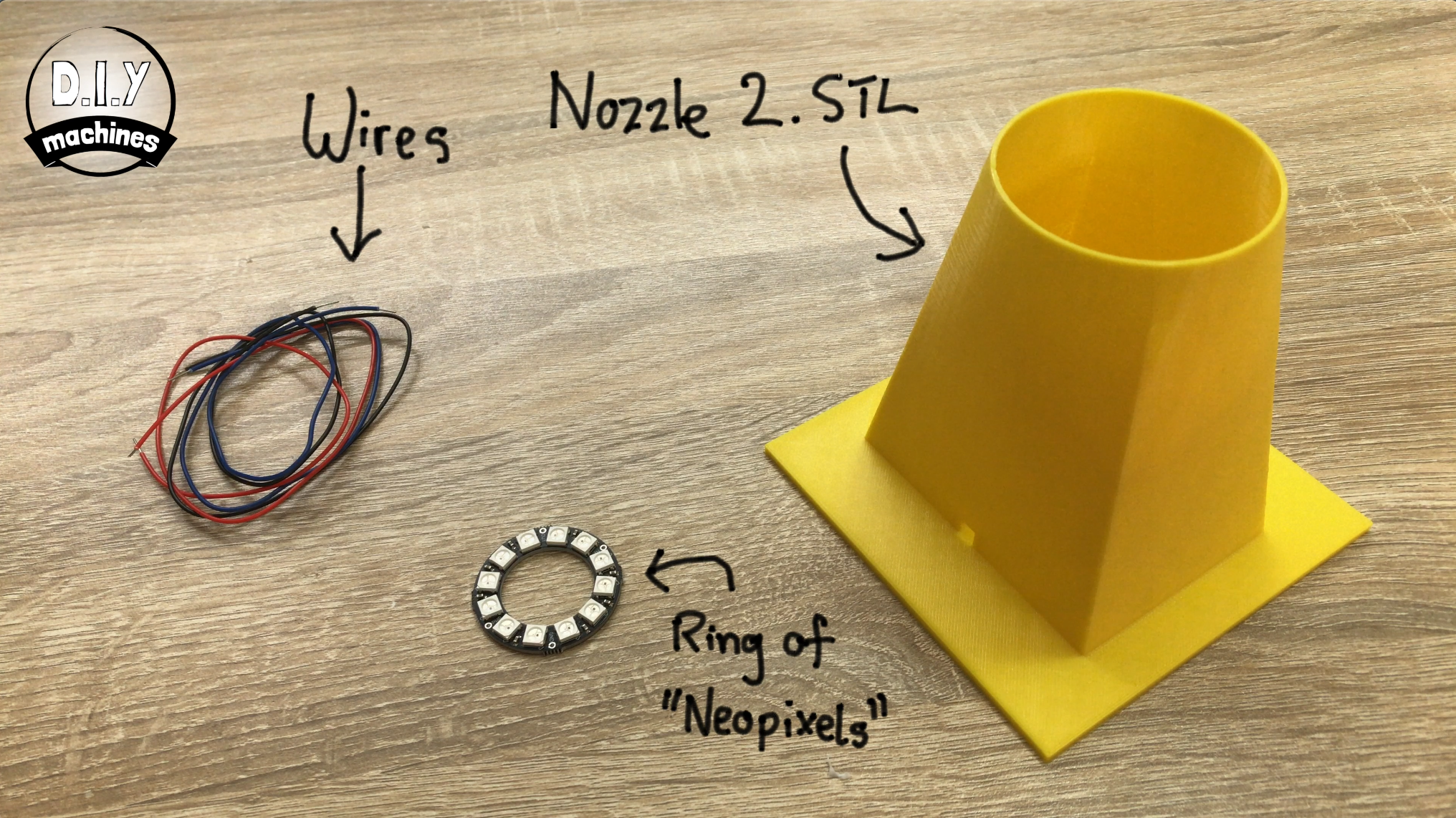
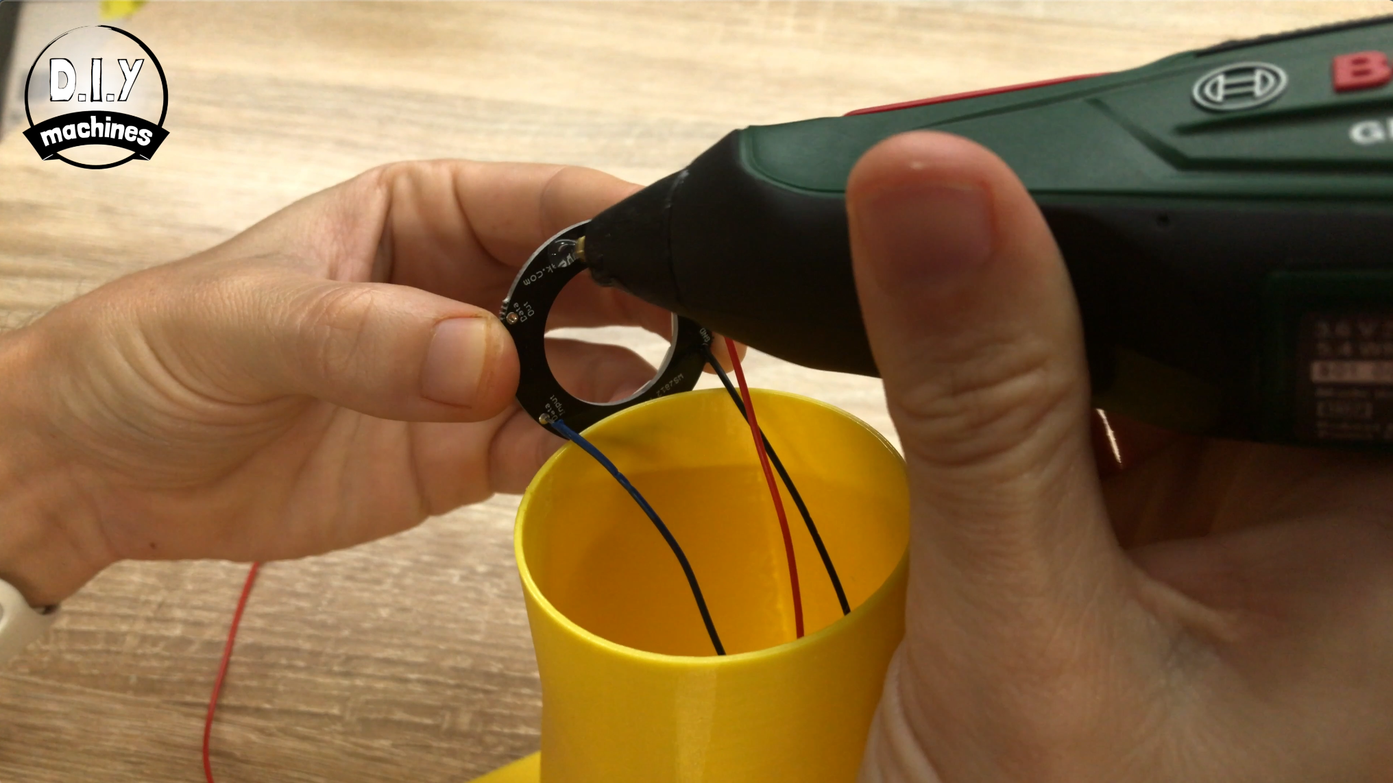
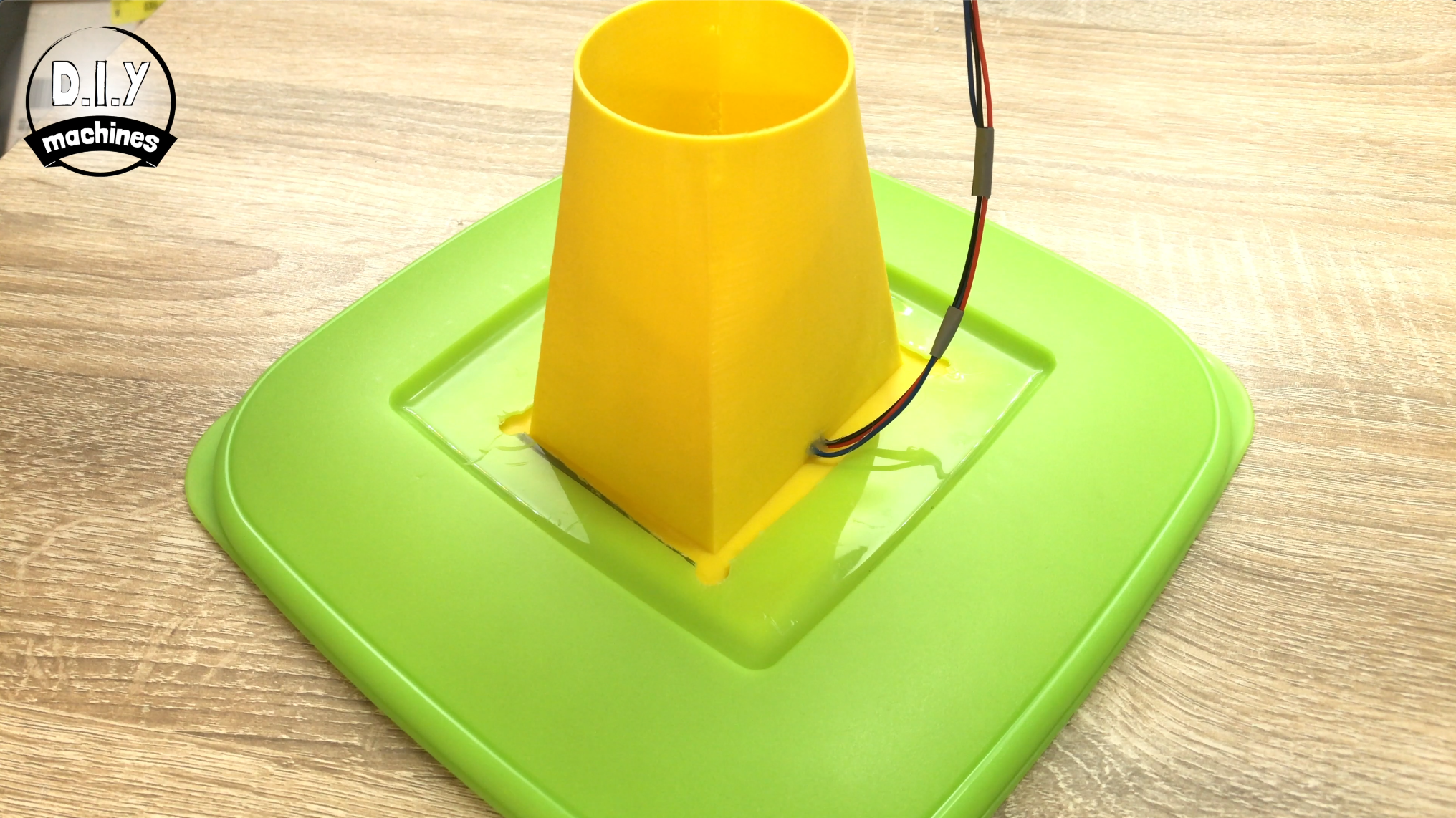
For this step you'll need:
- Wires
- Ring of 'Neopixels'
- The 3D printed nozzle
If you haven't already then print the part for this nozzle. This time I printed it upright without the need for any support or brim.
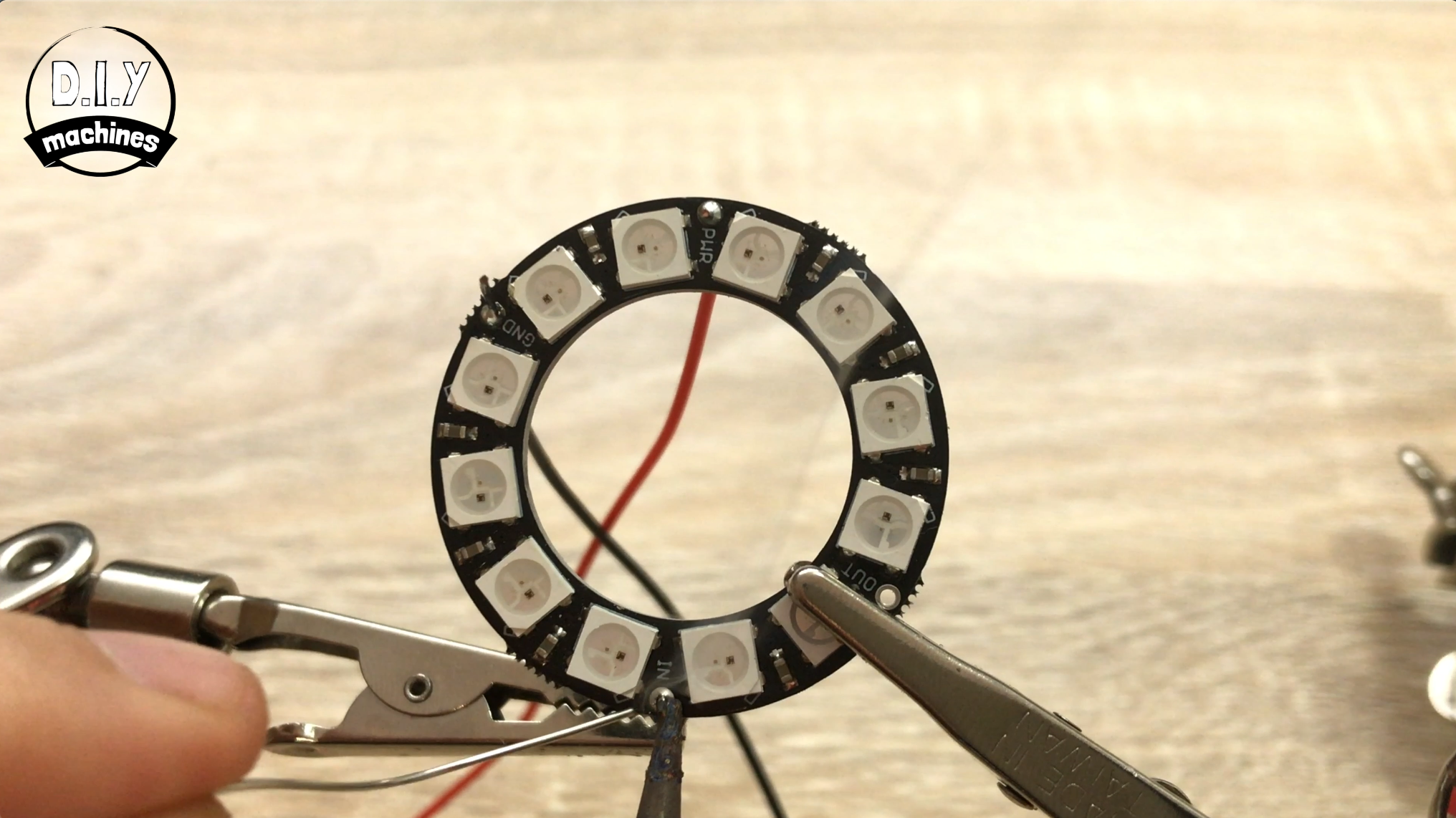
Solder a long length of wire (I made mine 40cm long and then trimmed it shorter later on when I new exactly how much was needed to reach the Arduino Nano) to each of the following pins:
- PWR (Power - might also be called VCC)
- GND (Ground)
- IN (Digital in - might also be referred to as DIN)
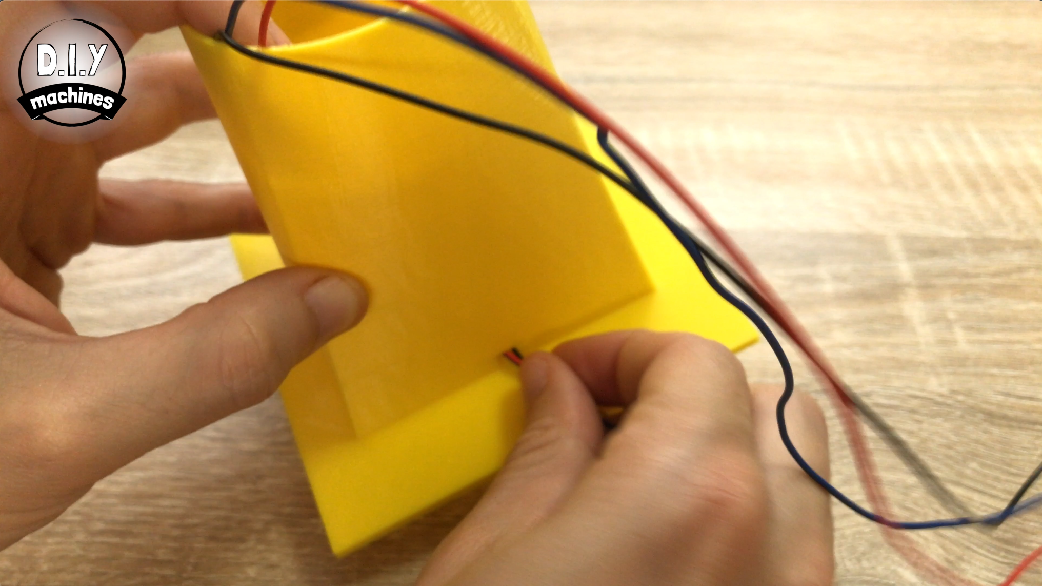
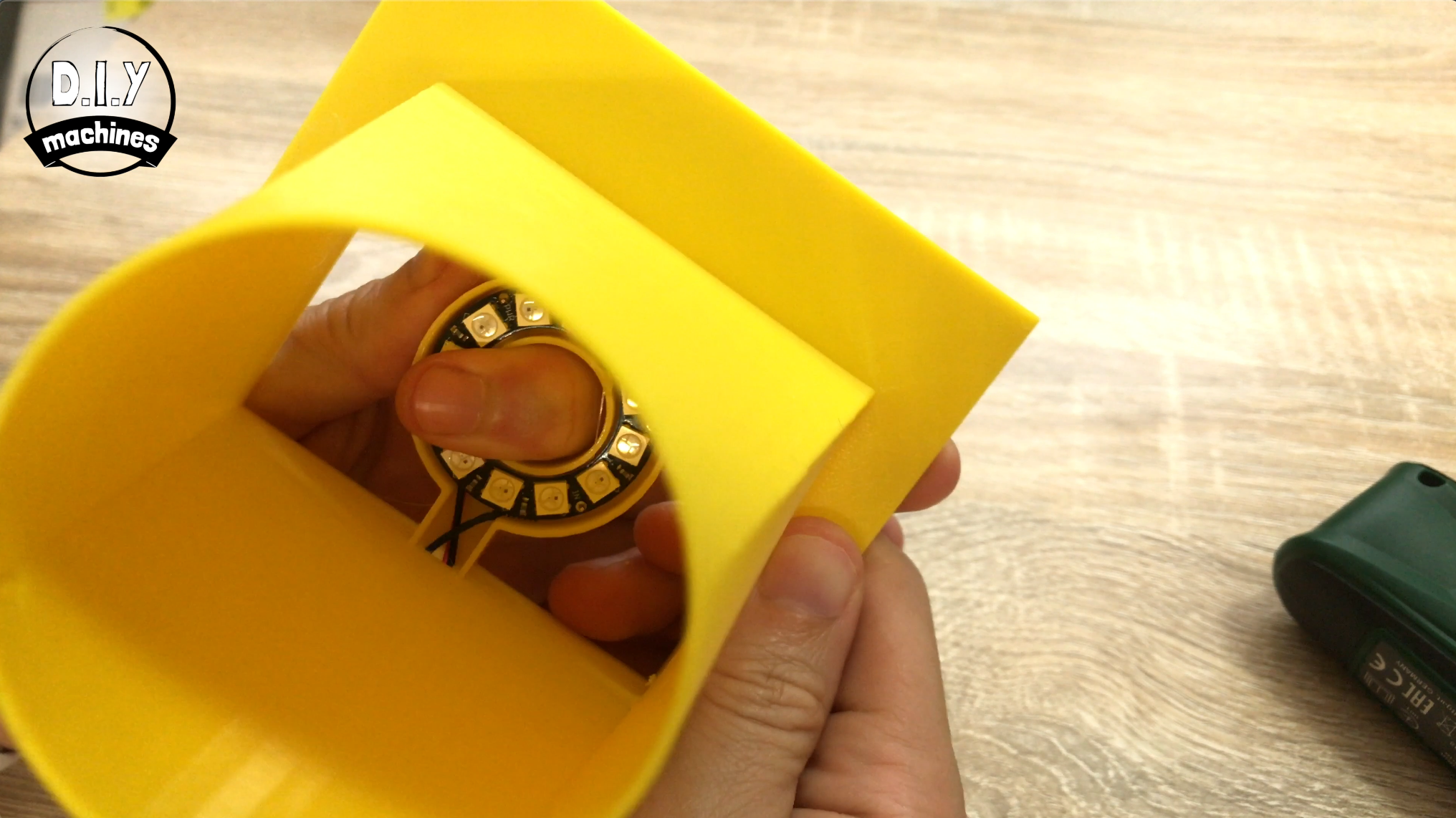
All three wires can the be passed down through the top of the nozzle then back out through the little holes at the bottom of the print. Add some hot melt glue or similar to the back of the LEDs and then push them firmly into their holding spot as shown above.
Once this is done, add another 'blob' of glue to where the wire pass from inside the print to outside the print. This is just to prevent the fog spewing out of this hole. You can also use some pieces of insulation tape to bundle the wires together to help keep everything tidy.
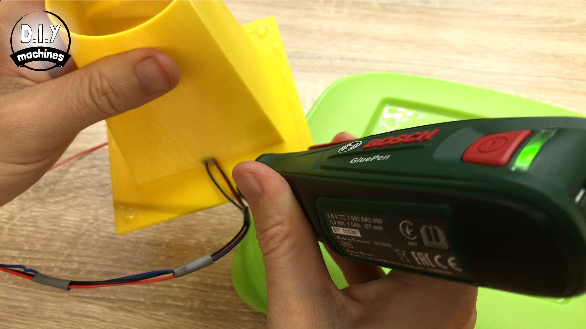
As before, add some hot melt glue around the top side of the print as pass it through the hole in the lid from the underside. Ensure that the wires for the LEDs are also on the top side of the lid.
Clip the lid onto the top of your container and pass the wires down the left hand side of your battery holder. The wire coming from digital innn on your LEDs wants to be connected to pin D6 on the Arduino, VCC is to be connected to 5V and GND to a ground pin.
Step 20: Put a Lid on It
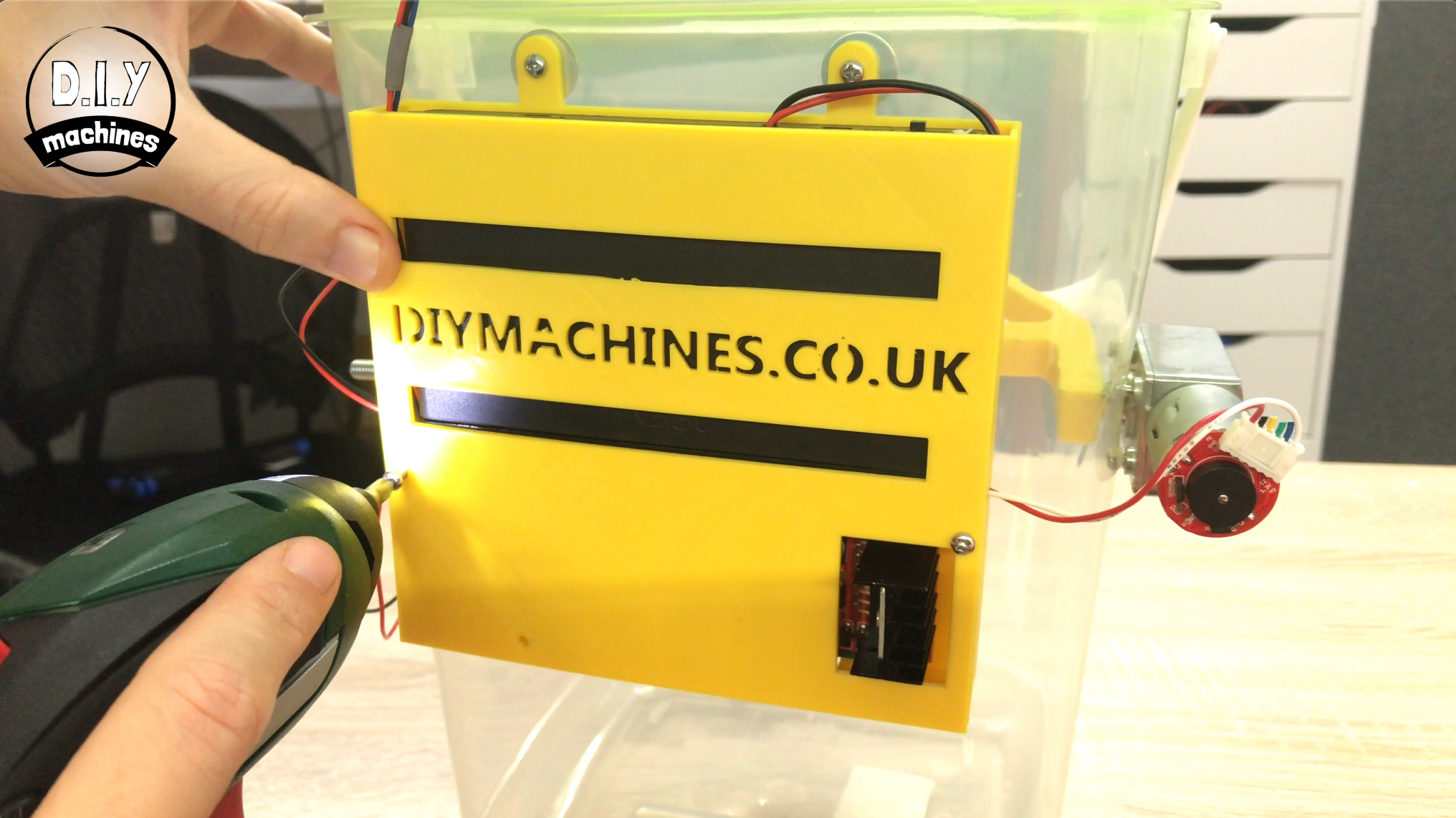
For this step prepare:
- 3D printed lid
- M3 x 6 bolts (x3)
I printed my lid at 0.2mm layer height, no supports and no brim are required.
Now we can fit the lid to the electronics housing.
Use three of your M3 x 6 bolts to secure the lid into place.
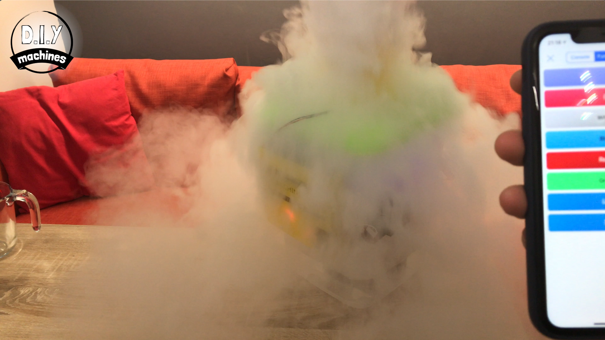
Step 21: Connect Your Phone Via Bluetooth
Now to connect to your dry ice machine via bluetooth you need to download an app to your phone. I'm using an Apple device and have downloaded an app called 'HM10 Bluetooth Serial'. If you haven't already got an app just search your app store for 'HM10 Bluetooth' and you should be able to find something to send serial commands other bluetooth to your Arduino.
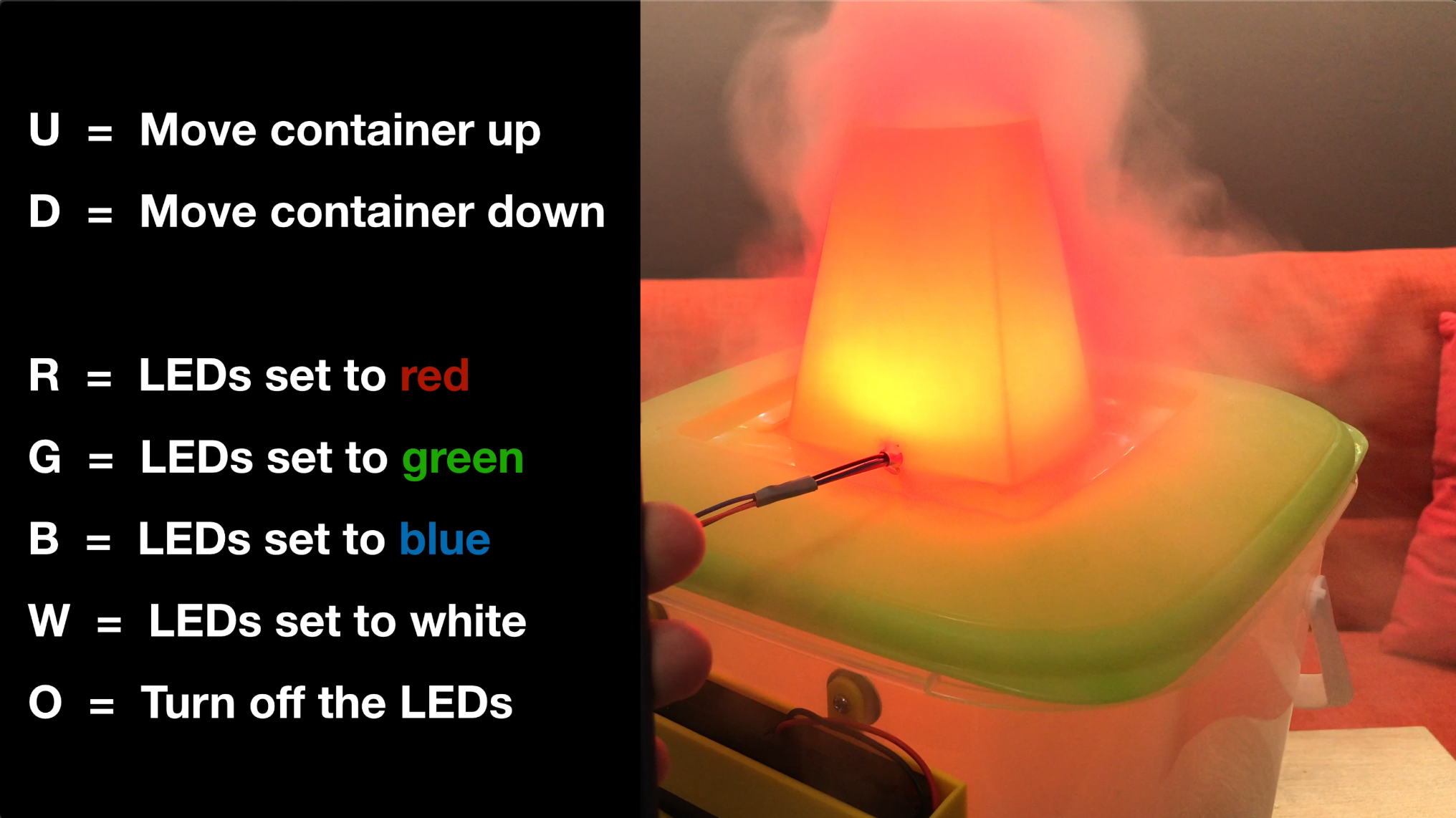
You just need to be able to send a single uppercase character for each of the commands.
- Send a 'U' to move the container upwards
- Send a 'D' to move the container downwards.
Then to control the LEDs you can send
- 'R' for red
- 'B' for blue
- 'G' for green
- 'W' for white
- 'O' to turn off the LEDs.
Step 22: Add the Dry Ice and Party!
For this step prepare:
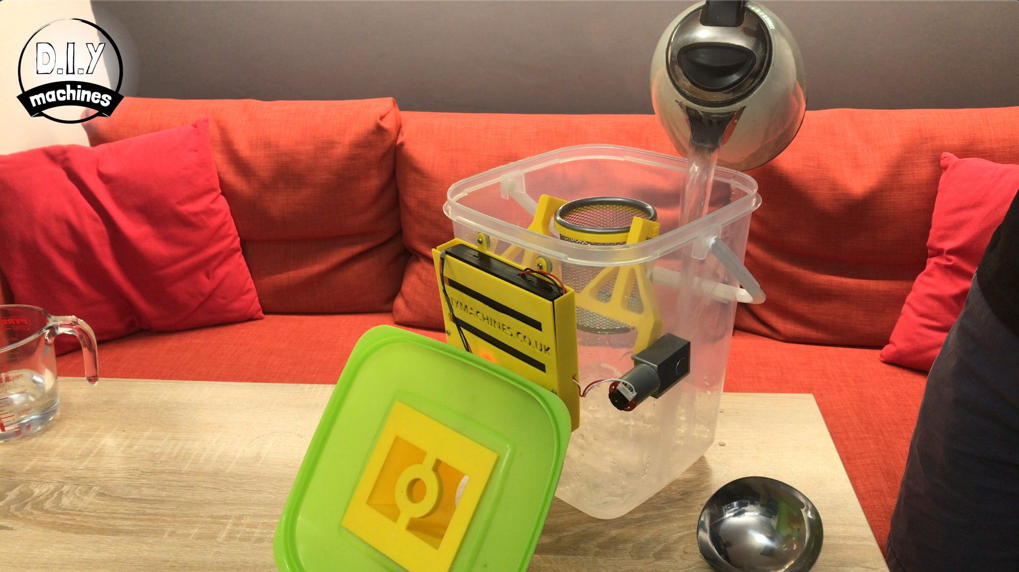
- Hot water
- Dry ice
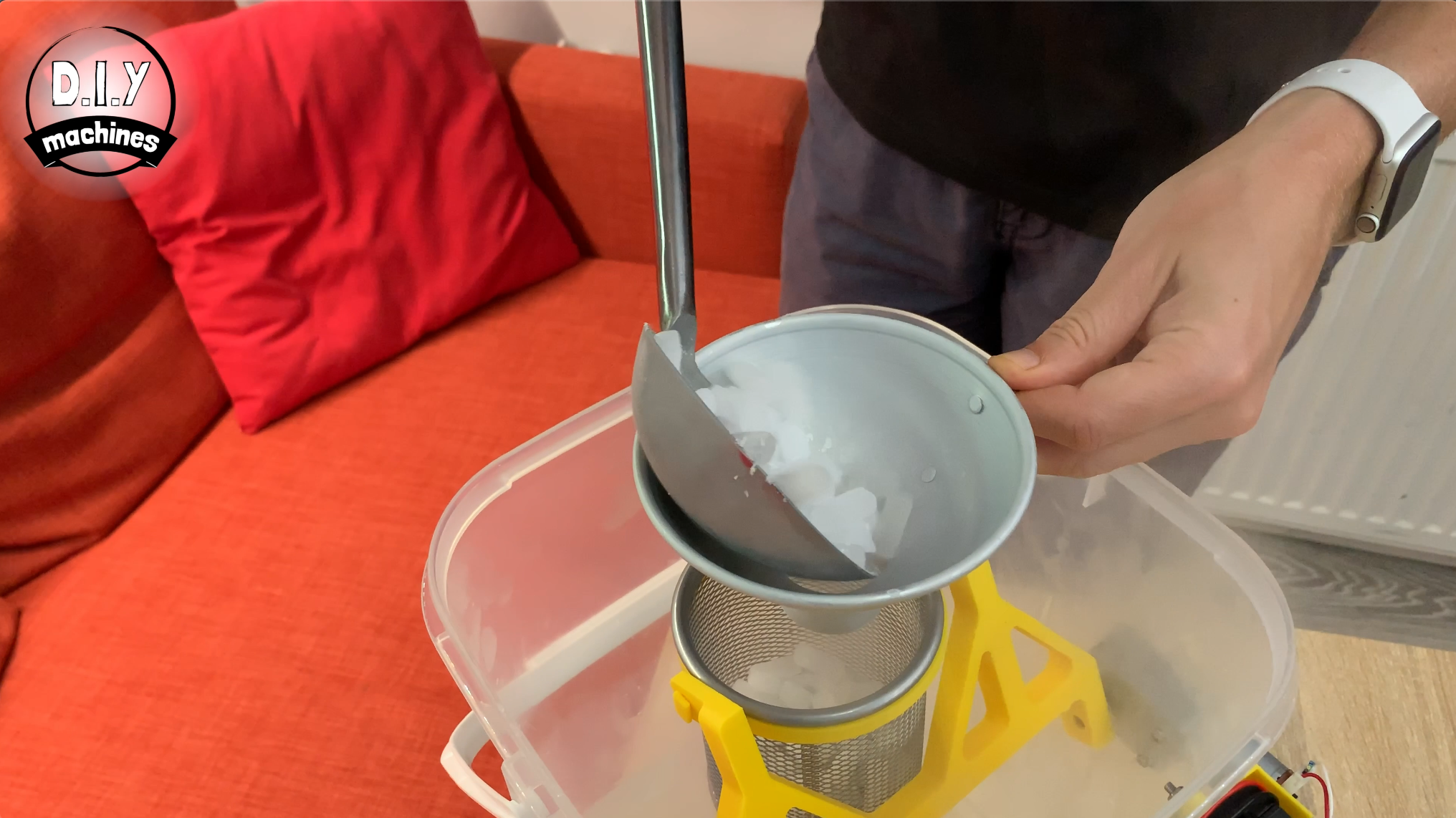
Add plenty of hot (but not boiling water) to the bottom of your container. Next carefully fill the stationary container with dry ice.
Add the lid with your nozzle of choice on it and then connect to your new dry ice machine on your phone via bluetooth.
Once connected you can send single uppercase characters to control it. Here is a reminder of the characters:
Send a 'U' to move the container upwards Send a 'D' to move the container downwards.
Then to control the LEDs you can send 'R' for red, 'B' for blue, 'G' for green, 'W' for white or an 'O' to turn off the LEDs.
Enjoy yourself and take care whilst handling the dry ice. :)
Thanks for taking a look at my tutorial. I hope you've enjoyed this project. If you have please think about checking out some of my other projects, don't forget to subscribe to DIY machines on here and YouTube and share this project with anyone you know who might like to build one of their own.
Otherwise until next time chow for now!
Subscribe to my Youtube channel: https://www.youtube.com/channel/UC3jc4X-kEq-dEDYh...
Support me on Patreon: : https://www.patreon.com/diymachines
FACEBOOK: https://www.facebook.com/diymachines/
Schematics, diagrams and documents
CAD, enclosures and custom parts
Code
Credits
Related products


Leave your feedback...