
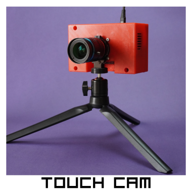
Touch Cam - A Raspberry Pi Camera

Made by mukesh-sankhla / 3D Printing / Displays / Games & Gaming / Photos & Video / IoT
About the project
Touch Cam - A 3D Printed Raspberry Pi Camera
Project info
Items used in this project
Hardware components


View all
Software apps and online services
Hand tools and fabrication machines
Story


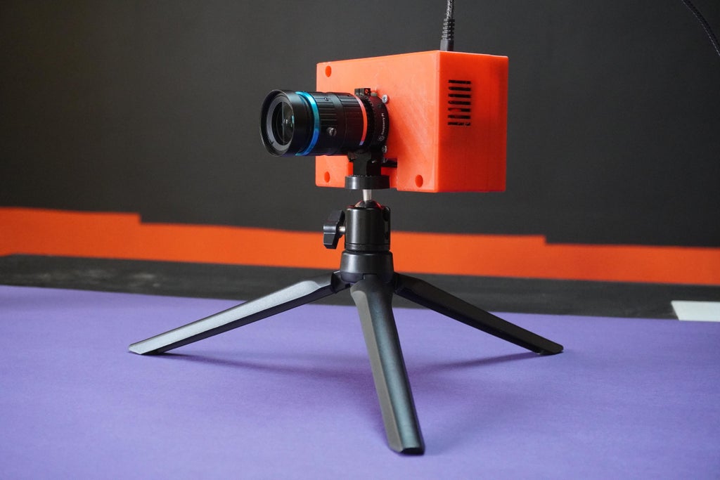
The Touch Cam is a redesigned and enhanced version of the Pi Cam - A Raspberry Pi Desktop Camera Server, integrating a touch display and touch sensor for an intuitive and interactive user experience. This project combines the power of Raspberry Pi with a custom CAD redesign and an innovative touch interface, allowing users to conveniently capture photos, videos, and time-lapse sequences.
Key Features:
1. Touch Display: The Touch Cam features a high-resolution touch display, providing a visual interface for camera controls, image previews, and video playback. With the touch display, users can easily navigate through menus, and view real-time images and videos.
2. Touch Sensor: A touch sensor has been incorporated into the design, enabling seamless operation for capturing photos and starting time-lapse sequences. By simply tapping the touch sensor, users can initiate the desired camera function, whether it's capturing a single photo or starting a time-lapse sequence.
3. Raspberry Pi Desktop Camera Server: The project leverages the computational capabilities of Raspberry Pi to serve as a versatile camera server. The Touch Cam provides a web-based interface accessible from any device connected to the same network, allowing users to remotely control and access the camera's functionalities for capturing photos, recording videos, and creating time-lapse sequences.
4. Cooling System: The Touch Cam is equipped with a 5V cooling fan and heatsinks to ensure efficient temperature regulation. The cooling system prevents the Raspberry Pi from overheating during extended usage, providing reliable performance and stability even in demanding situations.
5. Custom CAD Redesign: The custom CAD redesign not only enhances functionality but also ensures a sleek and functional design, accommodating the touch display, touch sensor, cooling fan, heatsinks, Raspberry Pi HQ camera module and Raspberry Pi within a compact and user-friendly camera enclosure.
6. Easy Setup and Configuration: Setting up the Touch Cam is straightforward, requiring minimal technical expertise. With clear documentation and step-by-step instructions, users can quickly assemble the hardware components, install the necessary software, and start capturing stunning photos and creating time-lapse sequences.
In this tutorial, I will provide a detailed explanation of the designing process using Fusion 360 for the Touch Cam project. Fusion 360 is a powerful CAD (Computer-Aided Design) software that enables users to create complex 3D models and designs. By following these steps, you will be able to harness the full potential of Fusion 360 to design and visualize your own projects.
Note: Feel free to further customize and expand the project description based on any additional features or functionalities you incorporated into your version of the Touch Cam or any other relevant details you would like to include.

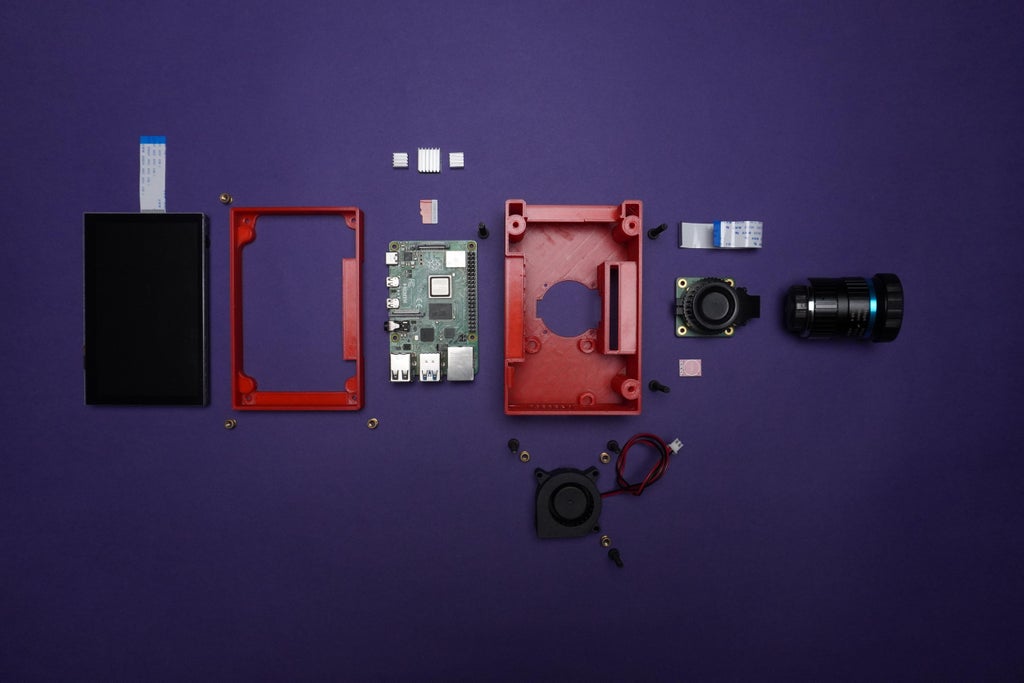
Supplies
Components:
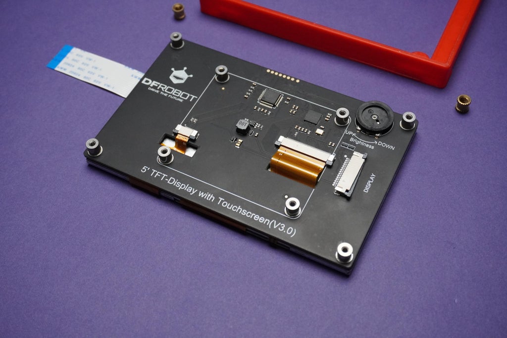
1x DFRobot Raspberry Pi Touch Display
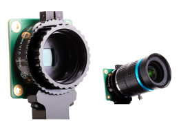
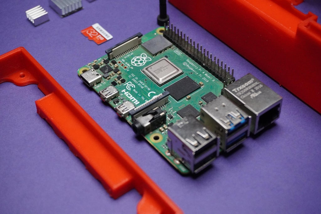
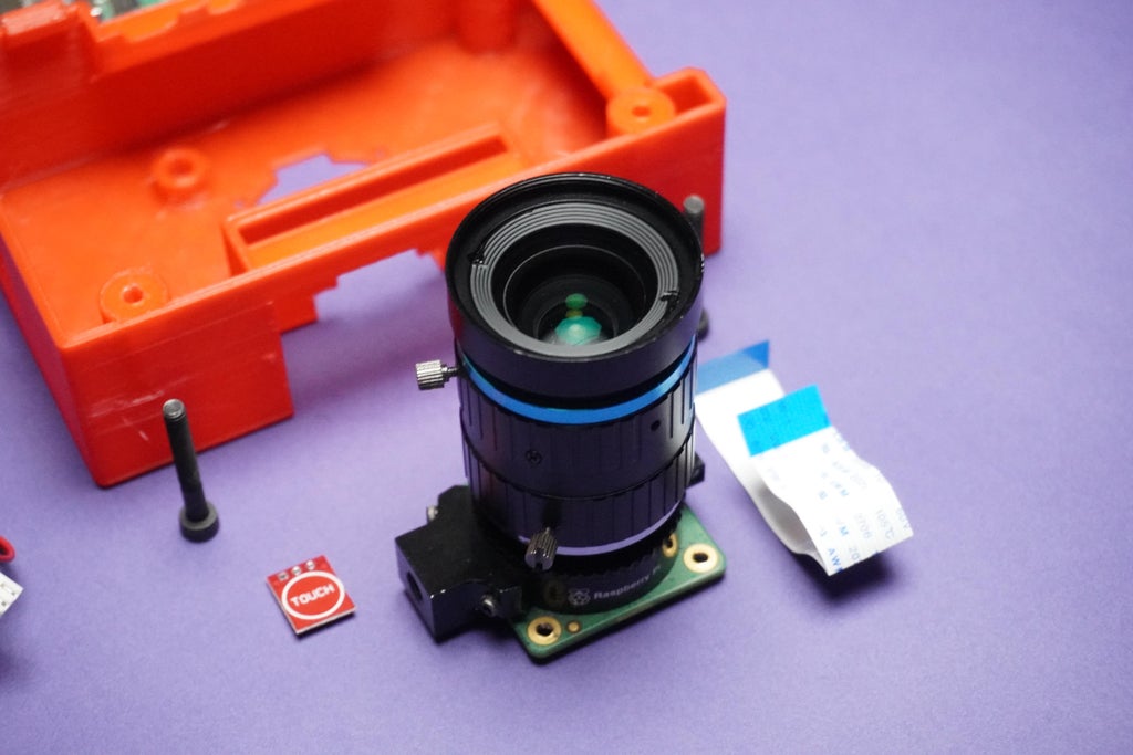
1x Raspberry Pi HQ Camera Module
1x Touch Sensor
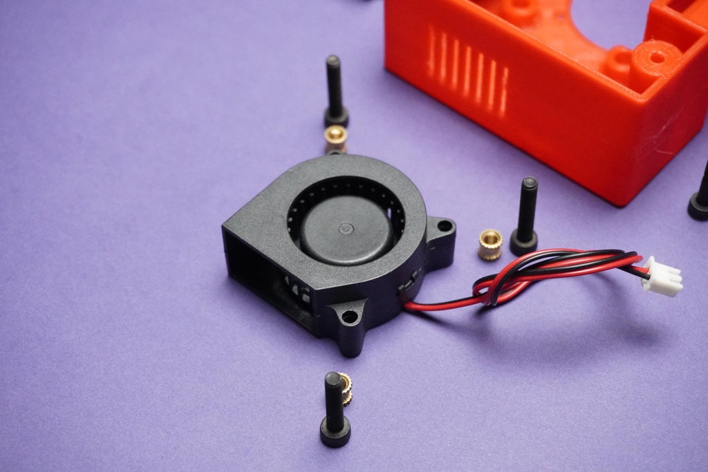
1x 5V 4020 Fan
1x SD Card
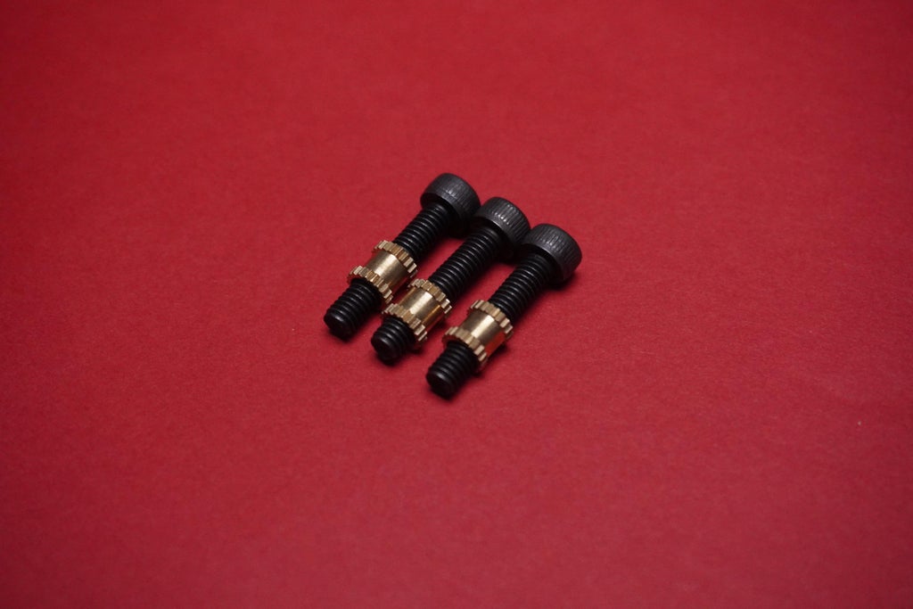
12x M2.5 8mm Screws
Tools:


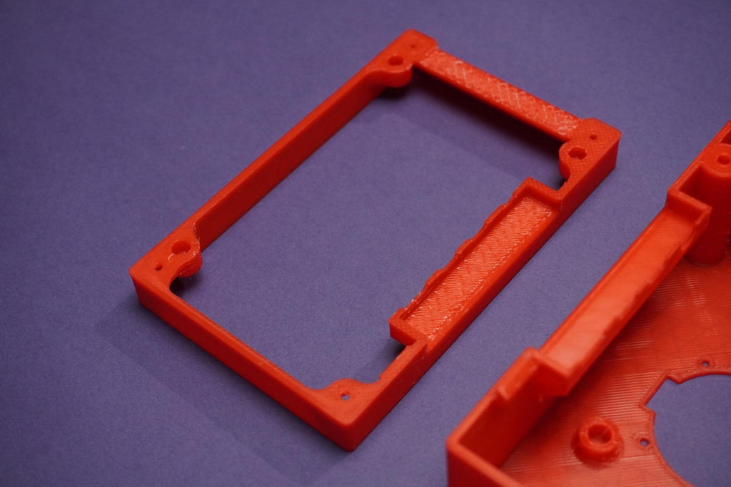
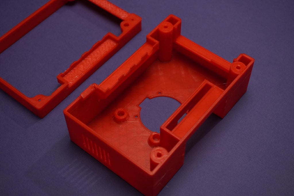
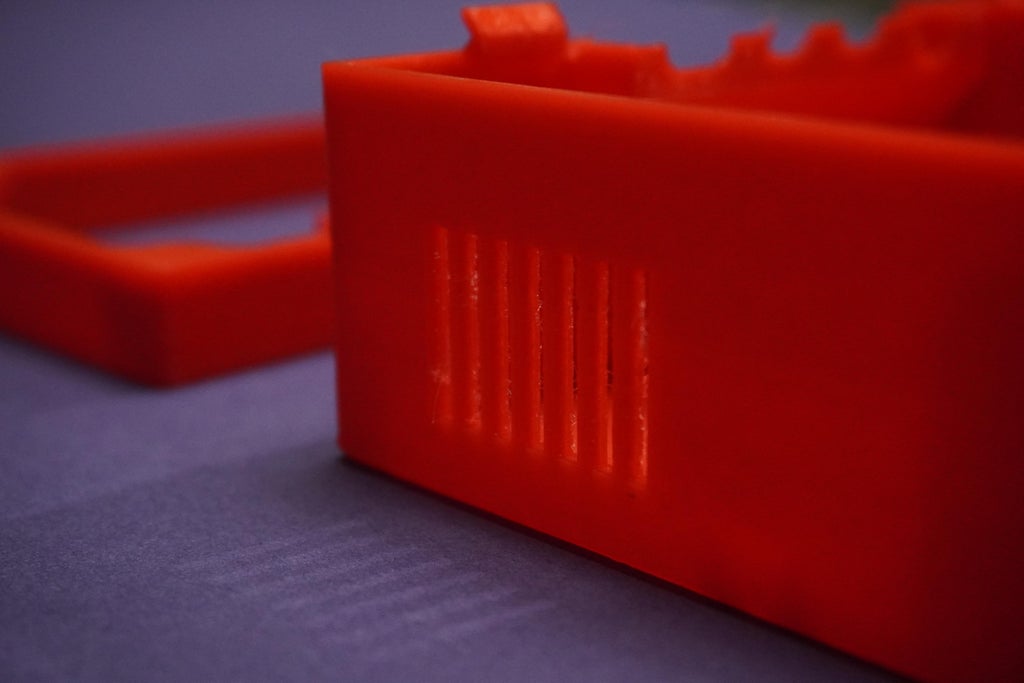
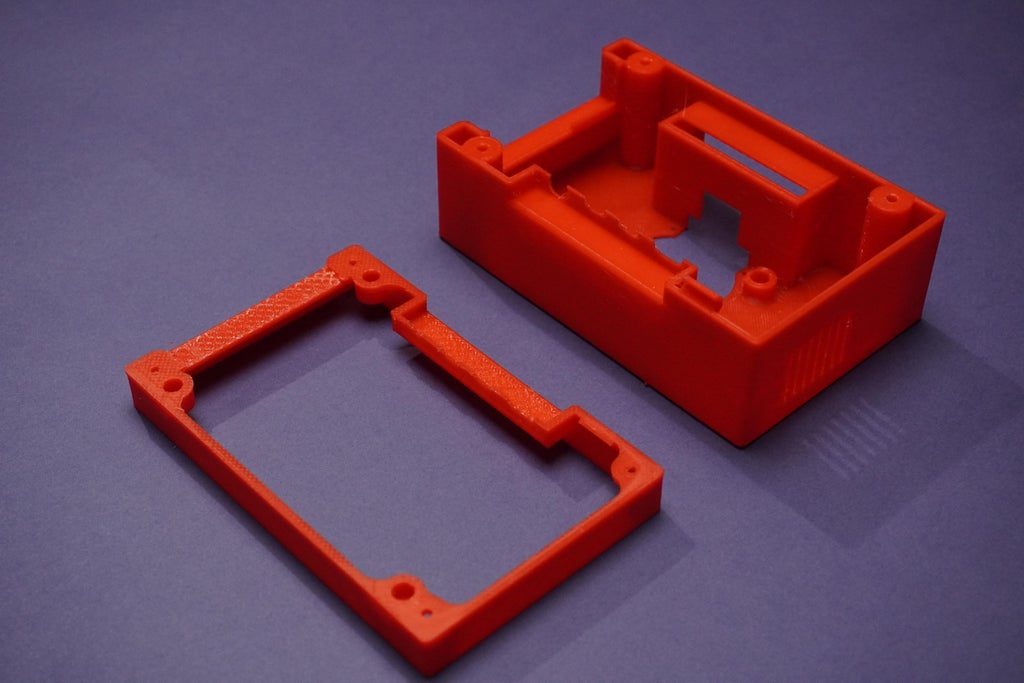
Step 1: 3D Printing
*Download the following stl files and 3D print them
You don't have 3D Printer? Not to worry!
Here I would recommend getting it done from PCBWAY
Why them? They provide the best 3D Printing Service and The quality is just amazing compared to other providers in the market
Get your 3D Printed parts from here https://www.pcbway.com/rapid-prototyping/
Step 2: Assembly Part-1
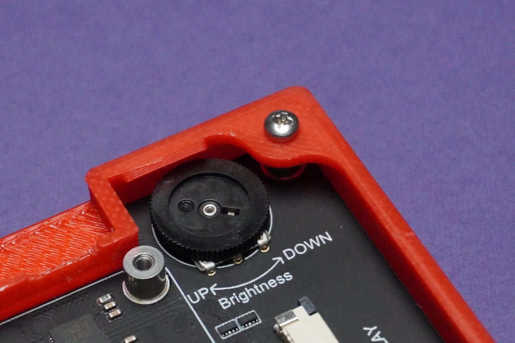
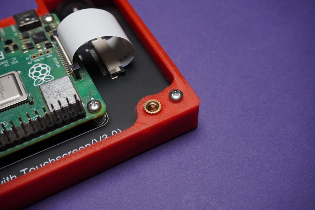
- Put the display into front panel with M2.5 Screws.

- Install the Raspberry Pi Operating System on to SD card using Raspberry Pi Imager Software and insert it into Raspberry Pi.
- I am using Raspberry Pi OS(32-bit) Recommended by the software.
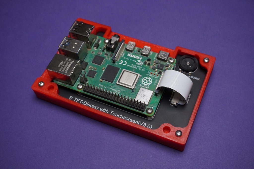
- Then put Raspberry pi onto the screen using screws and connect the display cable that came in the box.
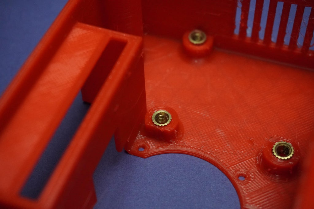
Step 3: How to Use Metal Inserts in 3D Printed Parts
- This step should be done before(Step 20) we installed display and raspberry pi.
- Using soldering iron I heated the metal inserts and inserted them into my 3D prints.

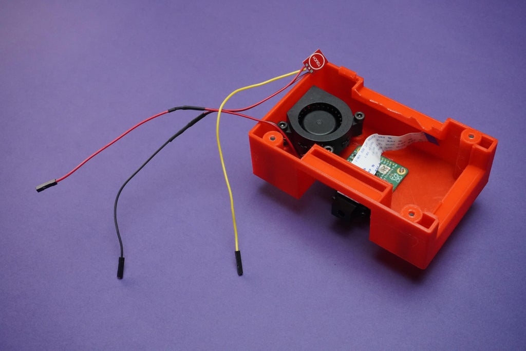
Step 4: Assembly Part-2
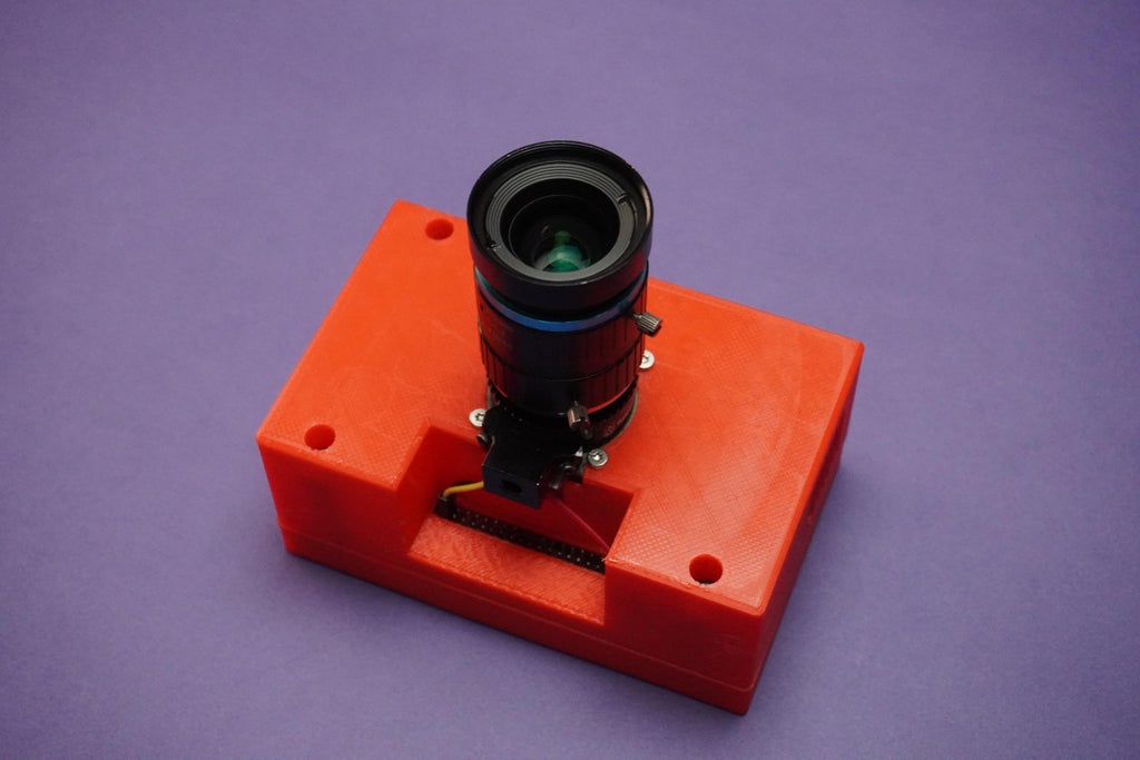
- Fix the Camera module and fan in their places using M2.5 screws and M3 screws.
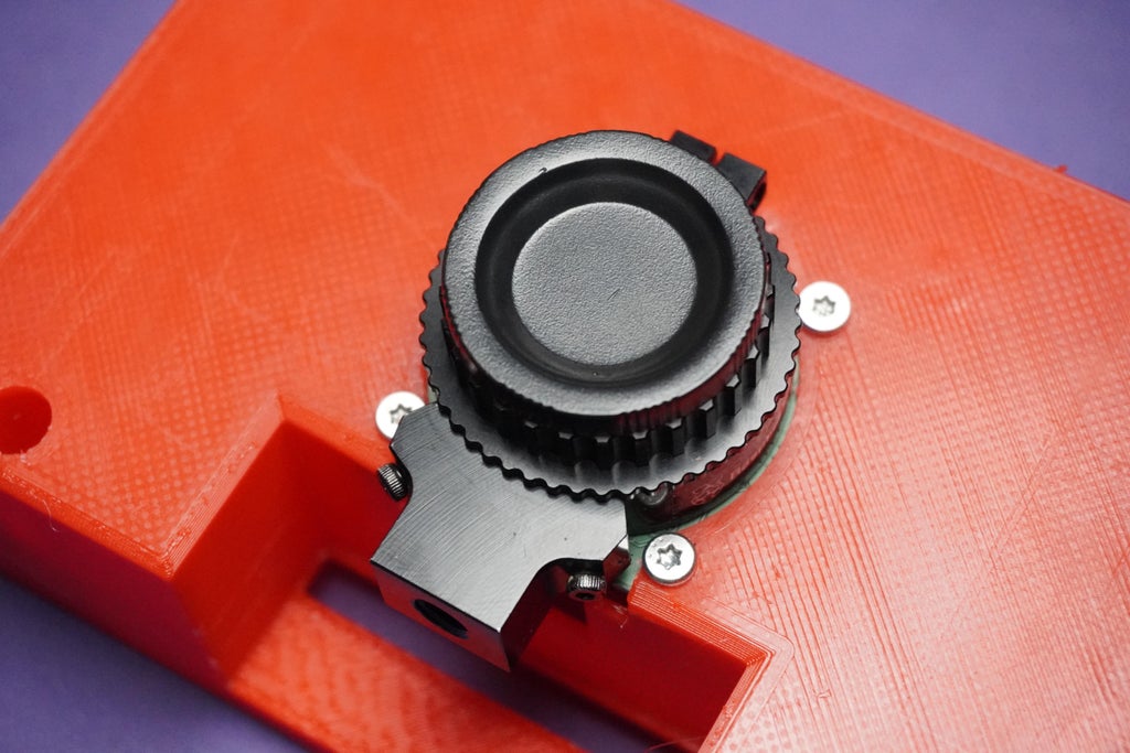
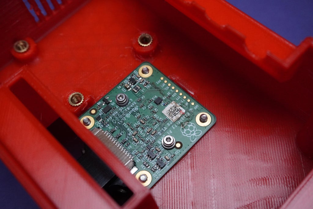

- Connect the camera cable from outside and tuck it inside.


Step 5: Circuit Connections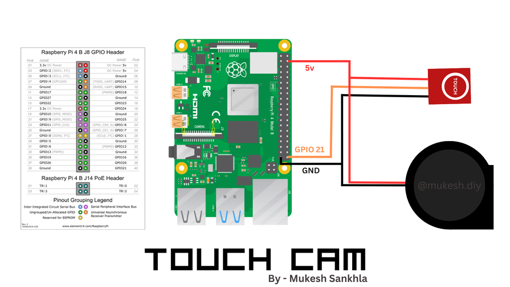
- Make the connections as shown for touch sensor input and powering the fan.
Step 6: Assembly Part-3
- I have used no masking tape to put the sensor.

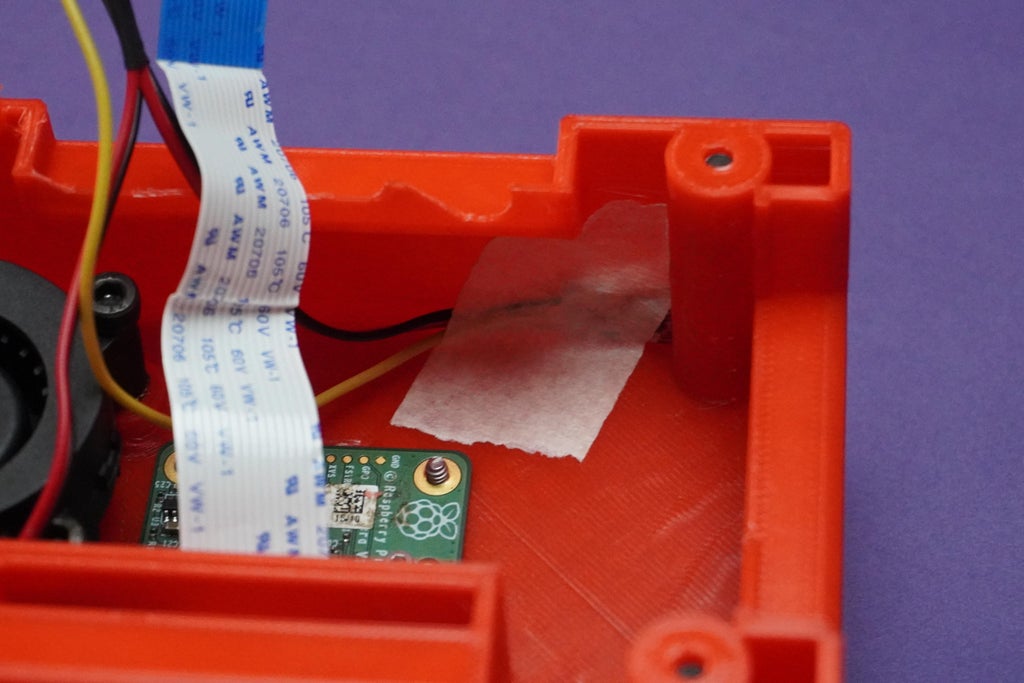
- Now assemble everything together using M3 screws and connect the wires.


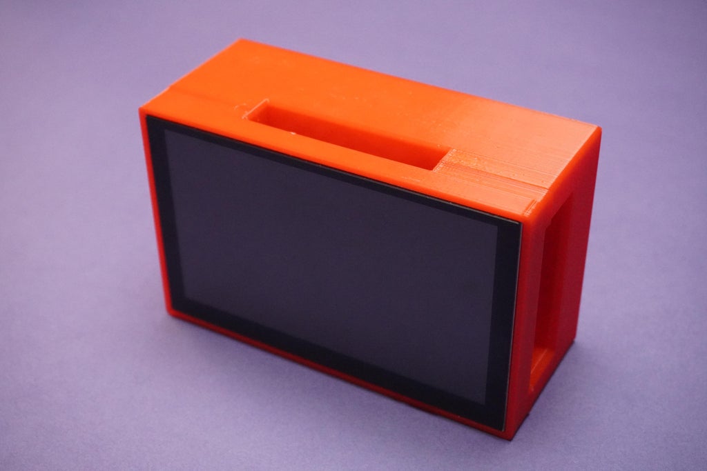
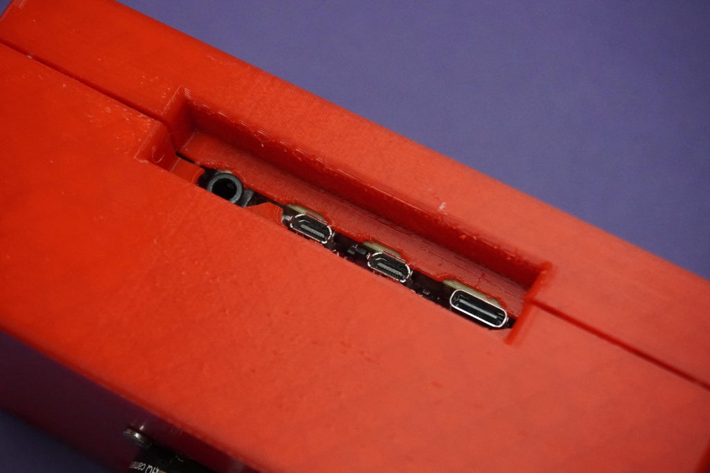
- There is a error of 2mm in the design because of which I have to adjust the Ports opening by trimming the plastic. But don't worry for you I have fixed this error in My stl files download from step19.

Step 7: Software Setup
*Copy the below code into Raspberry Pi and save it as Any_File_Name.py or Click to Download
- import RPi.GPIO as GPIO
- import time
- from picamera import PiCamera
- # Set the GPIO mode to BCM
- GPIO.setmode(GPIO.BCM)
- # Set up GPIO pin 21 as input
- GPIO.setup(21, GPIO.IN)
- # Create an instance of the PiCamera
- camera = PiCamera()
- def capture_picture():
- # Get the current timestamp for the picture filename
- timestamp = time.strftime("%Y%m%d%H%M%S")
- image_filename = f"picture_{timestamp}.jpg"
- # Capture the picture
- camera.capture(image_filename)
- print(f"Picture captured: {image_filename}")
- try:
- # Start the camera preview
- camera.start_preview()
- while True:
- # Check if GPIO pin 21 is high
- if GPIO.input(21) == GPIO.HIGH:
- # Call the capture_picture function
- capture_picture()
- # Add a small delay to avoid excessive checking
- time.sleep(0.1)
- except KeyboardInterrupt:
- # Stop the camera preview
- camera.stop_preview()
- # Clean up GPIO on program exit
- GPIO.cleanup()
- Open the code in Geany and run it.*If you get any error it might be because of picamera python package not installed, to solve this put the following command in terminal.
- pip install picamera
- Now you can run the code successfully.
- The functionality of this code is when we run it will start camera preview and when we touch the sensor it will capture the photo and save it to the same directory as the python code.Open the code in Geany and run it.
- If you get any error it might be because of picamera python package not installed, to solve this put the following command in terminal.pip install picamera
- I would personally recommend you to use the software from My Previous Pi Cam - a Remote Raspberry Pi Desktop/Camera/Server
- Follow the instructions from Step 8 of the Pi Cam to set the remote.it platform on raspberry pi for remote access.
- With this software setup you would be able to access your Raspberry Pi and its camera remotely from any desktop and handhelds, you can also access the camera interface directly from bowser and photos, videos, timelapse directly to your device this makes everything easy and hassle-free, no codes and no further commands.
- Just after setting up the software bookmark localhost:80 into your Raspberry Pi's Browser and run the browser in full screen mode by clicking the 3dots on right hand side corner.
Raspberry Pi Camera Web App UI Demo

Photos/Video Samples:


Click here to refer the full CAD design guide.
I hope you found this tutorial help full, if so please let me know below in the comments. If you have any questions or suggestion, please feel free to drop down below.
Thank You!
See you with another project ;)
Schematics, diagrams and documents
CAD, enclosures and custom parts
Code
Credits
mukesh-sankhla
Tech Educator | Content Creator | Developer | Maker - Simplifying technology through hands-on learning. Creating high-quality tutorials, projects, and insights on electronics, IoT, robotics, CAD, 3D printing, and software development at Empowering students, professionals, and makers with practical, accessible, and inspiring content.
Related products


Leave your feedback...