
Timer Display With Nodemcu

Made by santronix / Displays / Home Automation / Kids & Family / Productivity / IoT
About the project
Very simple and quick tutorial on how to make a Timer with OLED display using NodeMCU - the most widely used ESP8266 based microcontroller
Project info
Difficulty: Easy
Platforms: Adafruit, Arduino, NodeMCU
Estimated time: 1 hour
License: Apache License 2.0 (Apache-2.0)
Items used in this project
Hardware components


Story
Today, we’ll take you through a very simple and quick tutorial on how to make a Timer with OLED display using NodeMCU - the most widely used ESP8266 based microcontroller!
We’ll show you and provide you a working code to explain how can you make scrolling text in all directions, how to display your own logo and how to start timer and show it on the OLED display.
The things that you need here are
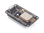
- NodeMCU microcontroller
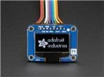
- Adafruit OLED 0.96’’ Dual colour display (you can also use a single color or multicolour display, just make sure you have driver available)
- Male to male jumper cables
- A breadboard
- A computer with Arduino IDE installed
And most importantly your imagination to further explore multiple possibilities and innovate for your designated application.
So lets go….. lets get started….
First of all get all the hardware and software that are required for this small project, you can purchase these hardware from Amazon or any electronic shopping sites. For your convenience we are providing you quick links to purchase these in the description of this video.
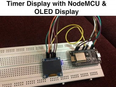
Now once you have them all ready with you, put the OLED display and NodeMCU as shown here in the circuit diagram and in the actual video. The important connections between OLED display and NodeMCU are as I am going to tell you now
- Connect VCC of display to 3V of NodeMCU
- Connect Ground of display to ground of NodeMCU
- Connect SCK of display to D5, SDA to D7, RES to D3, DC to D2 and CS to D6 of node mcu.
In some displays you might not have CS pin for display like in my case I didn’t have that so I just ignored it.
That’s it! Now the connections are ready!
Now let me take you through a code and explain it step by step…
Watch our Youtube video for full instructions on hardware connections and Arduino code walkthrough
Schematics, diagrams and documents
Code
Credits
Related products


Leave your feedback...