
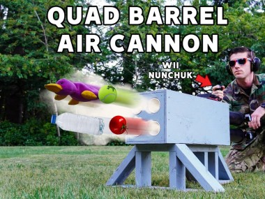
The R0m4 Quad-barrel Air Cannon

Made by hardwareunknown / Fire & Pyrotechnics / Sports
About the project
You've seen air cannons as t-shirt launchers, potato guns, and more. Step your launcher game up with an Arduino Nano and rapid-fire action!
Project info
Difficulty: Moderate
Estimated time: 3 days
Items used in this project
Story
Attention recruit, Major Sergeant Private Major here! You're about to discover the sheer brilliance that is the R0M4; the ULTIMATE in pneumatic PVC launcher technology! Before you're ready to build one yourself, you first need to get acquainted with the launcher. Watch the following demo video and enjoy all the ridiculous launches it's capable of.
R0M4 Quad-Barrel Air Cannon Demo - Lots of ridiculous launches!Now that you're familiar with the R0M4, you're ready to make one for your own use. The following build video describes the bulk of the process. Be ready for some customization to really make it your own, it's encouraged! You should be able to adapt the electronic control system to any launcher you can think of.
How to Make the R0M4 Quad-Barrel Air Cannon*** DISCLAIMER ***: As mentioned in theabove video, PVC IS NOT DESIGNED TO HOLD PRESSURIZED AIR. When PVC fails, it fails catastrophically (ie. it explodes). This can cause serious injury or death. I do not claim that building a cannon like mine (even by following my directions exactly) will mean that you are safe using it. THERE IS NO WAY TO MAKE PVC 100% SAFE WHEN IT IS PRESSURIZED WITH AIR. Ambient temperature, glue joint quality, fill pressure, projectile type, loose wire nuts, improper solder connections, bugs in your code, acts of God, and numerous other factors can all contribute to a cannon's failure. I've done all I can to make you aware of potential safety issues via text and spoken warnings, as well as safety demonstrations in the video. Having said that, you can still be injured orkilledas you build your cannon and while you use it once it's completed. I'm assuming my own risks in building and using this cannon and you need to do so as well if you choose to make your own. Check your local laws before making an air cannon, as some cities, counties, and states do not allow them.
--- Parts and tools I used ---
You may find certain items cheaper at Home Depot (sprinkler valves, screws, PVC pipe/fittings/cement, etc). I've provided links for those items for anyone who doesn't have convenient access to a hardware store.
- Cannons/launcher -
PVC pipe (Schedule 80 strongly recommended!!) - we used 2.5" for the barrels and 3" for the air tanks, length is up to you... bigger tank = more power
Sprinkler valve: https://amzn.to/3jelI3C
Solenoid valve: https://amzn.to/3h5ledf
J-B Weld: https://amzn.to/3gU33sb
PVC primer and cement: https://amzn.to/35Vyufy
1/4" NPT tap and 7/16" drill bit: https://amzn.to/2U3NyoO (you can buy a tap handle, but you'll need a large one... 1/2" I believe, I used vice grips)
1/4" NPT coupler, male: https://amzn.to/3dfbdZU
Pressure gauge: https://amzn.to/3vVtEJV
Schrader fill valve: https://amzn.to/2U502w7
3in wood screws: https://amzn.to/2UIn9NB (for stand)
Spray paint: https://amzn.to/2TeYcca
Sandpaper: https://amzn.to/3x1Z3eQ
Dual-lock: https://amzn.to/2UN1dkp (for attaching battery, can also use velcro or a strap)
Plywood (we used 1/2")
Two 2x4s
Various wood screws (for enclosure)
- Electronics -
Battery: https://amzn.to/3zZOP0n
Momentary push buttons: https://amzn.to/3jpG6iv
Wire nuts: https://amzn.to/3zUirw9
22AWG stranded wire: https://amzn.to/3dkN4Bc
Power plugs: https://amzn.to/3A6d11t
Heat shrink: https://amzn.to/3A1sxeF
- Circuit board -
Circuit boards: https://amzn.to/3vX3NRO
Headers: https://amzn.to/3gY1hGL
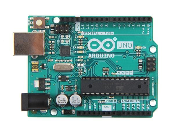
Arduino Nano: https://amzn.to/3jcLDsw
MOSFETs: https://amzn.to/2TVselb (I used IRLZ44N MOSFETS on my final build, but these are similar and worked fine during prototyping, plus they're cheaper on Amazon)
Resistors: https://amzn.to/2UIjCPl
Diodes: https://amzn.to/3xUKlX8
Screw terminals: https://amzn.to/3A0UTpu
22AWG solid wire: https://amzn.to/3haZlJz
Power jacks: https://amzn.to/3y0absD
Screws: https://amzn.to/3wUexS9
LED toggle switch: https://amzn.to/3gR3ELo (optional, used in my build, not shown in this writeup)
Threaded inserts: https://amzn.to/3A5zdsl (optional, used in the 3D printed circuit board enclosure)
- Tools -
Soldering iron: https://amzn.to/3dfthmY (funny colors, great performance for an inexpensive iron, a go-to for hobbyists)
Solder: https://amzn.to/3xRtNPP
Drill: https://amzn.to/3jjH6Va
Diagonal cutters: https://amzn.to/2U7tNg4
Wire strippers: https://amzn.to/3qrEwhr
Helping hands: https://amzn.to/3jcJ89A (not necessary, but they can make soldering easier and more comfortable)
Solder fan: https://amzn.to/3A4jnhy (carbon filter doesn't do much, but the fan helps direct fumes away from your face)
3D printer (for the circuit board enclosure; optional, you can also make the enclosure out of plastic sheets)
- Other items (optional) -
NRF24L01: https://amzn.to/3xRMhiY (used for making a wireless controller, which is beyond the scope of this writeup)
As an Amazon Associate I earn from qualifying purchases through links in my descriptions and comments. This helps me finance future videos and project writeups at no additional cost to you. If you choose to support me in this way, thank you.
------------------
Step 1) Build four air cannons, without the trigger/handle. The following video goes over the entire process of building and testing step-by-step. If you'd like to replicate our build, refer to the PVC section in the diagram below for the dimensions we used.
How to Make a Simple Air Cannon

Cannon and main enclosure dimensions
Step 2) Add solenoids to the cannon sprinkler valves. Careful not to strip the sprinkler valve plastic by over-tightening the male NPT coupler. Make sure to attach the inlet to the coupler (for the valves linked, it's the side with the larger, centered hole).

Solenoid inlet
Step 3) Test your cannons. Fill the tanks with 10-15psi of pressure, hook up a solenoid to the battery using wire nuts, then turn the battery on. The cannon should not release any air before the battery has been turned on, and should release air instantly upon battery activation. Repeat for each cannon to make sure everything works.
Step 4) Decide on your control scheme. If you choose Level 1 (four buttons, one for each barrel), you're set to go... just follow the video's instructions, then skip to Step9, creating/modifying the circuit board enclosure to simply house the wire nuts and button rather than a circuit board.
If you'd prefer Level 2 (a single button controlling all four barrel), you'll need to make a circuit board.
Level 3 involves a wireless controller like the Wii Nunchuk shown in the project thumbnail, however that controller has been discontinued and is difficult to find. Wireless controllers are outside the scope of this writeup so I won't be going over them here. Feel free to play around with controllers and your Arduino, though, and work on implementing one for your build if you'd like! For a coding example, check out my personal cannon's code.
Step 5) Lay out your components according to the following diagram, then bend the leads slightly so they stay in place for soldering. We're using a 26 x 31 point dual-sided perfboard for ours (one of the 7cm x 9cm boards from the linked assortment). The Arduino Nano is there as a visual only; you won't be soldering that directly to the perfboard. Solder male header pins to the underside, then use those to place female header pins on the perfboard (that way the Nano remains removable for easy programming/using in other projects).

Circuit board component layout
------------------
A quick break-down of the components for those who are curious (if you don't care about how the circuit works and just want to continue the build skip to Step 6):
a) The Arduino Nano serves as the brains of the launcher, reading the button signal and telling the launcher to fire.
b) The MOSFETs (the RFP30N06LEs or IRLZ44Ns) are transistors that allow current to flow from the power jack to the screw terminals when they receive a signal from the Arduino. The solenoid valves will open because of this current, causing the associated cannon to fire.
c) The 220 Ohm resistors are "gate resistors". They limit the current to the MOSFETs so as not to damage the MOSFET gate (the pin that receives the signal from the Arduino).
d) The 100k Ohm resistors are "pulldown resistors". They pullthevoltagedown at the MOSFET gates when the Arduino signals have been switched off. These helps ensure the MOSFETs are fully turned off when they should be, rather than left "floating".
e) The diodes (the 1N4001s) are functioning as "flyback diodes". Flyback diodes are used to eliminate flyback, which is a voltage spike that occurs across an inductive load (like a solenoid) when the supply current is suddenly reduced or interrupted (in our case, turned off).
Basically, when the solenoid is activated, all is good. The current flows from the positive terminal of the power battery, through the solenoid valve (opening it), to the negative terminal. When we switch off the battery, the solenoid quickly closes. Because the solenoid uses an electromagnetic field to remain open, that field collapses which can then send a voltage spike back through the circuit, damaging it. A flyback diode prevents damage to the circuit by providing a one-way route for this voltage spike to dissipate, hence why the diode is oriented to only allow current to flow from negative to positive in the wiring diagram of Step 6. This orientation matters, so makesure it's placed this way.
f) The screw terminals allow us to easily connect the buttons and solenoids after mounting everything to the launcher enclosure. As good practice, you should not solder anything to circuit boards that can move/bend the connecting wires. Too much movement can cause the solder connections to break, causing the circuit to not work, or worse, short circuit and damage something.
------------------
Step 6) Add wires according to the following diagram and legend. Use solid core wire for any connections on the board (stranded wire is used for attaching the solenoids and button to the screw terminals). The curved wires do not actually extend past the board. They are curved only to make the connection points easier to identify. The pinouts for both the RFP30N06LE and IRLZ44N MOSFETs are the same, so the wiring remains the same for either.

Circuit board wiring
Step 7) Solder the components and wires. Remember, the connections made to the Arduino Nano are actually being made to the female header pins. The Nano should remain removable from the board.
Step 8) Upload the code from the attached.ino file to your Arduino Nano and place it into the circuit board headers. Make sure you orient it in the direction shown in the diagram. Orienting it backwards could cause damage to the Nano and/or your circuit board.
*** DISCLAIMER ***: I am a hobbyist, not a programming professional. I am providing the code in the.ino file as an example of what you can use for your cannon. IT IS NOT GUARANTEED TO BE BUG-FREE. Also, be careful with your soldering in order to avoid solder bridges/short circuits. Both the code, as well as solder bridges/short circuits in certain places, COULD CAUSE YOUR CANNON TO FIRE WHEN YOU DO NOT INTEND IT TO, EVEN WITHOUT YOU PHYSICALLY PUSHING THE FIRE BUTTON/TRIGGER/ETC., CAUSING DAMAGE, INJURY, OR DEATH. Make sure you test the code, as well as your completed soldered board, with the cannons depressurized to ensure they work as intended before adding any air pressure. This does not guarantee your safety, but it may reduce the risk of injury. I'm assuming my own risks using this code/wiring diagram and you need to do so as well if you choose to use either yourself.
Step 9) 3D print the attached circuit board enclosure and grommet pieces and add inserts to the enclosure. You'll need to add a hole for the button as I did not initially use one. You'll also notice a number of holes that are seemingly random. I used these for LEDs and a wireless controller receiver in my custom version, so you can ignore those.
If you don't have access to a 3D printer you can use an online service such as Shapeways to print the enclosure, or simply make your own simple enclosure out of plastic sheets, and you can purchase pre-made rubber grommets online. Drill a hole and attach your button to the enclosure, install the button wires into the proper screw terminal, the loosely mount the circuit board to the enclosure (you may need to remove the board when installing the solenoid wires later on).

Circuit board terminals
Step 10) Design and cut the pieces for your enclosure and support blocks. Refer to the quad cannon build video for how to make the supports, as well as the wood sections in the diagram below for the dimensions.

Cannon and main enclosure dimensions

Main enclosure and supports
Step 11) For the bottom half of the launcher, screw on the large single-sided support blocks, mount your cannons, secure them in place with the small support blocks, then add the dual-sided support blocks. Repeat this step for the top half of the launcher, but without the dual-sided support blocks. You may want to add an additional screw to the middle of the enclosure halves for rigidity.

Mounting the cannons

Middle screw added for rigidity
Step 12) Use gaffer tape to fine-tune the fit of the cannons, if necessary.

Adding gaffer tape
Step 13) Drill a 5/8" hole for the solenoid wires in the top half of the main enclosure. Press the grommet body through the hole, then super glue the grommet ring to the other side to secure the grommet in place.

Solenoid wire hole with grommet installed
Step 14) Cut pieces from the 2x4s according to the following diagram, then screw them together at each joint using 3" screws to create your stand.
")
Stand (front section on the left, rear section on the right)
Step 15) Screw your stand to the enclosure through the bottom plate, and paint your cannon if desired. 2-in-1 paint and primer works decently for both the wood and PVC, although you may want to sand the glossiness from the PVC first, paint it, then follow that up with a clear coat to protect the paint.

Screw the stand to the main enclosure

2-in-1 paint and primer + sanding + clear coat works well
Step 16) Feed the solenoid wires through the hole in the top half of the enclosure, then screw the enclosure halves together.

Feed the solenoid wires through the enclosure hole

Screw the main enclosure halves together
Step 17) Install the solenoid wires into the remaining screw terminals, secure the circuit board to the enclosure, then mount the circuit board enclosure to the main launcher body.

Circuit board terminals
")
Install solenoid wires (toggle switches/LEDs were custom for my cannon; not shown in writeup)

Mount the circuit board enclosure
Step 18) Mount the battery with a strap, velcro, or Dual-Lock strips, then connect it to the circuit board.

Dual-Lock strips on battery

Connecting battery to the circuit board with power cable
Congratulations, your cannon is complete!
*** DISCLAIMER ***: Before firing your cannon at full pressure, check all your components for their maximum rated pressures, as yours may be different than mine. My lowest max rating is 145psi, so I chose 120psi as my fill maximum. Again, PVC IS NOT DESIGNED FOR COMPRESSED AIR, so make sure you always leave plenty of room above your fill pressure before you hit the lowest maximum. THIS WILL NOT GUARANTEE YOUR SAFETY, but it may reduce the risk of the cannon failing catastrophically.
")
LAUNCH!! (These were dishcloths wrapped in rubber bands to avoid damaging anything)
*** DISCLAIMER ***: Never aim your cannon at people, animals, or property as doing so risks damage,injury,ordeath.
Subscribe to my YouTube channel (Hardware Unknown) for more projects like this, and comment on the build video if you run into any issues/have any questions about the project. I'm very responsive there, and for some reason I don't seem to get comment notifications here on Hackster.
Thanks for watching, reading, and following along with this build. Enjoy your cannon, launch ridiculous things with it, and be sure to share how your build went with me!
Schematics, diagrams and documents
CAD, enclosures and custom parts
Code
Credits
hardwareunknown
I post my build projects on YouTube (youtube.com/hardwareunknown), hoping to entertain, educate, and inspire you to build yourself. Join me.
Related products


Leave your feedback...