
The Dondi Lib: A Bluetooth Low Energy Light Box

Made by jaredwolff / Art / Lights / IoT
About the project
Part nightlight, part art, part Internet of Things. This little bluetooth enabled box will surprise and delight.
Project info
Difficulty: Difficult
Estimated time: 2 weeks
License: Creative Commons Attribution-NonCommercial CC BY-NC version 4.0 or later (CC BY-NC 4+)
Items used in this project
Hand tools and fabrication machines

Story
Part. nightlight, part art, part Internet of Things, this box was born out of wanting to make something pleasing to the eye but also throw some technology in there too.
The original idea was to create a battery powered device that would act like a recording sign, you know one of those signs that you'd see in a studio when a band, radio program, etc. is being recorded. If you can't imagine it, see below. ?
 From Laurel L. Russwurm on Flickr
So after a few months of on and off work. I managed to put together I'm pretty proud of. It's definitely not perfect but it's close to what I imagined in my head. Below it's sitting on a bench in our doorway to greet anyone walking in.
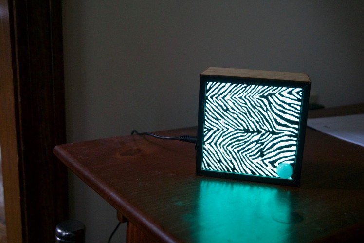 The Dondi Lib in the wild.
It is quite photogenic so I was able to take some good pictures of it. It uses the same RGB scale so any color between rgb(0,0,0) and rgb(255,255,255) is possible. The round dome in the bottom right hand corner is the lens for the movement/PIR sensor.
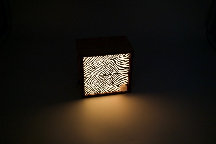 It can do a few colors..
Plus, with some React Native trickery, it can be configured with an app on iOS (and feasibly Android as well).
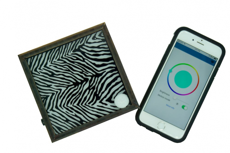 The Dondi Lib and my iPhone living in harmony..
I even made a quick video introduction. Check it out:
Video introduction to the Dondi LibIf you want to join me down the rabbit hole on some of the important design decisions, tricks and tips to get it made continue on down below. If not that's ok too! You can learn more about what I do at Circuit Dojo and also check out my LinkedIn.
If you did choose to keep going, let's not waste any time and get started!
(Note: I'm still working the documentation a bit. Excuse the mess!)
The Circuit Board: LED Placement
One of the big questions to answer at the beginning of the process was where to place the LEDs. I could place 50 or I could place 2. How many I needed was dependent on the light output geometry of the RGB LED.
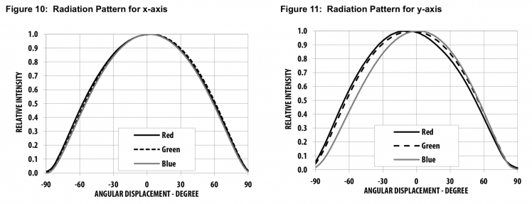
First thing I did was look at the radiation pattern for the X and Y axis. This should give you a clear idea of the strength of the light at all visible angles. Some LEDs advertise their viewing angle to be very wide but usually the bulk of the light passes through the center.
 X and Y viewing angles for this particular RGB LED.
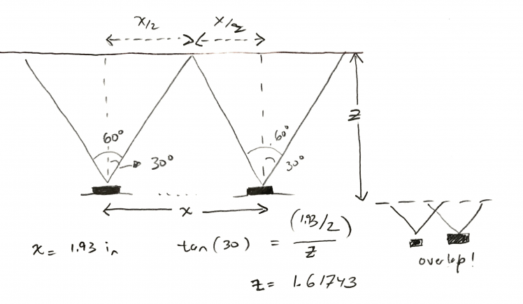
According to the graphs, from -30° to 30° yields 90% strength or better. So, I scratched around on some paper to really understand what the minimum distance from the tip of the LED to the acrylic should be. The more distance, the thicker the box would need to be. So, striking a balance between thickness and LED count was important here.
Turns out, my initial calculations were a bit off. It’s been a while since high school geometry class. I use the cos instead of tan function but I eventually got to the right answer. (See below!)
 I hated high school geometry class.
Minimally, the LED should be about 1.617 inches away from the acrylic and about 1.93 inches spaced both in X and Y. I kept the X/Y spacing and increased the distance between the tip of the LED and the acrylic to about 1.925 inches. This way, the least bright light should overlap at the edges giving more of of a uniform appearance.
The Circuit Board: Powering Everything
There’s a gazillion ways to power a circuit. Solar panels, batteries, spinning mouse wheel, and plugging it into the wall are just some options to make it happen.
For this project, I knew that the device would either go up on a shelf or even on the wall for extended amounts of time and that a plug may not be accessible. So, engineering in a way to run on a battery plus the ability to operate without wall power seemed like the most logical option.
So, a quick search of the electronic bits in my house, I ended up pulling a battery from one of these Nordic Thingy 52 devices. It's a 1440 mAh battery and it conveniently sits right in the middle of the PCB between the 4 LEDs I discussed earlier.
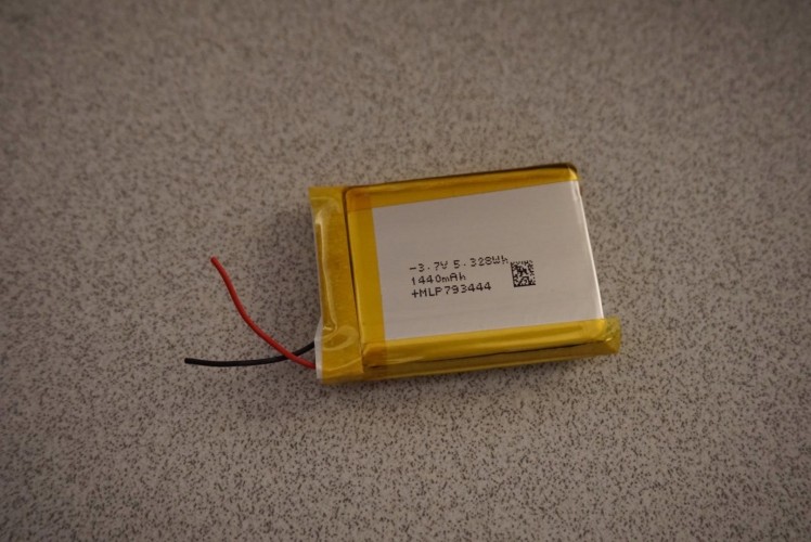 1440 mAh Battery made by McNair in China
Side note: I had reached out to McNair for some quotes with no luck. From what I could telland what I was told by some ex-employees they're focused more on big fish rather than small ones like me.
With knowing how much capacity this battery has, I was able calculate how long I expected the device to last with the LEDs on full tilt. These calculations are very rough but provide a quick and dirty understanding if I'm in the right ballpark:
1 LED = 15mA current
4 * 15mA = 60mA
1440 mAh / 60mA = 24 hours
So a 1.44AH battery may last 24 hours of use.
24 hours of extended use should be good enough in my book. If the device is active maybe 1% of the day, theoretically the operation could extend out to almost 100 days!
Two more important aspects of power are the power supplies themselves. I decided to use an LDO to power the processor and a switching boost to power the LEDs.
For the LDO, the choice was based of of quiescent current and efficiency. If I anticipate the device using very little current in standby, there's almost no use to running a switching power supply in that instance.
For the boost, the idea was to be able to setup the voltage up to about 3.8V. If the input voltage to the boost is higher technically it could be shut down and simply bypassed. If the device was plugged into the wall, again the boost could be bypassed and the LED could receive the (almost) full USB power.
The Circuit Board: Use Off The Shelf
Nothing is fun without the addition of some type of Bluetooth or Wifi. This can be accomplished in two ways:
1. Adding all the discrete components to your circuit board. Tuning antennas and pi-networks. Getting it certified. Crying a little bit.
Or
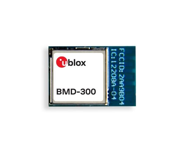
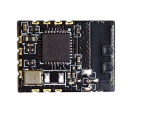
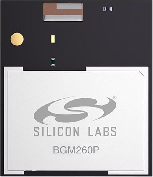
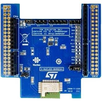
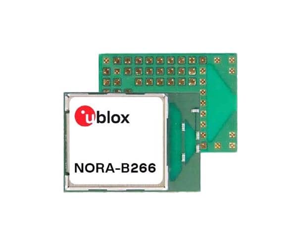
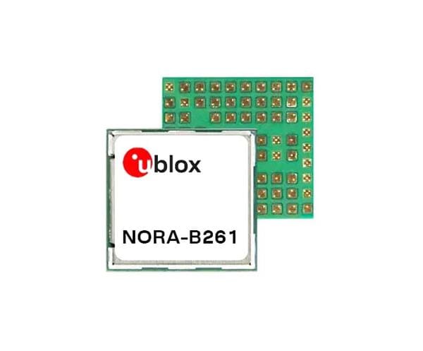
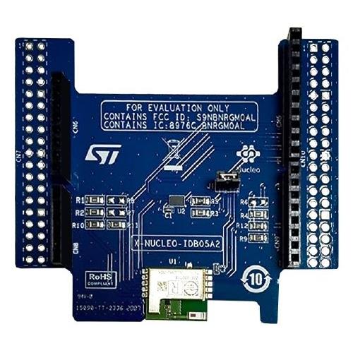
2. Drop a pre-certified module on the board and keep moving!
The advantages of using a module over an on-board design relates to the cost of testing and if you can bear it during your development. I have found, at its cheapest, FCC certification costs $6k! Whereas with a module, you typically don’t need to do any testing. (though Part B spurious emissions testing is recommended)
Plus, when using a module design, you have a boost of confidence that your circuit will work once it's on your customized board because you spent a good amount of time using a development board for that same platform. (Right??... Of course!)
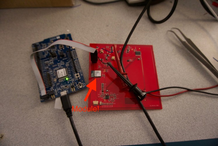 Module on-board!
The Circuit Board: Engineer for the Edges
Creating a device that is robust and works at a different range of temperatures and voltages requires extra attention to detail.
Here are some questions to ask when getting started:
- How will this device work at full battery?
- I'm turning off the boost during this time. Is it working as a pass-through as expected?
- What if it's on? Is there any change in the operation?
- What happens during normal operation? Any caveats to be aware of?
- How will the power supplies perform in lower battery situations? When will I shut off the device? How will the end user know the device is running out of juice?
These questions are tailored to this particular project but they can be adapted for any project really. The idea of this thought exercise is to fully understand what each block of circuitry is doing at a particular battery state or operation state.
Ultimately, the only way to make sure your project is as bug free as possible is to test in all these corner conditions. That's what the big boys like Apple does and that's why the iPhone can be frozen or fried in a frying pan and still work 2 years later.
The Circuit Board: Library Creation
A quick video on Library Management inside EagleCADOne of the more powerful things you can do is create a library of parts that you can go back and re-use over and over. I created a tutorial on how to setup a library for success here.
The process is as follows:
1. Find the part that you’re trying to add. If this type of part already exists in your library you can leverage it in the next step.
2. Create a new part by either copying an old one or creating a new symbol and footprint
3. Edit the part attributes to match the part value, tolerance, manufacturer part number and vendor part number.
4. Drop it in your schematic or use the replace command to replace another similar part.
5. Sending the board to fabrication
The Circuit Board: Saving Cost
One of the biggest things you can do to keep costs low in a project like this is place all the surface mount components on one side. It may not add additional cost in terms of components but it will add cost to the assembly.
Typically, it will require an additional stencil (between $200-400USD here in the good ol’ USA) and the labor to set up and run the pick and place machine on a second side. Plus, it’s also much easier to assemble by hand when you only have one side to deal with. Sometimes, using both sides is necessary but in this project it's definite overkill.
I also wanted to try out a newer (or at least new to me) US based PCB assembly service called Macrofab. My curiosity was peaked when I saw that the costs were reasonable. The catch? The lead-times were just a tad bit longer than typical. As a comparison, I typically can get boards fabricated and assembled in 2 weeks. Macrofab took over a month. By the end of that month, to say the least, I was ready to get to work.
I did take some screenshots of the quotes I received from Macrofab for this project. This was for both the fab and assembly for two circuit boards. You can see it down below for reference.
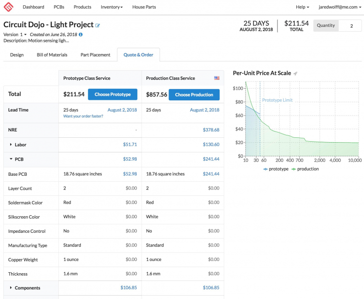 Macrofab Quote
Thanks for the optimization I did when creating my library in the earlier steps, It was much easier to upload my board file to Macrofab and for them to parse the information that was already there. The only part that sucked was going through any parts that were out of stock and picking alternatives. ?
If you're curious, here's how everything looked before fab and assembly:
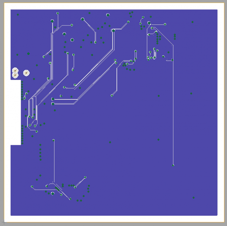 Back side
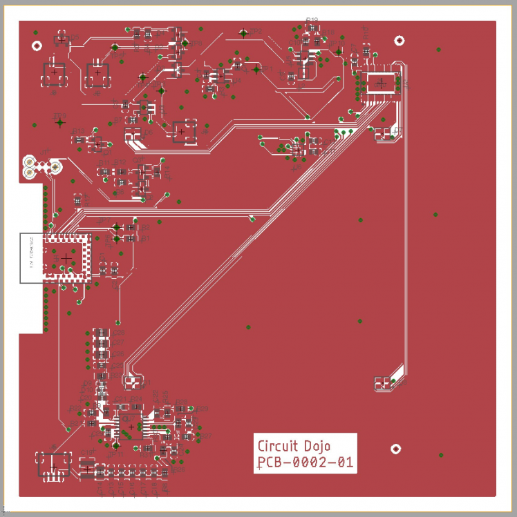 Front side
That's it for this first part. If you like everything so far, subscribe to my newsletter here for biweekly updates, new posts and videos. ??
Schematics, diagrams and documents
Code
Credits
Related products


Leave your feedback...