
Smart Shipment With Tinyml

Made by timothy_malche / Artificial intelligence / Displays / Home Automation / Robotics / IoT
About the project
Developing a TinyML solution for the Shipping Industry that allows users to track the status of a shipment/package in real time.
Project info
Difficulty: Difficult
Platforms: Amazon Web Services, Arduino, M5Stack, Neuton Tiny ML
Estimated time: 2 weeks
License: GNU Lesser General Public License version 3 or later (LGPL3+)
Items used in this project

Story
Artificial Intelligence (AI) and Machine Learning (ML) enable us to solve most of our everyday problems efficiently, giving us the power to create intelligent devices that can make decisions by themselves in real time. In this project, I'd love to demonstrate how TinyML (Tiny Machine Learning) works for a global industry such as Smart Shipment.
With the help of my project, users will be able to track the status of their package/shipment whether the package/shipment is:
- moving
- stationary
- impacted
- thrown
- picked
- placed in the wrong position
There may be more classes for STATUS of a package and not just limited to those mentioned above. First, let's watch a video demo to see how it works:
Smart Shipment Project DemoWhy is it important?Consumers always want to keep track of their packages and their proper handling during shipment. As such, tracking the status of the packages enables users to make sure that everything will arrive safely.
How does this work?The project "Smart Shipment" is based on the Internet of Things (IoT) and Artificial Intelligence (AI). With the help of AI, the status of a package can be identified. IoT is used to send the status in real time to a cloud server which can be accessed via a Web App over the Internet.

A TinyML model is embedded in a microcontroller (MCU). Each package/shipment consists of an MCU. The inferencing occurs on the device itself and the result is transmitted to the server as a simple text stream.
This approach, when the machine learning model is run on the device (and not in the cloud), allows you to significantly reduce the amount of information sent to the cloud. As such, we send only triggers of the changed state to the cloud instead of constantly sending data to determine the state (which usually increases the cost in such projects.).
RequirementsThe required hardware and software to build this project include:
Hardware Requirements
- Processor: MCU
- Sensor: Accelerometer, Gyroscope
- Communication: WiFi, GSM, NB-IoT/LTE-M, LoRa
Software Requirements
- Neuton.ai
- Arduino IDE
- Visual Studio Code
- MQTT Broker
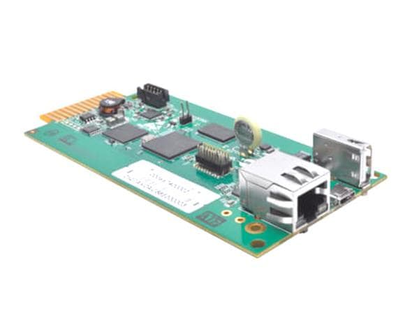
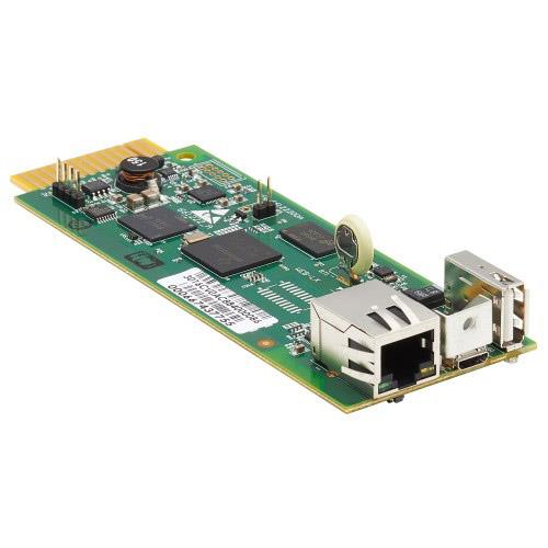
Any MCU can be used for this project as the TinyML model built with Neuton.ai can be embedded and executed on all types of MCUs. For this project, I will use M5Stack Core 2 AWS IoT Kit which is an ESP32-based MCU. It has the following features:
- ESP32-D0WDQ6-V3, supports 2.4GHz Wi-Fi
- 16M Flash, 8M PSRAM
- Built-in ATECC608 hardware encryption chip
- Capacitive touch screen
- Built-in PDM microphone, power indicator, 6-Axis IMU, vibration motor, I2S codec, Amplifier, Speaker, RTC, power button, reset button, 10 x RGB LEDs
- TF card slot (support up to 16GB)
- Built-in 500mAh Lithium-ion battery
Source: m5stack.com

Source: m5stack.com
SensorsThe accelerometer and gyroscope sensing units are required for this project. Accelerometers measure linear acceleration along with one or several axes. A gyroscope measures angular velocity. To track the status of this package, these sensors are utilized to measure linear acceleration and orientation.
Source: https://www.maximintegrated.com/en/design/technical-documents/app-notes/5/5830.html

Source: https://www.maximintegrated.com/en/design/technical-documents/app-notes/5/5830.html
M5Stack Core 2 AWS Kit is built in 6-Axis IMU (Inertial Measurement Unit) Unit MPU6886. The MPU6886 is a 6-axis attitude sensor with a 3-axis gravity accelerometer and a 3-axis gyroscope, which can calculate tilt angle and acceleration in real-time.
ProtocolThe data transmission in this project is done using the MQTT protocol. MQTT stands for Message Queuing Telemetry Transport. MQTT is a machine-to-machine Internet of Things connectivity protocol. It is an extremely lightweight and publish-subscribe messaging transport protocol.
MQTT Publish / Subscribe Architecture
Source: https://mqtt.org/

Source: https://mqtt.org/
Steps to build the projectThe Smart Shipment Project requires the following steps:
- Step 1 - Collect Data
- Step 2 - Build a TinyML Model
- Step 3 - Program Smart Shipment Firmware
- Step 4 - Program the Web App
Here's the walkthrough of the steps specified above:
Prerequisite: Please set up Arduino environment for M5Stack Core 2 as specified in this article.Step 1: Collect DataOpen the Arduino IDE and use the following code shipment_data_collection.ino to collect the data.
#include <M5Core2.h>

float accX = 0.0F;
float accY = 0.0F;
float accZ = 0.0F;

float gyroX = 0.0F;
float gyroY = 0.0F;
float gyroZ = 0.0F;

int times = 0;

// the setup routine runs once when M5Stack starts up
void setup(){
  // Initialize the M5Stack object
  M5.begin();
  M5.IMU.Init();
  M5.Lcd.fillScreen(BLACK);
  M5.Lcd.setTextColor(GREEN , BLACK);
  M5.Lcd.setTextSize(2);
}

// the loop routine runs over and over again forever
void loop() {


  // put your main code here, to run repeatedly:
  M5.IMU.getGyroData(&gyroX,&gyroY,&gyroZ);
  M5.IMU.getAccelData(&accX,&accY,&accZ);
  /*M5.IMU.getAhrsData(&pitch,&roll,&yaw);
  M5.IMU.getTempData(&temp);*/
  if(times<=10000){
    Serial.print(accX);
    Serial.print(",");
    Serial.print(accY);
    Serial.print(",");
    Serial.print(accZ);
    Serial.print(",");
   Serial.print(gyroX);
    Serial.print(",");
    Serial.print(gyroY);
    Serial.print(",");
    Serial.print(gyroZ);
    Serial.println();
  }

  M5.Lcd.setCursor(0, 20);
  M5.Lcd.printf("%6.2f  %6.2f  %6.2f      ", gyroX, gyroY, gyroZ);
  M5.Lcd.setCursor(220, 42);
  M5.Lcd.print(" o/s");
  M5.Lcd.setCursor(0, 65);
  M5.Lcd.printf(" %5.2f   %5.2f   %5.2f   ", accX, accY, accZ);
  M5.Lcd.setCursor(220, 87);
  M5.Lcd.print(" G");

  delay(20);
  times+=20;
}
When you execute the code you will see information in the serial monitor as below.
Output on Serial Terminal

Output on Serial Terminal
Copy the accelerometer and gyroscope data from the serial terminal to a text file and save it as CSV.
Using the above code collect the data for the following classes:
- stationary
- moving
- picked
- wrong
- thrown
For a single class, the firmware collects 10 seconds of data with a delay of 20 ms. The 10-12 iteration of data needs to be collected for each class separately. In this way, you will have to create 12.csv files for each class.
Raw Data

Raw Data
Each class indicates the status of the shipment/package as shown here:
classes

classes
Collect data for all classes and combine the data into a single CSV file by adding one more "target" column at the end. Where the target column contains value 0 for stationary, 1 for moving, and 2 for picked. For example, combine 12 CSV files for stationary class with target column as 0, combine 12 CSV files for moving class with target column as 1, and so on. The data is collected it has to be prepared in the following structure as training_data.csv
Training Data

Training Data
Step 2: Build a TinyML ModelSign in to the free-to-use tool, Neuton.ai, and click on "Add New Solution".
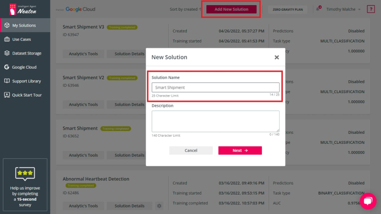
Give the name to your solution as "Smart Shipment" and description, after that click Next.
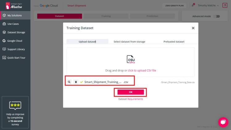
You will have to upload a training dataset that you have prepared.
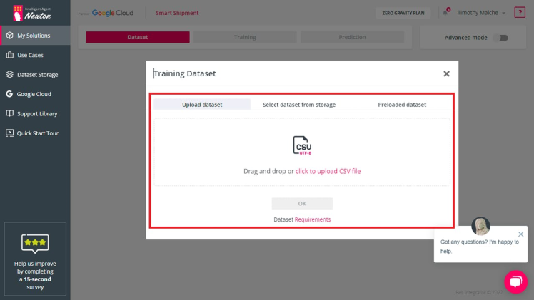
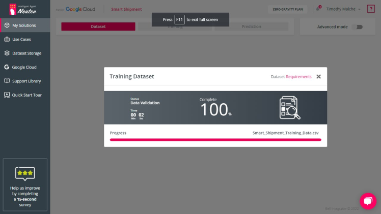
After the dataset is uploaded, click OK.
After that, select a target variable and click Next.
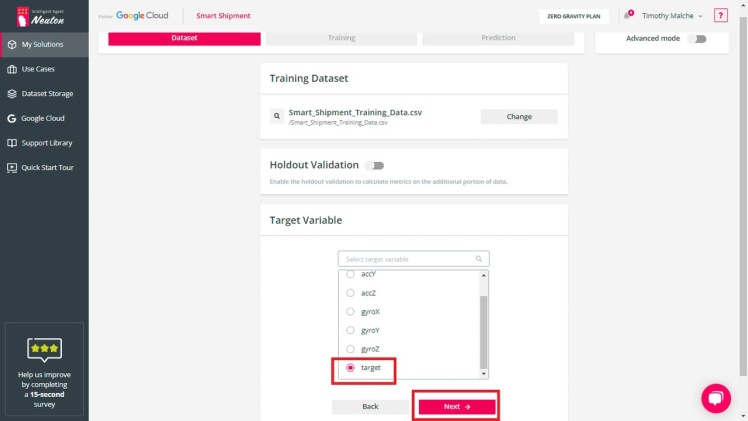
In the next screen, select task type "Multi Classification", metric "Accuracy", and enable "TinyML".
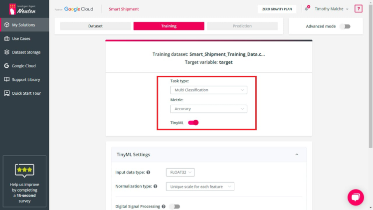
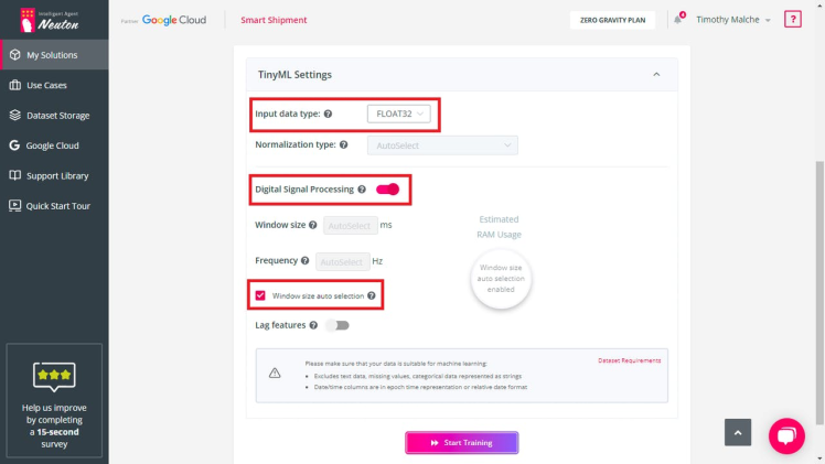
Scroll down to TinyML settings and select input data type as "FLOAT32", enable "Digital Signal Processing", select the checkbox "Window size auto selection", and then click the "Start Training" button.
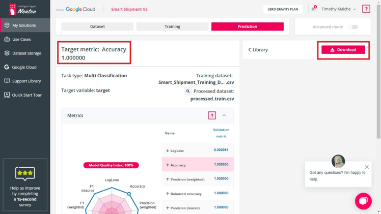
The training will be complete and you will see the Target Metric Accuracy. Now you can download the C Library that will be used to program the Smart Shipment Firmware.
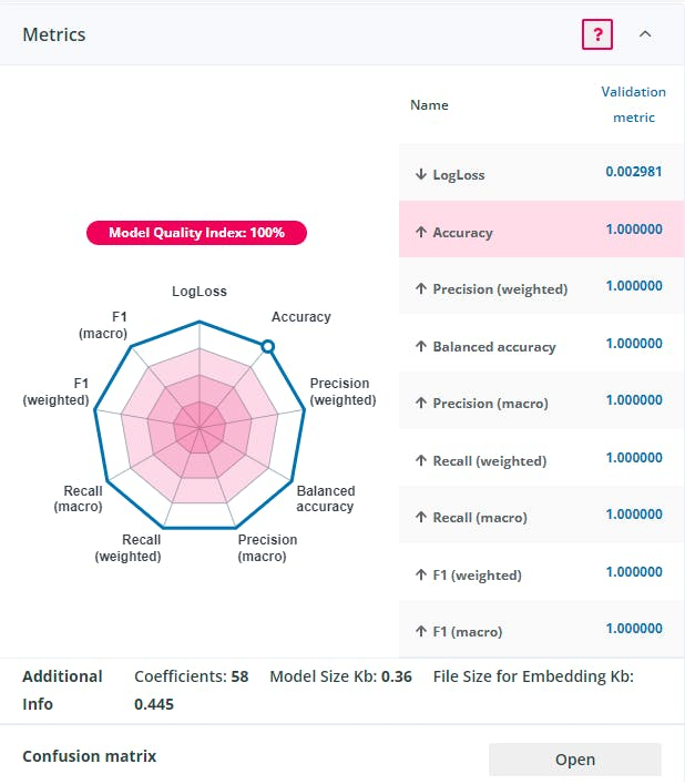
The embedding size of TinyML model developed using the neuton.ai is only 0, 445 kB. When I was trying to build the model for this project with Tensor Flow Lite I got model of 8, 95 kB. So with the same accuracy the model developed using the neuton.ai is 20 times smaller in size, that is critical when you embed the model to small MCU:
Model Footprint

Model Footprint
Step 3: Program Smart Shipment FirmwareCreate a root project directory for your Arduino "smart_shipment" project with the same name as your Arduino source file, create a subdirectory "src" and your smart_shipment.ino source file inside the root directory and extract and copy all the files that you have downloaded as "C source library" from neuton.ai inside the "src" subdirectory. Your directory structure must look like the following:
Arduino Project Directory Structure

Arduino Project Directory Structure
code for smart_shipment.ino
#include <M5Core2.h>
#include <string.h>
#include <PubSubClient.h>
#include <WiFi.h>
#include "src/neuton.h"

float accX = 0.0F;
float accY = 0.0F;
float accZ = 0.0F;

float gyroX = 0.0F;
float gyroY = 0.0F;
float gyroZ = 0.0F;

const char* ssid = "YOUR_WIFI_SSID";
const char* password = "YOUR_WIFI_PASSWORD";

//The broker and port are provided by http://www.mqtt−dashboard.com/
char *mqttServer = "broker.hivemq.com";
int mqttPort = 1883;

//Replace these 3 with the strings of your choice
const char* mqtt_client_name = "smart_shipment_1";
const char* mqtt_pub_topic = "status"; //The topic to which our client will publish


WiFiClient client;
PubSubClient mqttClient(client);

// the setup routine runs once when M5Stack starts up
void setup(){


  // Initialize the M5Stack object
  M5.begin();
  M5.IMU.Init();
  M5.Lcd.fillScreen(BLACK);
  M5.Lcd.setTextColor(GREEN , BLACK);
  M5.Lcd.setTextSize(2);

  Serial.begin(115200);
  WiFi.mode(WIFI_STA);                    //The WiFi is in station mode
  WiFi.begin(ssid, password);
  while (WiFi.status() != WL_CONNECTED) {
      delay(500);
      Serial.print(".");
   }
  Serial.println("");  Serial.print("WiFi connected to: "); Serial.println(ssid);  Serial.println("IP address: ");     Serial.println(WiFi.localIP());
  delay(2000);
  mqttClient.setServer(mqttServer, mqttPort);

}

void send_data(char status[]){
  if (!mqttClient.connected()){
      while (!mqttClient.connected()){
         if(mqttClient.connect(mqtt_client_name)){
            Serial.println("MQTT Connected!");
            //mqttClient.subscribe(mqtt_sub_topic);
         }
         else{
            Serial.print(".");
         }
      }
   }
   mqttClient.publish(mqtt_pub_topic, status);
   Serial.println("Message published");
   mqttClient.loop();
}

// the loop routine runs over and over again forever
void loop() {

  // put your main code here, to run repeatedly:
  M5.IMU.getGyroData(&gyroX,&gyroY,&gyroZ);
  M5.IMU.getAccelData(&accX,&accY,&accZ);

  float inputs[] = { accX, accY, accZ, gyroX, gyroY, gyroZ};

   if (neuton_model_set_inputs(inputs) == 0)
   {

      uint16_t predictedClass;
      float* probabilities;
      char pclass[50];
                if (neuton_model_run_inference(&predictedClass, &probabilities) == 0)
                {

                     if ((probabilities[predictedClass] > 0.6))
                    {
                      Serial.print(predictedClass);
                      if(predictedClass==0){
                        strcpy(pclass, "Stationary");
                      }
                      if(predictedClass==1){

                        strcpy(pclass, "Moving");
                      }
                      if(predictedClass==2){
                        M5.Lcd.fillScreen(BLACK);
                        strcpy(pclass, "Picked");
                      }

                      if(predictedClass==3){
                       M5.Lcd.fillScreen(BLACK);
                       strcpy(pclass, "Wrong");
                      }
                      if(predictedClass==4){
                      M5.Lcd.fillScreen(BLACK);
                      strcpy(pclass, "Thrown");
                      }
                      Serial.print("  probability: ");
                      Serial.print(probabilities[predictedClass] * 100.0, 0);
                      Serial.println('%');

                      M5.Lcd.setCursor(0, 20);
                      M5.Lcd.printf("Class: %s %d ", pclass, predictedClass);
                      M5.Lcd.setCursor(0, 65);
                      M5.Lcd.printf("Model Accuracy: %.2f", probabilities[predictedClass] * 100.0);
                      send_data(pclass);


                    }
                }
      }

   delay(20);
}The Smart Shipment Web App allows users to view the status of the shipment in a user-friendly way. The following is the code for Web App.
<html>
<head>
<script src="https://cdnjs.cloudflare.com/ajax/libs/paho-mqtt/1.0.1/mqttws31.min.js" type="text/javascript"></script>
<style>
body{
	margin-left:100px;
	margin-top:20px;
}
div.polaroid {
  width: 250px;
  box-shadow: 0 4px 8px 0 rgba(0, 0, 0, 0.2), 0 6px 20px 0 rgba(0, 0, 0, 0.19);
  text-align: center;
  background-color:#FFFFFF;
}

div.container {
  padding: 10px;
}
</style>
</head>
<body bgcolor="#363D45">

<h2 >Smart Shipment </h2>
<div >

  <img id="statusimg" src="img/loading.png" alt="AISpark" >

  <div >
  </div>
</div>


<script type="text/javascript">
// Create a client instance


client = new Paho.MQTT.Client("broker.hivemq.com", 8000 ,"smart_shipment_2");

// set callback handlers
client.onConnectionLost = onConnectionLost;
client.onMessageArrived = onMessageArrived;

// connect the client
client.connect({onSuccess:onConnect});


// called when the client connects
function onConnect() {
  // Once a connection has been made, make a subscription and send a message.
console.log("onConnect");
 client.subscribe("status");

}

// called when the client loses its connection
function onConnectionLost(responseObject) {
  if (responseObject.errorCode !== 0) {
    console.log("onConnectionLost:"+responseObject.errorMessage);
  }
}

  function doFail(e){
    console.log(e);
  }

// called when a message arrives
function onMessageArrived(message) {
  console.log("onMessageArrived:" + message.payloadString);
  document.getElementById("statusimg").src = "img/" + message.payloadString + ".png";
}

</script>
</body>
</html>
Web App displays the result as shown below.
Output on Web App

Output on Web App
SummaryThe project creation and execution are summarized in the following diagram.
Project Workflow

Project Workflow
It consists of the following two stages:
- Model Building
- Model Execution
The Model Building Stage has four steps
- Step 1: Collect the data using Data Collection Firmware and prepare the Training/Test Data.
- Step 2: Build the TinyML model from Training Data using Neuton TinyML Tool and download the TinyML model as C Source Library.
- Step 3: From the downloaded C Source Library, which is TinyML Model, program the Smart Shipment Firmware and embed it on the device.
- Step 4: Program the Web App using the PAHO MQTT Javascript library.
In the Model Execution stage, both the Smart Shipment Firmware (MQTT Client Publisher) and Web App (MQTT Client Subscriber) communicate with each other via the MQTT broker. The following is a detailed diagram that shows this communication process.
Project Communication Diagram

Project Communication Diagram
The Live Shipment Data is fed using the accelerometer and gyroscope to the MCU running the TinyML Model. After the inferencing is done, the data is published to the MQTT Broker on the topic "STATUS" by the MQTT Client Publisher running on MCU. The Publisher is connected to the Broker over a TCP port. The Web Application running MQTT Client Subscriber connects/subscribes to MQTT Broker over Websocket port at the same "STATUS" topic. As soon as data is published by the MQTT Publisher (MCU), it is received by the MQTT Subscriber (Web App).
Schematics, diagrams and documents
Code
Credits
timothy_malche
I am a researcher from India. My area of interest is IoT and AI. I love writing computer programs and experimenting. I also have passion to learn new things related to technology.
Related products


Leave your feedback...