
Smart Buildings Are Thrifty Buildings

Made by mbparks / Environmental Sensing / Fire & Pyrotechnics / Home Automation
About the project
Help you quickly prototype a custom Heating, ventilation, and air conditioning (HVAC) ductwork system.
Project info
Difficulty: Moderate
Platforms: Arduino
Estimated time: 1 week
License: GNU General Public License, version 3 or later (GPL3+)
Items used in this project
Hardware components


View all
Story
Project Overview
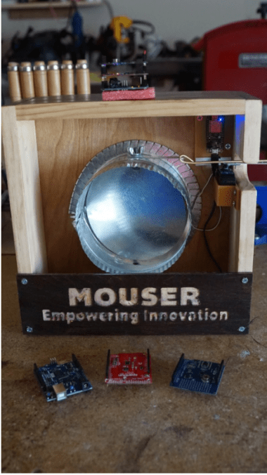
This project presents a two-part solution for a temperature control mechanism that will be automating an air duct damper, thus controlling the airflow into various rooms in a building. The first part is our weather sensor package that will monitor the environmental conditions in our spaces, including temperature, humidity, and atmospheric pressure (Figure 2).
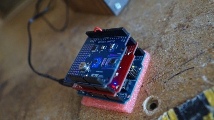
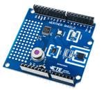
Figure 2: Board stack for sensor package. From bottom: Arduino, Wi-Fi Shield, TE Connectivity WeatherShield
The sensors communicate with our microcontroller over the I2C bus. Once the sensors have digitized and transmitted weather data to the microcontroller, we can perform additional work on the data. For example, we could convert temperature measurements from Celsius to Fahrenheit if so desired. Once we are satisfied with our data format, we can send it to a cloud-based IoT backend using the ESP8266 hardware and an HTTP-based RESTful API. Of note, the latest update to BACnet standard (BACnet Standard ASHRAE 135-2016) includes support for such RESTful HTTP-based web service interfaces.
At the heart of the weather sensor shield are the following five sensors:
- HTU2xD(F) (Temperature and Humidity)
- MS5637 (Temperature and Pressure)
- MS8607 (Temperature, Humidity and Pressure)
- TSYS01 (Temperature)
- TSD305 (Temperature and Contactless Temperature)
The second portion of the system is a control unit for the damper. It will contain a second wireless microcontroller platform, Adafruit’s Huzzah Feather, which is equipped with a servo motor and the appropriate mechanical linkages to the manual hardware of the damper (Figure 3).
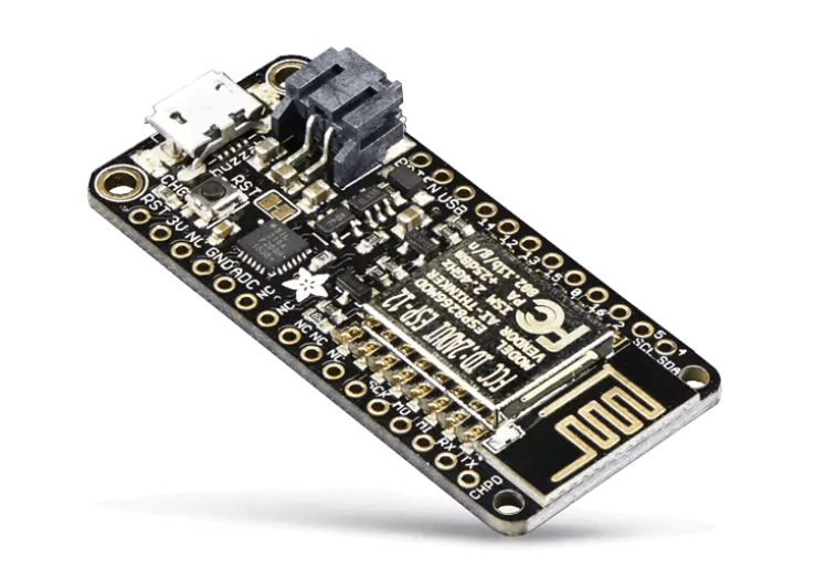
Figure 3: The Huzzah Feather receives weather data and makes informed decisions on controlling HVAC dampers
The Huzzah will reach up to the Ubidots server and request the necessary data, in this case temperature. The demonstration code shows a single set point temperature (74°F) for determining whether to open or close the damper. It might be desirable to include two different set points so that as the ambient temperature fluctuates above and below the set point temperature that the damper is not repeatedly opening and closing. For example, open the damper when the temperature reaches 78°F and close it when it reaches 72°F.
The Build
One problem that can sometimes arise from using pre-built breakout boards is that there can be I/O pin hardware conflicts. This just happens to be the case for this project. However, it is possible to cleverly hack a solution together so that we can get the prototype up and running. If this were to become a finished product, the engineering team would likely create a custom circuit board and design out the pin conflict.
For this particular project, both the WRL-13287 Wi-Fi Shield and the TE Connectivity Weather Shield have hardwired GPIO pin D9 for their own needs. For the Wi-Fi shield, pin 9 is being used as the TX pin for the software-based serial port that connects the development board to the ESP8266 SoC. On the weather shield, the same pin is part of a chip select multiplexer design along with pins 10 and 11.
Looking through the software for both shields, it was decided to alter the weather shield code. From a software perspective, the chip select multiplexer inputs were moved from pins 9, 10, and 11 to pins 10, 11, and 12. The code change occurred in the file titled TEWeatherShield.cpp which is a part of the TE Weather Shield library. Then, on the physical weather shield itself, the male header for pin 9 was removed and jumper wire was inserted to connect pin 12 to pin 9. In the end, while the Arduino would toggle pins 10, 11, and 12 to cycle through the various sensors, the weather shield itself saw no difference. Removing pin 9 ensured that there would be no conflict between the two shields both trying to drive pin 9. The only other impact to the final design was that this solution necessitated the board stack to follow the strict order of Arduino dev board, Wi-Fi shield, and then the weather shield sitting on top (Figure 4).
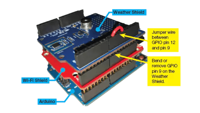
Figure 4: Note that pin 9 on the TE Connectivity WeatherShield must be removed and a jumper wire is placed between pin 9 and 12.
The Huzzah has an operating voltage of 3.3V, but when powered via USB, it is possible to tap into the USB’s 5V via the V_USB pin. This allows us to power the 5V servo motor without a separate supply. The Pulse Width Modulated (PWM) signal wire of the servo can remain at 3.3V.
In the provided GitHub repository, we provide both a schematic and board layout that breaks out the Huzzah pins and provides some male header pins for easily connecting the servo to the Huzzah. One thing to note is that the GPIO pins of the Huzzah are not sequentially numbered; they are clearly labeled on the board itself, so be certain you are wiring to the correct pins. For this project, GPIO pin 2 is using to provide the PWM control signal to the servo.
Lastly, if you intend to mount this design permanently, we have provided STL files for enclosures that can be 3D printed to keep the electronic hardware protected (Figure 5).
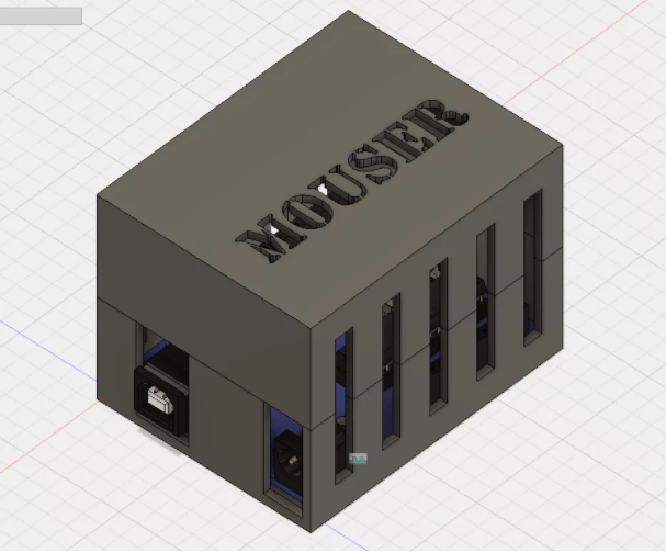
Figure 5: STL files for the 3D printable project enclosure is available in the project repository.
Software
The software for this project was developed using Microsoft’s Visual Studio Code, an extensible code editor that supports a variety of languages including C/C++ and the derivative wiring language used in the Arduino IDE (Figure 6). Visual Studio Code offers more robust development features such as code completion and breakpoints. However, this project can be accomplished just as easily in the standard Arduino Integrated Development Environment (IDE) if so desired.
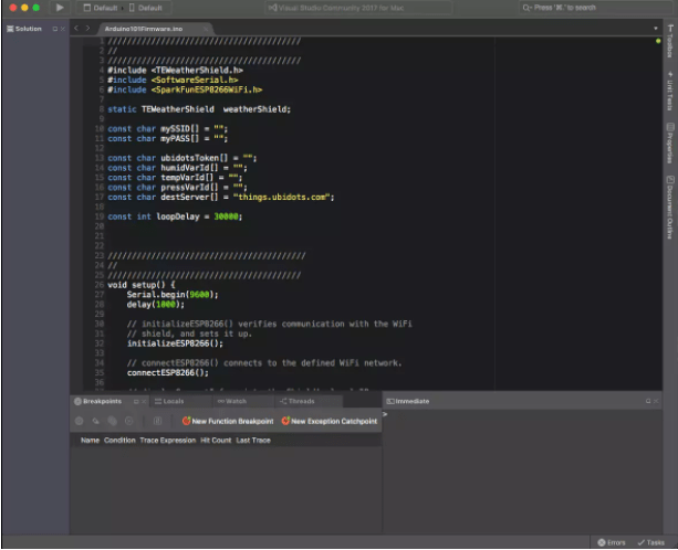
Figure 6: Visual Studio Code is a powerful code editor that adds professional programming features atop the standard Arduino IDE.
Libraries
First, we will grab the support libraries necessary to work with the chosen dev boards and shields. Thankfully, the hardware manufacturers for both the weather shield and the ESP8266 Wi-Fi shield provide the code on their respective GitHub repositories (Figure 7).
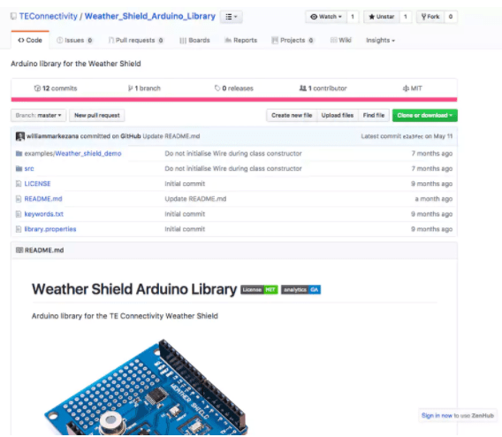
Figure 7: TE Connectivity provides all the needed software libraries on their GitHub repository.
The libraries we will be using include:
- TE Connectivity Weather Shield
- HTU2xD(F) (Temperature and Humidity)
- MS5637 (Temperature and Pressure)
- MS8607 (Temperature, Humidity and Pressure)
- TSYS01 (Temperature)
- TSD305 (Temperature and Contactless Temperature)
- ESP8266 Wi-Fi Shield
In addition to these libraries, we will also be using two standard libraries included as part of the Arduino IDE: SoftwareSerial.h and Servo.h.
Getting Some REST
RESTful APIs are an increasingly popular mechanism for allowing devices to communicate on the Internet, sans human involvement. For Web-based services, RESTful API is realized through HTTP methods such as POST, GET, PUSH, and DELETE.
In a nutshell, a RESTful API leverages what looks like a website address (URL) to exchange requests with a Web server. It is a simple yet elegant method to achieve autonomous communication between the Internet and the “Things” that comprise the IoT. Every Web service will provide their own API, but in general the format is fairly consistent. For this project, the Ubidots IoT backend service was selected (Figure 8). They have a well-documented API that is very easy to use. The documentation can be found here.
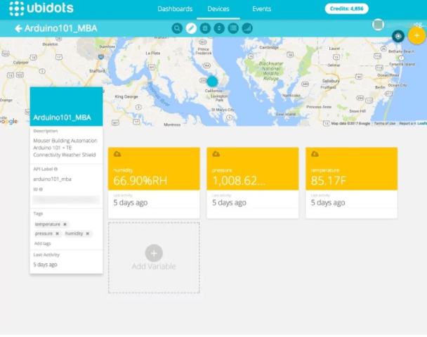
Figure 8: Ubidots provides for a simple yet powerful and inexpensive IoT backend.
In both devices, when uploading or downloading the sensor readings, the data itself is passed as a JSON message (JSON is short for JavaScript Object Notation), which is an open standard file format that has the benefit of being both efficient for digital transmission but also is humanly readable. For uploading the weather data to the Ubidots server, we use the POST method:
POST /api/v1.6/collections/values/?token=HTTP/1.1
Host: things.ubidots.com
Content-Type: application/json
Content-Length:
[{"variable": "TemperatureVariableID", "value":79.5}, {"variable": "PressureVariableID", "value":1010.2}, {"variable": "", "value":54.67}]
Where , , and would be replaced with a unique alphanumeric string for each variable that is generated by Ubidots for your particular account. will be replaced with a unique, account-based token from the Ubidots service. Think of the token as a random, very hard to guess account name. Lastly, must be calculated for each message. It is the number of characters, including the letters, numbers, spaces, and special characters.
There are software libraries to parse JSON messages or a custom lightweight function can be created that is application specific. For embedded developers that are accustomed to total control of their device, RESTful APIs present a paradigm shift in that the API provider can (and often will) update their API occasionally. This means the embedded system developer must respond with firmware updates to ensure the devices and IoT backend can continue to communicate.
To download the temperature data into the servo-connected Huzzah, we use GET:
GET /api/v1.6/devices//temperature/
values?page_size=1&token=XXX HTTP/1.1
Host: things.ubidots.com
Connection: close
In this example, would be replaced with the name you created for your device on the Ubidots website. Also, the part of the GET request that reads “?page_size=1” means that we are only interested in getting the most recent sensor readings. If it read “?page_size=5” then the server would return the data from the five most recent sensor readings.
Use
To simplify the mechanical aspects of this design, we are using a simple linkage that translates the move of the servo arm directly to the manual lever of the damper.
The sensor device can be placed anywhere in the room since it is a standalone device. This is helpful so that it can be placed away from air registers or windows that might inadvertently affect sensor readings for the purpose of regulating room temperature.
The Huzzah is powered with a standard micro-USB DC power supply—the same kind that power many of today’s smartphones and other portable electronics. The weather shield stack is powered with a 5V DC barrel jack power supply. Power supplies that provide sufficient power are included in the project shopping cart for your convenience.
Of course, this project could be altered to fit any number of scenarios or system configurations. For example, instead of opening and closing dampers, the system could be repurposed to open and close window blinds based on temperature. Or this could be done in addition to the damper control by simply adding a second control unit. The possibilities are endless.
Other Resources
Are you interested in building this project yourself or using it as a starting point for further development? If so, we have put together a few resources to help.
Credits
mbparks
Mike Parks is the owner of Green Shoe Garage, a custom electronics design studio and security research lab located in Southern Maryland. He produces content for the Gears of Resistance which shares news and tips for those interested in the maker movement, open-source hardware and software, STEAM education, citizen science, and digital citizenship. He is also an extra class ham radio operator, a licensed Professional Engineer in the state of Maryland, and most notably a dad.
Related products


Leave your feedback...