
Single Channel Lora Gateway Using Wio E5 Lora And Blynk

Made by vinayyn / Productivity / Sensors / Weather / IoT
About the project
Single channel LoRaWAN gateway using Seeed studio Wio-E5 Module, ESP8266, And Blynk.
Project info
Difficulty: Moderate
Platforms: Blynk, DFRobot, Seeed Studio, Silicon Labs
Estimated time: 1 day
License: GNU General Public License, version 3 or later (GPL3+)
Items used in this project
Hardware components

Software apps and online services
Story
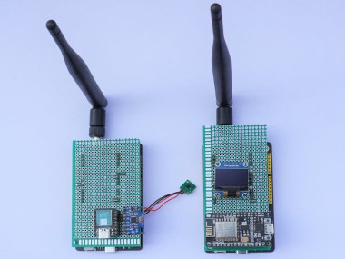
1 / 6 • Tranmitter and Receiver

Tranmitter and Receiver

Transmiiter Front Part

Receiver Front View

Transmitter Rear Part View

Receiver Rear view

Receiver OLED Display
In LoRa based system we can transmit the information to Another LoRa, then we can use that information and display it on the Local LCD Display or somewhere. if we need the data to be transmitted far longer distances than the LoRa Coverage? What do we have to do?
There are two methods available here
1. If any other networks(4G, 2G, 3G) are available in the particular area we can use LoRaWAN Gateways.
2. If there are no networks available, we can use the Another LoRa Module as Repeaters
The Above Two methods have their Respective Advantages and Disadvantages.
The LoRaWAN Gateways are Not pocket friendly and Requires Subscriptions to connect the devices and transfer data to the cloud.
The LoRa Repeaters Implementation Requires More Number Transceiver modules to Transfer the data to the Receivers. And it can’t store details on the cloud it can store the data locally.
In this Project, I am building Single channel LoRaWAN gateway using Seeed studio Wio-E5 Module, ESP8266, And Blynk.
Before briefly Explaining, Let's know a few basics about LoRaWAN.follow the link to learn more about What are LoRa® and LoRaWAN®?
LoRaWAN Gateways are one of four key components of the LoRaWAN network architecture:
1. End Nodes – Represents edge devices or sensors
2. Gateway – Collects or concentrates data from several end nodes
3. Network Server – Consolidates data from gateways for upload to the application server
4. Application Server – Processes or displays consolidated data
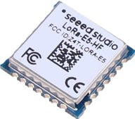
Let's know more about the Seeed studio Wio-E5 LoRa module.
Wio-E5 is a low-cost, ultra-low power, extremely compact, and high-performance LoRaWAN® Module designed by Seeed Technology Co., Ltd. It contains ST system-level package chip STM32WLE5JC, which is the world's first SoC integrated with the combo of LoRa® RF and MCU chip.
This module is also embedded with ARM Cortex M4 ultra-low-power MCU and LoRa® SX126X and therefore supports (G)FSK mode and LoRa®. 62.5kHz, 125kHz, 250kHz, and 500kHz bandwidth can be used in LoRa® mode, making it suitable for the design of various IoT nodes, supporting EU868 and US915.
This Wio E5 module is designed with industrial standards, hence it's highly suitable to be used in designing industrial IoT products, with a wide working temperature at -40℃ ~ 85℃.
Features- Ultra-low Power Consumption: as low as 2.1uA sleep current (WOR mode)
- Extremely Compacted Size: 12mm * 12mm * 2.5mm 28 pins SMT
- High Performance: TXOP=22dBm@868/915MHz; -136.5dBm sensitivity for SF12 with 125KHz BW
- Long Distance Use: 158dB link budget
- Wireless Connectivity: Embedded LoRaWAN® protocol, AT command, support global LoRaWAN® frequency plan
- Worldwide Compatibility: wide frequency range; EU868 / US915 / AU915 / AS923 / KR920 / IN865
- Great Flexibility: For users who want to develop software on the MCU of the module, other GPIOs of the MCU can be easily manipulated, including UART, I2C, ADC, etc. These rich GPIO interfaces are useful for users who need to expand peripherals.
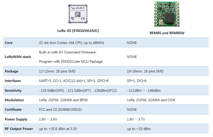
Simple Comparission Of LoRa E5 and RFM95
Here I am using Wio-E5 Factory AT Firmware to communicate with Host Microcontroller. Let's start learning with the AT Commands.
Wio-E5 series has a built-in AT command firmware, which supports LoRaWAN® Class A/B/C protocol and a wide frequency plan: EU868/US915/AU915/AS923/KR920/IN865. With this AT command firmware, developers can easily and quickly build their prototype or application.
The AT command firmware contains a bootloader for DFU and the AT application. The "PB13/SPI_SCK/BOOT" pin is used to control Wio-E5 to stay in the bootloader or jump to the AT application. When PB13 is HIGH, the module will jump to AT application after reset, with a default baud rate of 9600. When PB13 is LOW (press the "Boot" button on Wio-E5 mini/ Wio-E5 Development Kit), the module will stay in the bootloader, and keep transmitting a "C" character every 1S at baud rate 115200.
AT Commands
All command lines must start with "AT" and end with a carriage return character. We will use <CR> to represent a carriage return character.
- The command is case insensitive
- All commands have a response
- Command length never exceeds a total of 528 characters
- One valid AT Command must end with 'n', "rn" is also valid
- If the command timeout feature is enabled, end 'n' will not be mandatory
- means the newline character. means carriage return
- UART2 configuration "9600, 8, n 1" (8 bits data, no parity, 1 stop bit);
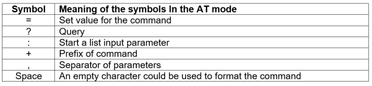
AT Commands Symbols
AT Commands Format
All commands in this document end with<CR><LF>. To facilitate the description, all is intentionally omitted in this document. <CR> and <LF> represent a carriage return character and a linefeed character respectively.
Query Commands
query command to check LoRaWAN modem configuration, such as channel configuration, ADR status, TX power, etc.
Example: AT+MODE=? //Querying the mode of work
Configure / Control
configures/control command to set new configuration or control transaction.
RETURN Data
Return data is in the format like "+CMD: RETURN DATA"
Example +MODE: TEST
AT Commands

Error Codes
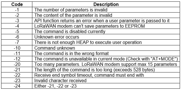
Example: The number of parameters is invalid
AT+mode=1
+MODE: ERROR(-1)
In the above example, we are getting an Error number of -1, which means we are setting the invalid command.
How to resolve the error: in the at command, it is mentioned when the prefix command is entered respective value need to enter. In the above example, we have to select work mode, based on the work mode command we can only three values LWABP, LWOTAA, and TEST. But the entered value is 1, which means it is not a valid value
Let's enter the Correct value and what will be the Return Data
AT+mode=TEST
+MODE: TEST
AT+mode=LWABP
+MODE: LWABP
AT+mode=LWOTAA
+MODE: LWOTAA
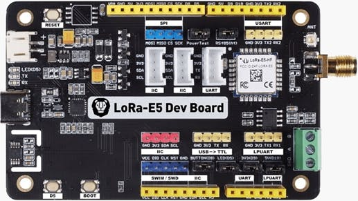
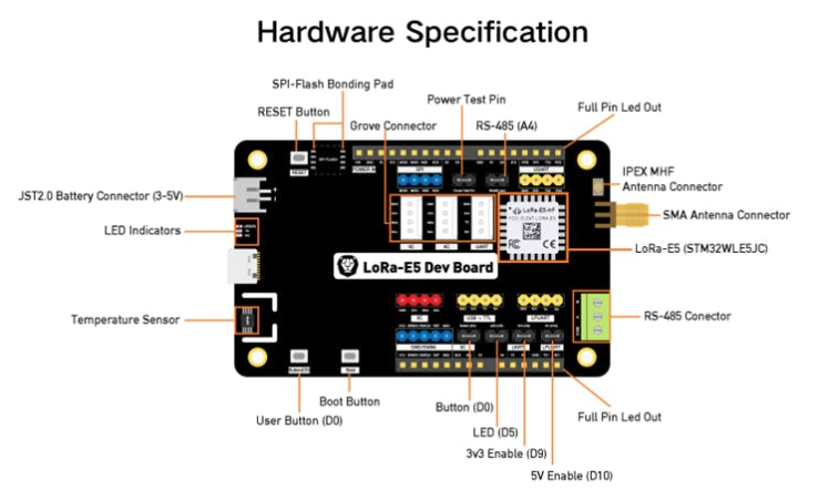
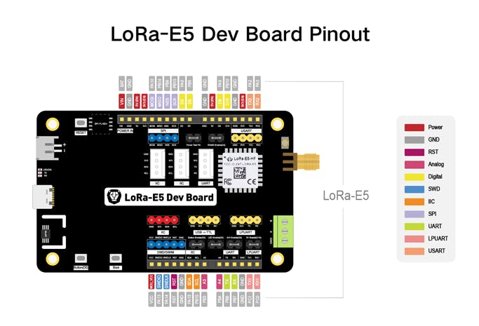
For creating this project I am using Two Wio-E5 Development KitWio E5 Development kit is based on STM32WLE5JC.
Wio-E5 Dev Board has a long-distance transmission range of Wio-E5 up to 10km in an open area. The sleep current of Wio-E5 modules on board is as low as 2.1 uA(WOR mode). It is designed with industrial standards with a wide working temperature at -40 ℃ ~ 85℃, high sensitivity between -116.5 dBm ~ -136 dBm, and power output up to +20.8dBm at 3.3V.
Wio-E5 Dev Board also has rich interfaces. Developed to unlock the full functionality of the Wio-E5 module, Wio-E5 Dev Board has led out the full 28 pins of Wio-E5 and provides rich interfaces including Grove connectors, RS-485 terminal, male/female pin headers for you to connect sensors and modules with different connectors and data protocols, saving your time on wire soldering. You could also easily power the board by connecting the battery holder with 2 AA batteries, enabling temporary use when lacking an external power source. It is a user-friendly board for easy testing and rapid prototyping.
Since Wio-E5 is a LoRaWAN® chip with an MCU, there are three main ways to utilize the Wio-E5 Dev Board:
1: Connect Wio-E5 Dev Board to PC via USB and control by AT commands
There is a built-in USB to UART function on board, you could just simply connect the Wio-E5 Dev Board to your PC with a USB type C cable, and use serial communication software to send AT commands and read data from the board
2: Connect Wio-E5 Dev Board to another mainboard via UART and control by AT commands
For example, connect Wio-E5 Dev Board to Seeeduino XIAO and the Expansion Board via UART, send AT commands, and read data from Seeeduino XIAO through Arduino IDE serial monitor.
3: Develop user applications by using SDK
Develop your LoRa® development board with MCU function by using STM32Cube Programmer, which is the SDK officially provided by STMicroelectronics. To download this SDK resource, please find the resources in learning and document down below.
With all the outstanding features listed above, the Wio-E5 Dev Board will be a superior choice for IoT device development, testing, prototyping, and applications in long-distance, ultra-low power consumption IoT scenarios like smart agriculture, smart office, and smart industry.
In this project, I will explain only The AT Command which is utilized. For a detailed AT Commands description follow this link
Communicating The LoRa Modules using AT Commands
- We need two LoRa Module Here to test the basic AT commands require to complete the project.
- These two modules are connected to the Computer using a Type C USB connector.
- To send and receive the data we require serial terminal software on the PC.
- One LoRa Module Is Used as a Transmitter and Another LoRa Module Is used as a receiver to test the AT Commands
Transmitter Side
1. Enter TEST mode:
TEST command is not like other commands, it is a serious command, and includes several sub-commands, refer to the table below. With test mode, the user could do an RF performance test quickly without any knowledge of the LoRa chip. Commands which are related to RF configuration are disabled in test mode.
LWABP7, LWOTAA8, and TEST are supported. LoRaWAN modem can only work with one mode at a time. By default, LWABP is enabled, all test commands are unavailable, and LoRaWAN will return an error(-12) if it receives the test command in non-test mode.
The "AT+MODE" command will reset the LoRaWAN stack when first entering LWABP/LWOTTA mode and reset the LoRa chip when first entering test mode.
LWABP/LWOTAA mode status is remembered by the LoRaWAN modem, each time the LoRaWAN modem starts, it will enter the previous working mode before resetting or repower.
Here to test the modules I will select the Test Mode
AT+MODE=TEST
+MODE: TEST ← once the work mode is successfully configured the return data will indicate the mode we selected.
←LoRaWAN Modem Enter Test mode successfully
Test Sub-Command
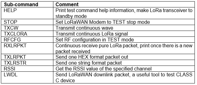
2.Set RF Configuration: RFCFG supports set frequency, SF, bandwidth, TX preamble, RX preamble, and TX power settings.
TX and RX share all configurations except "preamble length", the user could choose a different preamble length. For LoRa communication, it is strongly recommended to set RX preamble length longer than TX's. Bandwidth only supports 125KHz / 250KHz / 500KHz.
Depending on Semtech SX1276 (PA_BOOST/RFO) and the design solution of the module, the MAX output power of different band LoRaWAN modems could be different.
The syntax for RF Configuration
AT+TEST=RFCFG, [FREQUENCY], [SF], [BANDWIDTH], [TX PR], [RX PR], [TX POWER], [CRC], [IQ], [NET]
Where,
SF: Spreading Factor
TX PR: TX Preamble
RX PR: RX Preamble
IQ: Inverted IQ
NET: Choosing Public Or Private Network
EX: AT+TEST=RFCFG, 866, SF12, 125, 12, 15, 14, ON, OFF, OFF
+TEST: RFCFG F:866000000, SF12, BW125K, TXPR:12, RXPR:15, POW:14dBm, CRC: ON, IQ: OFF, NET: OFF
FREQUENCY: 866MHz
SpreadFactor: SF12
Bandwidth: 125KHz
TX Preamble: 12
RX Preamble: 15
Power: 14dBm
3. TX LoRa Packet: After entering test mode, the user could send the LoRa packet through the "AT+TEST=TXLRPKT" sub-command. The command format is like the below:
AT+TEST=TXLRPKT, "AB"
+TEST: TXLRPKT "AB"
+TEST: TX DONE ← when the data is sent successfully it will acknowledge
as Done
Command sequence to send LoRa packet:
AT+MODE=TEST /// Set test mode
AT+TEST=? //// Query test mode, check RF configuration
AT+TEST=RFCFG, [FREQUENCY], [SF], [BANDWIDTH], [TXPR], [RXPR], [POW], [CRC], [IQ], [NET]// / Set RF Configuration
AT+TEST=TXLRPKT, "HEX String"// Send HEX format packet
Receiver side
On the receiver side, the few basic configuration commands are the same as the transmitter, I will Again List those here.
1. Enter TEST mode
2. Set RF Configuration
3. RX LoRa Packet: After entering test mode, the user could enter LoRa packet continuous RX mode through the RXLRPKT subcommand (AT+TEST=RXLRPK). Like below:
AT+TEST=RXLRPKT
+TEST: RXLRPKT
Command sequence to receive LoRa packet:
AT+MODE=TEST // Set test mode
AT+TEST=?// Query test mode, check RF configuration
AT+TEST=RFCFG, 866, SF12, 125, 12, 15, 14, ON, OFF, OFF//Set RF Configuration
AT+TEST=RXLRPKT // Enter RX continuous mode.
LoRa Transmitter and Receiver AT Commands Testing
Now I will give details of the main project, in the transmitter part I am using XIAO SAMD21 Microcontroller, Wio E5 LoRa Dev Kit, SI7051 temperature sensor, and MPU 6050 Accelerometer gyroscope sensors, along with the 2X AA Battery. in the receiver part I am using Wio E5 LoRa Dev Kit, ESP8266 NodeMCU, OLED Display.
The transmitter part collects the temperature details, accelerometer, and gyroscope sensor collects the various movements of the device. if there is a change in the Position of the transmitter, the microcontroller transfers the alert data to the receiver using LoRa along with the surrounding temperature details. The transmitter Part is powered by two AA Size batteries that can run the transmitter for up to a couple of months.
Transmitter Block Diagram

Transmitter Block Diagram
Transmitter section connection diagram

Transmitter section connection diagram
In the receiver part The LoRa receives the data and the microcontroller processes the data and then displays the data in OLED Display. in Parallel transfers the details to the Blynk cloud servers using Wi-Fi to display them in the android app. The android app will display the Temperature, position of the Transmitter, RSSI, and Status of the Transmitter and Receiver connection.
Receiver Block diagram

Receiver Block diagram
Receiver Connection Diagram

Receiver Connection Diagram
Project Demo Video
Schematics, diagrams and documents
Code
Credits
Related products


Leave your feedback...