
Simple Ssd1306 I2c Oled Analog Display With Visuino

About the project
Connect OLED Display to Arduino, and print analog values on it - Quick and Easy!
Project info
Difficulty: Easy
Estimated time: 1 hour
License: GNU General Public License, version 3 or later (GPL3+)
Items used in this project
Hardware components

Software apps and online services
Story
OLED Displays are some of the coolest and most advanced modules that you can use in your Arduino project. They come in small form factor and have very low power consumption while delivering bright vivid colors. Some of the cheapest and commonly available are the SSD1306 I2C and SPI OLED Modules. The I2C version needs only 2 control wires, and this makes it perfect for Arduino projects leaving plenty of other pins available for other peripherals.
In this tutorial, I will show you how easy it is to connect I2C SSD1306 OLED Display to Arduino, and program it with Visuino to display the values from an Analog pin.
Step 1: Components
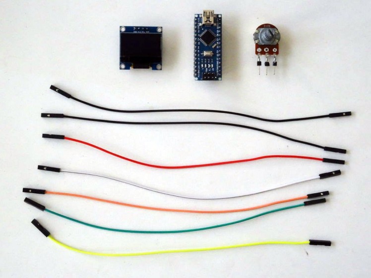
- One Arduino compatible board (I use Arduino Nano, because I have one, but any other will be just fine)
- One 10K Potentiometer (You can use any other Analog sensor instead of the Potentiometer)
- 7 Female-Female jumper wires
1 / 3 • Picture 1

Picture 1

Picture 2

Picture 3
- Connect Female-Female wires - Power (red), Ground (black), SDA (green), and SCL (yellow) to the I2C SSD1306 OLED Display (Picture 1)
- Connect the other end of the Ground (black) to the Ground pin of the Arduino board (Picture 2)
- Connect the other end of the Power (red) to the 5V Power pin of the Arduino board (Picture 2)
- Connect the other end of the SDA wire (green) to SDA/Analog pin 4 of the Arduino Nano board (Picture 2)
- Connect the other end of the SCL wire (yellow) to SCL/Analog pin 5 of the Arduino Nano board (Picture 2)
- Picture 3 shows where are the Ground, 5V Power, SDA/Analog pin 4, and SCL/Analog pin 5 pins of the Arduino Nano
1 / 4 • Picture 1

Picture 1

Picture 2

Picture 3

Picture 4
- Connect a Female-Female Power wire (orange) to the one end pin of the Potentiometer (Picture 1)
- Connect a Female-Female Signal wire (white) to the Wiper (center) pin of the Potentiometer (Picture 1)
- Connect a Female-Female Ground wire (black) to the other end pin of the Potentiometer (Picture 1)
- Connect the other end of the Power wire (orange) to the REF Analog Reference pin of the Arduino board (Picture 2)
- Connect the other end of the Signal wire (white) to the Analog pin 0 of the Arduino board (Picture 2)
- Connect the other end of the Ground wire (black) to the Ground pin of the Arduino board (Picture 3)
- Picture 4 shows in Red the Arduino Nano pins that were connected in this step. The picture also shows the pins connected in Step 2 in Blue
1 / 2 • Picture 1

Picture 1

Picture 2
To start programming the Arduino, you will need to have the Arduino IDE installed from here: http://www.arduino.cc/.
Please be aware that there are some critical bugs in Arduino IDE 1.6.6.
Make sure that you install 1.6.7 or higher, otherwise this Tutorial will not work!
The Visuino: https://www.visuino.com also needs to be installed.
- Start Visuino as shown in the first picture
- Click on the "Tools" button on the Arduino component (Picture 1) in Visuino
- When the dialog appears, select "Arduino Nano" as shown in Picture 2
1 / 4 • Picture 1

Picture 1

Picture 2

Picture 3

Picture 4
We need to add component to control the OLED Display:
- Type "oled" in the Filter box of the Component Toolbox, then select the "SSD1306 OLED Display (I2C)" component (Picture 1) and drop it in the design area (Picture 2)
- In the Object Inspector, you may need to change the value of the "Address" property of the DisplaySSD13061 component (Picture 2) (See this tutorial to learn how you can scan the I2C bus to find the I2C Address of the Display)
- Connect the "Out" pin of the DisplaySSD13061 component to the "In" pin of the "I2C" channel of the Arduino component (Picture 2)
- Connect the "In" Input pin of the DisplaySSD13061 (Picture 3) to the "Out" output pin of the "Digital[ 14 ]/Avalog[ 0 ]" channel of the Arduino component (Picture 4)
1 / 2 • Picture 1

Picture 1

Picture 2
- In Visuino, press F9 or click on the button shown on Picture 1 to generate the Arduino code, and open the Arduino IDE
- In the Arduino IDE, click on the Upload button to compile and upload the code (Picture 2)
1 / 3 • Picture 1

Picture 1

Picture 2

Picture 3
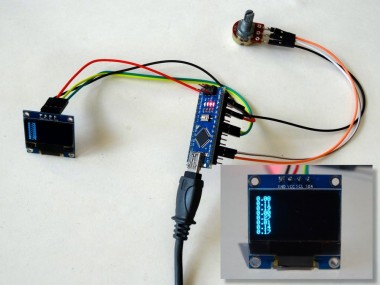
Congratulations! You have completed the project.
Picture 1 and the Video show the connected and powered up project. The Analog value of the Analog Pin 0 will start printing on the OLED Display as seen on the Video and Picture 2. If you turn the Potentiometer, the values will change.
On Picture 3 you can see the complete Visuino diagram. Also attached is the Visuino project, that I created for this Tutorial. You can download and open it in Visuino: https://www.visuino.com
Credits
Related products


Leave your feedback...