

Send And Receive Text Messages (sms) With Gsm Sim900 Shield

Made by Ron / Communication / IoT
About the project
Send and Receive Text Messages (SMS) with GSM SIM900 Shield from Seeed Studio - Quick and Easy!
Project info
Difficulty: Easy
Estimated time: 1 hour
License: GNU General Public License, version 3 or later (GPL3+)
Items used in this project

Software apps and online services
Story
One of the essential elements of building IoT project is the ability to connect devices. Wi-Fi and Bluetooth are good low cost choices, but they work only at close ranges, or in hotspot areas. When the device needs to be at a remote location GSM is a good and easy to setup option.
In this Tutorial, I will show you how easy it is to send and receive SMS messages over GSM with Arduino.
In the following Tutorials, I will also show you how you can connect over GSM to Internet and access servers, and how you can handle voice calls.
Step 1: Components
1 / 2 • Picture 1

Picture 1

Picture 2
- One Arduino Mega (You can use other boards, but it is best to use a board that has 2 or more serial ports. The project can be modified to use Software Serial, but using a hardware serial is recommended)
- One SIM900 based GSM Shield or compatible Shield or Module with installed SIM Card (Picture 2) (I used a Version 1.0 GSM/GPRS Shield from Seeed Studio)
- 2 Female-Male jumper wires
1 / 5 • Picture 1

Picture 1

Picture 2

Picture 3

Picture 4

Picture 5
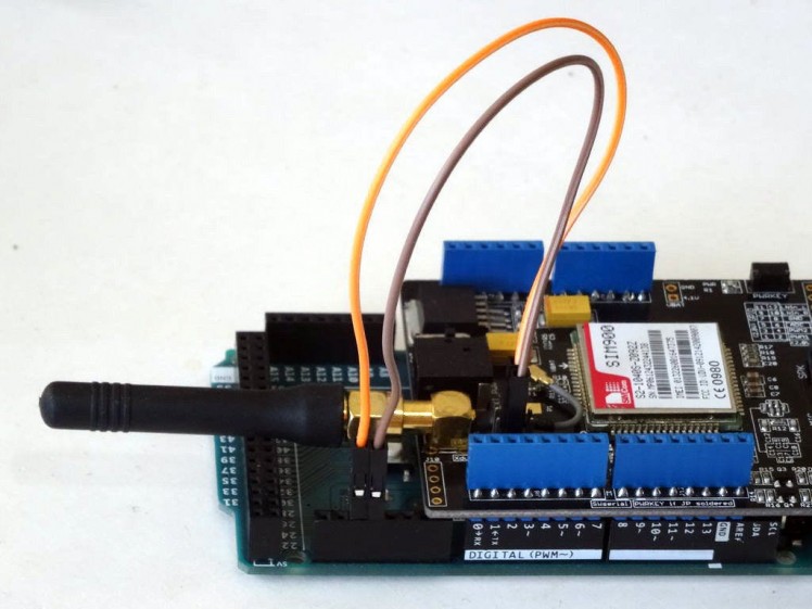
- Remove the jumper Caps from the GSM Shield's RX and TX Selection Jumpers (Picture 1)
- Plug the GSM Shield on the top of the Arduino Mega
- Connect the Male End of a Male-Female jumper wire (Orange wire) to the RX1 Pin of the Arduino Mega (Pictures 2 and 3)
- Connect the Male End of a Male-Female jumper wire (Brown wire) to the TX1 Pin of the Arduino Mega (Pictures 2 and 3)
- Connect the Female end of the RX1 wire (Orange wire) to the center pin of the RX Selection Jumper of the GSM Shield (Picture 4)
- Connect the Female end of the TX1 wire (Brown wire) to the center pin of the TX Selection Jumper of the GSM Shield (Picture 4)
- Picture 5 shows the installed and connected GSM Shield
1 / 2 • Picture 1

Picture 1

Picture 2
To start programming the Arduino, you will need to have the Arduino IDE installed from here: http://www.arduino.cc/ .
Make sure that you install 1.6.7 higher, otherwise this Tutorial will not work!
The Visuino: https://www.visuino.com also needs to be installed.
- Start Visuino as shown in the first picture
- Click on the "Tools" button on the Arduino component (Picture 1) in Visuino
- When the dialog appears, select "Arduino Mega 2560" as shown in Picture 2
1 / 3 • Picture 1

Picture 1

Picture 2

Picture 3
The GSM Shield is configured by default for 19200 serial port speed. We need to configure Serial Port 1 for this speed:
- In the Object Inspector, expand the "Serial" property, then the "Item[ 1 ]" Sub-Property, and select its "Speed" Sub-Property (Picture 1)
- In the Object Inspector, click on the "Down Arrow" button next to the value of the "Speed" Sub-Property (Picture 1)
- From the Drop Down list select the "19200" (Picture 2), to change the property value (Picture 3)
1 / 4 • Picture 1

Picture 1

Picture 2

Picture 3

Picture 4
We need to add component to control the GSM Module. The Module is controlled through the Serial channel, so we need to connect it. Digital Pin 9 is used to power On/Off the Module:
- Type "gsm" in the Filter box of the Component Toolbox, then select the "GSM/GPRS Serial" component (Picture 1), and drop it in the design area (Picture 2)
- Connect the "Out" output pin of the GSM1 component to the "In" input pin of the "Serial[ 1 ]" channel of the Arduino component (Picture 2)
- Connect the "Power" output pin of the GSM1 component to the "Digital" input pin of the "Digital[ 9 ]" channel of the Arduino component (Picture 3). This pin will turn On/Off the power of the GSM Module
1 / 4 • Picture 1

Picture 1

Picture 2

Picture 3

Picture 4
It takes some time for the GMS Module to initialize. It is nice if we have some indication that the module is ready. For this we will send "GSM Ready" text to the Serial port when the module is ready:
- Type "text val" in the Filter box of the Component Toolbox, then select the "Text Value" component (Picture 1), and drop it in the design area (Picture 2)
- In the Object Inspector set the value of the "Value" property to "GSM Ready" (Picture 2)
- Connect the "Ready" output pin of the GSM1 component to the "In" input pin of the TextValue1 component (Picture 3)
- Connect the "Out" output pin of the TextValue1 component to the "In" input pin of the "Serial[ 0 ]" channel of the Arduino component (Picture 4)
1 / 4 • Picture 1

Picture 1

Picture 2

Picture 3

Picture 4
The GSM component consists of many modules performing different tasks. Since we will use only SMS we need to add only "Short Message" module, and then add one "Send SMS" function to it:
- In the Design Area, select the GSM1 component (Picture 1)
- In the Object Inspector, click on the "..." button next to the value of the "Module" property of the GSM1 component (Picture 1)
- In the Modules editor select “Short Message”, and then click on the "" button (Picture 2) to add one (Picture 3)
- In the Object Inspector, click on the "..." button next to the value of the "Functions" property of the "Short Message" module (Picture 3)
- In the Functions editor select “Send SMS”, and then click on the "" button (Picture 2) to add one
1 / 4 • Picture 1

Picture 1

Picture 2

Picture 3

Picture 4
- In the Object Inspector, set the value of the "Address" property of the "Send SMS" element to the phone number where you want to send the message (In my case, to test I entered the number of my SIM card so the module will receive and print the messages that it sends) (Picture 1 - shows a made up number)
- In the Object Inspector, select the "Text" property (Picture 2)
- Click on the "Pin" button at front of the "Text" property (Picture 2)
- From the Drop Down list, select the "String SinkPin" (Picture 3). This will add new "Text" pin to the "Send SMS" function (Picture 4)
- Close the Element editor dialogs (Picture 4)
- Connect the "Out" output pin of the "MessageInfo" block of the GSM1 component to the "In" input pin of the "Serial[ 0 ]" channel of the Arduino component (Picture 4)
1 / 3 • Picture 1

Picture 1

Picture 2

Picture 3
The Serial port receives one character at a time. To send an SMS messages, we need to get all the characters from a line, create a Text out of it, and send it to the GSM Module:
- Type "char" in the Filter box of the Component Toolbox, then select the "Char to Text" component (Picture 1), and drop it in the design area (Picture 2)
- Connect the "Out" output pin of the "Serial[ 0 ]" channel of the Arduino component to the "In" input pin of the CharToText1 component (Picture 2)
- Connect the "Out" output pin of the CharToText1 component to the "Text" input pin of the "Send SMS" element of the GSM1 component (Picture 3)
1 / 4 • Picture 1

Picture 1

Picture 2

Picture 3

Picture 4
We need to make sure that we send the SMS after the text has been properly updated. We can use a Delay component with short delay for that:
- Type "delay" in the Filter box of the Component Toolbox, then select the "Delay" component (Picture 1), and drop it in the design area (Picture 2)
- In the Object Inspector, set the value of the "Interval" property to "100" (Picture 2)
- Connect the "Out" output pin of the CharToText1 component to the "In" input pin of the Delay1 component (Picture 3)
- Connect the "Out" output pin of the Delay1 component to the "Clock" input pin of the "Send SMS" element of the GSM1 component (Picture 4)
1 / 2 • Picture 1

Picture 1

Picture 2
- In Visuino, Press F9 or click on the button shown on Picture 1 to generate the Arduino code, and open the Arduino IDE
- In the Arduino IDE, click on the Upload button, to compile and upload the code (Picture 2)
1 / 5 • Picture 1

Picture 1

Picture 2

Picture 3

Picture 4

Picture 5
Congratulations! You have completed the project.
Picture 1 shows the connected and powered up project. On Picture 2 you can see the complete Visuino diagram. If you connect with Serial Terminal to the Arduino, after about 30 seconds you will see the "GSM Ready" message appear (Picture 3)
Once the message appears, if you Type some text, and click "Send" (Picture 4), the text will be sent as SMS message. If you have selected as phone number on Step 8 to the phone of the SIM card on the Shield, after a while you will receive the message, and it will be shown on the Serial Terminal (Picture 5). If you have set the number of a different device on Step 8, the messages will be sent to that device.
You can send SMS messages to the phone number from other phones and devices, and they also will be shown in the serial terminal.
Also attached is the Visuino project, that I created for this Tutorial. You can download and open it in Visuino: https://www.visuino.com
Credits
Related products


Leave your feedback...