
Scan The Arduino I2c Bus For Connected I2c Devices

Made by Ron / Displays / Home Automation / Sensors
About the project
Discover the addresses of the I2C devices connected to Arduino with Visuino - Quick and Easy!
Project info
Difficulty: Easy
Estimated time: 1 hour
License: GNU General Public License, version 3 or later (GPL3+)
Items used in this project

Software apps and online services
Story
I2C Devices and modules are widely available, and very popular in Arduino projects. Each I2C device has an Address usually fixed or configurable by jumpers. When working with the I2C device, the first task is discovering what is the device's address. You can usually find it from documentation or specifications, but sometimes this can be tedious or simply not available. It is easy however to scan the Arduino I2C bus and discover the addresses of the connected devices.
In this Tutorial I will show you how easy and quick it is to scan the I2C bus and discover the addresses of the connected I2C devices with the help of Visuino - an easy to use graphical development environment for Arduino.
Step 1: Components
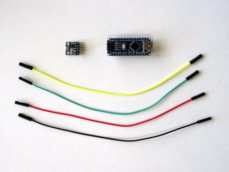
- One Arduino compatible board (I use Arduino Nano, because I have one, but any other will be just fine)
- One I2C Module (I used BMP180 Sensor Module because I have one but any other I2C Module will work)
- 4 Female-Female jumper wires
1 / 3 • Picture 1

Picture 1

Picture 2

Picture 3
- Connect 5V VCC Power (Red wire), Ground (Black wire), SDA (Green wire), and SCL (Yellow wire), to the I2C Module (Picture 1)
- Connect the other end of the Ground wire (Black wire) to Ground pin of the Arduino board (Picture 2)
- Connect the other end of the 5V VCC Power wire (Red wire) to the 5V power pin of the Arduino board (Picture 2)
- Connect the other end of the SDA wire (Green wire) to SDA/Analog pin 4 of the Arduino Nano board (Picture 2)
- Connect the other end of the SCL wire (Yellow wire) to SCL/Analog pin 5 of the Arduino Nano board (Picture 2)
- Picture 3 shows where are the Ground, 5V Power, SDA/Analog pin 4, and SCL/Analog pin 5, pins of the Arduino Nano
1 / 2 • Picture 1

Picture 1

Picture 2
To start programming the Arduino, you will need to have the Arduino IDE installed from here: http://www.arduino.cc/.
Please be aware that there are some critical bugs in Arduino IDE 1.6.6.
Make sure that you install 1.6.7 or higher, otherwise this Tutorial will not work!
The Visuino: https://www.visuino.com also needs to be installed.
- Start Visuino as shown in the first picture
- Click on the "Tools" button on the Arduino component (Picture 1) in Visuino
- When the dialog appears, select Arduino Nano as shown in Picture 2
1 / 3 • Picture 1

Picture 1

Picture 2

Picture 3
To scan the I2C bus, we need to add "I2C Scan" element to the Arduino I2C:
- In the design area, select the Arduino component (Picture 1)
- In the Object Inspector, expand the "I2C" property, then click on the "..." button next to the value of the "Elements" sub-property (Picture 1)
- In the Elements editor, select "I2C Scan" in the right view then click on the "" button on the left(Picture 2) to add I2C Scan element (Picture 3)
- Close the Elements editor
1 / 3 • Picture 1

Picture 1

Picture 2

Picture 3
We want to perform a scan as soon as the Arduino code starts executing. For this we can use the "Start" component. It generates a clock event when the Arduino code starts executing:
- Type "start" in the Filter box of the Component Toolbox then select the "Start" component (Picture 1), and drop it in the design area
- Connect the "Out" pin of the Start1 component to the to the "Scan" input pin of the "I2C Scan1" Element of the "I2C.Elements" of the Arduino component (Picture 2)
- Connect the "Address" output pin of the "I2C Scan1" Element of the "I2C.Elements" of the Arduino component, to the "In" input pin of the "Serial[ 0 ]" channel of the Arduino component (Picture 3)
1 / 2 • Picture 1

Picture 1

Picture 2
- In Visuino, Press F9 or click on the button shown on Picture 1 to generate the Arduino code, and open the Arduino IDE
- In the Arduino IDE, click on the Upload button, to compile and upload the code (Picture 2)
1 / 3 • Picture 1

Picture 1

Picture 2

Picture 3
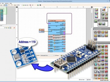
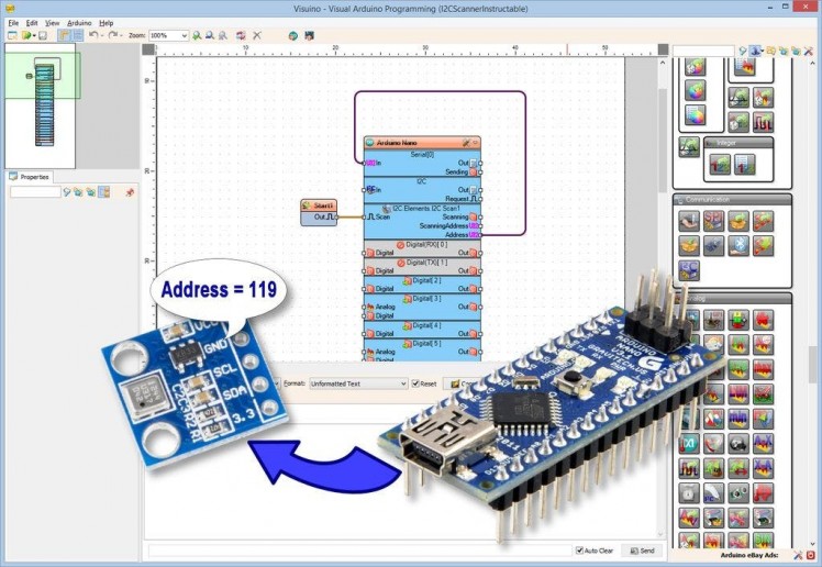
You can see the connected and running project on Picture 1.
If you open Serial Terminal in the Arduino IDE or Visuino, you will see the I2C address of the Module (Picture 2)
On Picture 3 you can see the complete Visuino diagram.
Congratulations! You have learned how to scan the ArduinoI2C bus for devices with Visuino.
Also attached is the Visuino project, that I created for this Tutorial. You can download and open it in Visuino: https://www.visuino.com
Credits
Related products


Leave your feedback...