
Save Rotary Encoder Value In Arduino Eeprom

About the project
Using the built-in Arduino EEPROM to save and restore values - Quick and Easy.
Project info
Difficulty: Easy
Estimated time: 1 hour
License: GNU General Public License, version 3 or later (GPL3+)
Items used in this project

Software apps and online services
Story

Visuino has included EEPROM support for quite some time, but I never had a chance to write a tutorial on it. Recently however few people have asked for help on using the EEPROM, so I decided to make one.
In this Tutorial I will show you how easy it is to use the Arduino EEPROM to save values so they can be used the next time the Arduino is powered after being off.
Step 1: Components
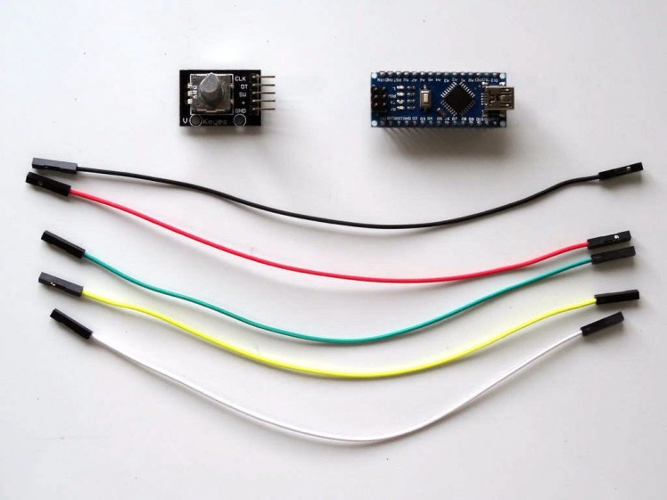
- One Arduino compatible board (I use Arduino Nano, because I have one, but any other will be just fine)
- One Rotary Encoder module I got from this cheap 37 sensors set.
- 5 Female-Female jumper wires
1 / 4 • Picture 1

Picture 1

Picture 2

Picture 3

Picture 4
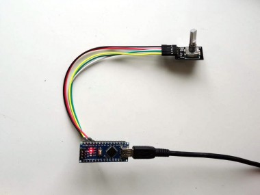
- Connect Ground(Black wire), Power(Red wire), Direction(Green wire), Clock(Yellow wire) and Switch (White wire) to the Rotary Encoder Module (Picture 1)
- Connect the other end of the Ground wire(Black wire) to Ground pin of the Arduino board (Picture 2)
- Connect the other end of the Power wire(Red wire) to the 5V power pin of the Arduino board (Picture 2)
- Connect the Clock wire(Yellow wire) to Digital pin 2 of the Arduino board (Picture 3)
- Connect the Direction wire(Green wire) to Digital pin 3 of the Arduino board (Picture 3)
- Connect the Switch wire(White wire) to Digital pin 4 of the Arduino board (Picture 3)
- Picture 4 shows where are the Ground, 5V Power, Digital 2, Digital 3 and Digital 4 pins of the Arduino Nano.
1 / 2 • Picture 1

Picture 1

Picture 2
To start programming the Arduino, you will need to have the Arduino IDE installed from here: http://www.arduino.cc/ .
Make sure that you install 1.6.7 or higher, otherwise this tutorial will not work!
The Visuino: https://www.visuino.com also needs to be installed.
- Start Visuino as shown in the first picture
- Click on the "Tools" button on the Arduino component (Picture 1) in Visuino
- When the dialog appears, select Arduino Nano as shown in Picture 2
1 / 3 • Picture 1

Picture 1

Picture 2

Picture 3
To use the EEPROM Module of the Arduino component, we need to add element to it where we will store the value. We can add multiple elements of different types. In our case since we will store Integer data, we will add Integer element. In addition, the button(Switch) of the Rotary Encoder I used does not have built-in pull up resistor, so we will enable the Arduino pull up resistor for Digital Pin 4 where the button is connected:
- In the Object Inspector, expand the "Modules" property, then expand the "EEPROM" sub-property, and click on the "..." button next to the value of the "Elements" property (Picture 1)
- In the "Elements" editor select “Integer”, and then click on the "" button to add one Integer Element (Picture 2)
- Close the "Elements" dialog
- In the Object Inspector, expand the "Digital" property, then expand the "Digital[ 4 ]", then set the value of the "Is Pull Up" property to "True" (Picture 3)
1 / 4 • Picture 1

Picture 1

Picture 2

Picture 3

Picture 4
To read the data from the Rotary Encoder, we will add and connect a Visuino component:
- Type "rotary" in the Filter box of the Component Toolbox then select the "Rotary Encoder Sensor" component (Picture 1), and drop it in the design area
- Optionally, in the Object Inspector, set the value of the "Debounce Interval" property to "5" (Picture 2) This will suppress the bouncing noise on some rotary encoders. If your encoder is not noisy, you can leave the value of this property as "0".
- Connect the "Out" pin of the Digital[ 2 ] channel of the Arduino component to the "Clock(A)" pin of the RotaryEncoderSensor1 (Picture 3)
- Connect the "Out" pin of the Digital[ 3 ] channel of the Arduino component to the "Direction(B)" pin of the RotaryEncoderSensor1 (Picture 4)
1 / 5 • Picture 1

Picture 1

Picture 2

Picture 3

Picture 4

Picture 5
We will add a counter to count the pulses from the rotary encoder. We also need to set a value from the EEPROM into the counter when the power is turned on. For this we will need to add "Set Value" element to the Counter, and add pin to its Value property:
- Type "count" in the Filter box of the Component Toolbox then select the "Up/Down Counter" component (Picture 1), and drop it in the design area
- Click on the "Tools" button of the UpDownCounter1 component (Picture 2)
- In the "Elements" editor select the “Set Value” element, and then click on the "" button on the left to add a "Set Value" Element (Picture 3)
- In the Object Inspector click on the Pin button at front of the "Value" property (Picture 4), and select "Integer SinkPin" (Picture 5)
- Close the "Elements" dialog.
1 / 5 • Picture 1

Picture 1

Picture 2

Picture 3

Picture 4

Picture 5
- Connect the "Up" pin of the RotaryEncoderSensor1 component to the "Up" pin of the UpDownCounter1 component (Picture 1)
- Connect the "Down" pin of the RotaryEncoderSensor1 component to the "Down" pin of the UpDownCounter1 component (Picture 2)
- Connect the "Out" pin of the "Modules.EEPROM.Elements.Integer1" element of the Arduino component to the "Value" input pin of the "Elements.Set Value1" element of the UpDownCounter1 component (Picture 3)
- Connect the "Out" pin of the UpDownCounter1 component to the "In" input pin of the "Modules.EEPROM.Elements.Integer1" element of the Arduino component (Picture 4)
- Connect the "Out" pin of the UpDownCounter1 component to the "In" input pin of the "Serial[ 0 ]" channel of the Arduino component (Picture 5)
1 / 5 • Picture 1

Picture 1

Picture 2

Picture 3

Picture 4

Picture 5
We will use the Button(Switch) of the Rotary Encoder (pressing the axle down) to save the current value of the counter into the EEPROM. Since the button has default value of True, and value of False when pressed, we will invert it. The buttons usually have a bouncing noise when pressed or released. I already made Tutorial on how to remove the noise, and here we will use the same Debounce Button component to remove the noise:
- Type "button" in the Filter box of the Component Toolbox then select the "Debounce Button" component (Picture 1), and drop it in the design area
- Type "invert" in the Filter box of the Component Toolbox then select the "Boolean Inverter (Not)" component (Picture 2), and drop it in the design area
- Connect the "Out" pin of the Digital[ 4 ] channel of the Arduino component to the "In" pin of the Button1 component (Picture 3)
- Connect the "Out" pin of the Button1 component to the "In" pin of the Inverter1 component (Picture 4)
- Connect the "Out" pin of the Inverter1 component to the "Remember" input pin of the "Modules.EEPROM.Elements.Integer1" element of the Arduino component (Picture 5)
1 / 5 • Picture 1

Picture 1

Picture 2

Picture 3

Picture 4

Picture 5
We want to load the value stored in the EEPROM into the counter as soon as the Arduino code starts executing. For this we can use the "Start" component. It generates a clock event when the Arduino code starts executing. We also want to load the Value of the Set Value element first, and then set that value to the counter. To do this we need the events to happen in specific order. We can use the "Clock Multi Source" to generate multiple events in specified order:
- Type "start" in the Filter box of the Component Toolbox then select the "Start" component (Picture 1), and drop it in the design area
- Type "clock" in the Filter box of the Component Toolbox then select the "Clock Multi Source" component (Picture 2), and drop it in the design area
- Connect the "Out" pin of the Start1 component to the to the "In" input pin of the ClockMultiSource1 component (Picture 3)
- Connect the "Pin[ 0 ]" output pin of the ClockMultiSource1 component, to the "Recall" input pin of the "Modules.EEPROM.Elements.Integer1" element of the Arduino component (Picture 4)
- Connect the "Pin[ 1 ]" output pin of the ClockMultiSource1 component, to the "in" input pin of the "Elements.Set Value1" element of the UpDownCounter1 component (Picture 5)
1 / 2 • Picture 1

Picture 1

Picture 2
- In Visuino, Press F9 or click on the button shown on Picture 1 to generate the Arduino code, and open the Arduino IDE
- In the Arduino IDE, click on the Upload button, to compile and upload the code (Picture 2)
1 / 6 • Picture 1

Picture 1

Picture 2

Picture 3

Picture 4

Picture 5

Picture 6
You can see the connected and running project on Picture 1.
On Picture 2 you can see the complete Visuino diagram.
- If you open Serial Terminal in the Arduino IDE or Visuino, you will see the initial value of the counter being reset to Zero (Or whatever was stored in the EEPROM before) (Picture 3)
- If you rotate the Rotary Encoder, you will see the counter value changing (Picture 4)
- If you press the axle of the Rotary Encoder down, the current value of the counter will be saved into the EEPROM
- If you power down the Arduino, and then power it up again and connect the with Serial Terminal, you will see that the Counter will be initialized with the value saved in the EEPROM (Picture 5) and in my case will immediately change from 0 to 23 (The value I saved in the EEPROM)
- You can continue changing the Counter by rotating the Rotary Encoder (Picture 6)
Congratulations! You have learned how to read and write values into the Arduino's EEPROM with Visuino.
Also attached is the Visuino project, that I created for this tutorial. You can download and open it in Visuino: https://www.visuino.com
Credits
Related products


Leave your feedback...