

Rs485 Serial Communication Between Arduinos With Visuino

About the project
Easily connect Arduino boards at a great distance over RS485 with Visuino.
Project info
Difficulty: Easy
Estimated time: 1 hour
License: GNU General Public License, version 3 or later (GPL3+)
Items used in this project
Hardware components

Software apps and online services
Story
Sometimes we need to connect Arduino boards located far away from each other. The RS485 is a very convenient way to connect the boards with just 2 wires, and can work to a distance of 1200m (4000 ft). It also allows multiple boards to be connected easily to the same 2 wires. The downside is that the channel is shared between multiple devices, and only one of them can transmit at a time.
It is very easy to connect Arduino boards with RS485. There are cheap readily available, easy to use modules based on the Maxim Integrated MAX485 chip, and with the help of Visuino a graphical development environment for Arduino it is also very easy to program the communication.
In this Tutorial I will show you how easy it is to connect Arduino Nano and Arduino Mega with RS485, and have the Arduino Nano send data from a sensor to the Arduino Mega, and the Arduino Mega to control the LED on the Arduino Nano, while also sending the data received from the Nano to a Serial Terminal.
Components
1 / 2 • Picture 1

Picture 1

Picture 2
- OneArduino compatible board (I use Arduino Nano, because I have one, but any other will be just fine)
- One Arduino Mega 2560, or other board with 2 or more Serial ports
- One10K Potentiometer
- Two MAX485 RS-485 Modules
- 9 Female-Female jumper wires
- 4 Female-Male jumper wires
- 1 Male-Male jumper wires
- 2Jumpers with open top (Picture 2) allowing a wire to be inserted from the top side between the pins
1 / 3 • Picture 1

Picture 1

Picture 2

Picture 3
- Connect the Male end of one of the Female-Male jumper wires (Black wire) to the Ground pin of the Arduino Mega (Picture 1)
- Connect the Male end of another one of the Female-Male jumper wires (Red wire) to the 5V Power pin of the Arduino Mega (Picture 1)
- Connect the Male-Male jumper wire (Blue wire) to the Digital pin 2 of the Arduino Mega (Picture 2)
- Connect the Male end of another one of the Female-Male jumper wires (Green wire) to the TX1 (Serial 1 Transmit) pin of the Arduino Mega (Picture 2)
- Connect the Male end of another one of the Female-Male jumper wires (Yellow wire) to the RX1 (Serial 1 Receive) pin of the Arduino Mega (Picture 2)
- Picture 3 shows where are the Ground, 5V Power, Digital 2, RX1, and TX1, pins of the Arduino Mega
1 / 4 • Picture 1

Picture 1

Picture 2

Picture 3

Picture 4
- Connect one of the Female-Female jumper wires (Black wire) to the Ground pin of the Arduino Nano (Picture 1)
- Connect another one of the Female-Female jumper wires (Red wire) to the 5V Power pin of the Arduino Nano (Picture 1)
- Connect the Female end of a Female-Male jumper wires (Blue wire) to the Digital pin 2 of the Arduino Nano (Picture 2 and 3)
- Connect another one of the Female-Female jumper wires (Yellow wire) to the RX (Serial Receive) pin of the Arduino Nano (Picture 2 and 3)
- Connect another one of the Female-Female jumper wires (Green wire) to the TX (Serial Transmit) pin of the Arduino Nano (Picture 2 and 3)
- Picture 4 shows where are the Ground, 5V Power, Digital 2, RX, and TX, pins of the Arduino Nano
1 / 4 • Picture 1

Picture 1

Picture 2

Picture 3

Picture 4
- Connect a Female-FemalePower wire(Red wire) to the one end pin of the Potentiometer (Picture 1)
- Connect a Female-FemaleSignal wire(Brown wire) to the Wiper(center) pin of the Potentiometer (Picture 1)
- Connect a Female-FemaleGround wire(Black wire) to the other end pin of the Potentiometer (Picture 1)
- Connect the other end of the Power wire(Red wire) to the REF (5V) pin of the Arduino Nano board (Picture 2)
- Connect the other end of the Signal wire(Brown wire) to the Analog pin 0 of the Arduino Nano board (Picture 2)
- Connect the other end of the Ground wire(Black wire) to the Ground pin of the Arduino Nano board (Picture 3)
- Picture 4 shows in Red the Arduino Nano pins that ware connected in this step. The picture also shows the pins connected in Step 2 in Blue
1 / 4 • Picture 1

Picture 1

Picture 2

Picture 3

Picture 4
- Connect the other end of the Ground wire(Black wire) from the Arduino Mega to the GND(Ground) pin of the RS485 Module (Picture 1)
- Connect the other end of the Power wire(Red wire) from the Arduino Mega to the VCC(Power) pin of the RS485 Module (Picture 1)
- Place a jumper between the DE and RE pins of the RS485 Module (Picture 2)
- Connect the other end of the TX wire(Green wire) from the Arduino Mega to the DI(Driver Input) pin of the RS485 Module (Picture 3)
- Connect the other end of the RX wire(Yellow wire) from the Arduino Mega to the RO(Receiver Output) pin of the RS485 Module (Picture 3)
- Connect the other Male end of the Digital Pin 2 wire (Blue wire) from the Arduino Mega to the center of the Jumper between the DE and RE pins of the RS485 Module (Picture 4). Make sure the wire has a good electrical connection with the metal plate in the jumper
- Repeat the same steps from 1 to 6 for the other RS485 Module and the Arduino Nano board
1 / 4
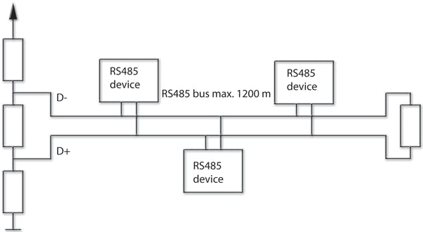


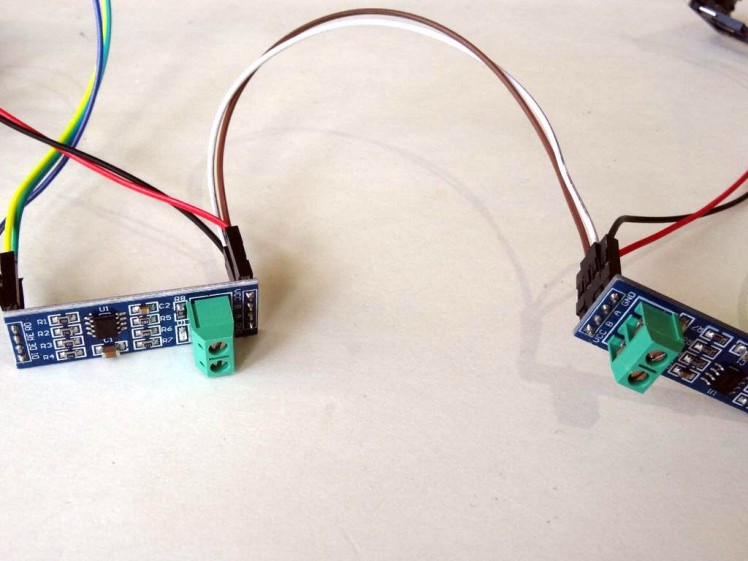
The RS485 uses only 2 wires. Every device is connected to the 2 wires (Picture 1). There are some resistors that are needed, however the MAX485 Modules that we use have these resistors already installed, so we can directly connect the modules with just 2 wires.
- Connect one end of a Female-Female jumper wire - A wire(White wire) to the "A" pin of one of the RS485 Modules (Picture 2 and 3)
- Connect one end of another Female-Female jumper wire - B wire(Brown wire) to the "B" pin of one of the RS485 Modules (Picture 2 and 3)
- Connect other end of a A wire(White wire) to the "A" pin of the other RS485 Module (Picture 2 and 3 and 4)
- Connect other end of a B wire(Brown wire) to the "B" pin of the other RS485 Module (Picture 2 and 3 and 4)
1 / 2 • Picture 1

Picture 1

Picture 2
Please be aware that there are some critical bugs in Arduino IDE 1.6.6. Make sure that you install 1.6.7 or higher, otherwise this Tutorial will not work!
- Start Visuino as shown in the first picture
- Click on the "Tools" button on the Arduino component (Picture 1) in Visuino
- When the dialog appears, select "Arduino Nano" as shown in Picture 2
1 / 6 • Picture 1

Picture 1

Picture 2

Picture 3

Picture 4

Picture 5

Picture 6
We will send to the serial the value of Analog Channel 0 once a second. For this we need to use "Analog Snapshot" component, and to clock it once a second with the "Clock Generator":
- Type "snap" in the Filter box of the Component Toolbox then select the "Analog Snapshot" component (Picture 1), and drop it in the design area
- Connect the "Out" pin of the "Digital[ 14 ]/AnalogIn[ 0 ]" channel of the Arduino component to the "In" pin of the AnalogSnapshot1 component (Picture 2)
- Connect the "Out" output pin of the AnalogSnapshot1 component (Picture 3) to the "In" input pin of the "Serial[ 0 ]" channel of the Arduino component (Picture 4)
- Type "clock" in the Filter box of the Component Toolbox then select the "Clock Generator" component (Picture 5), and drop it in the design area
- Connect the "Out" output pin of the ClockGenerator1 component to the "In" input pin of the AnalogSnapshot1 component (Picture 6)
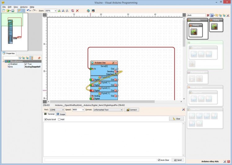
The RS485 uses the same shared channel for both sending and receiving data. It is a Simplex line. This means that the board can't send and receive data at the same time, and the RS485 module needs to be switched between transmitting and receiving mode. The Serial port of the Arduino component in Visuino has a pin indicating that the port is sending data. We will use this pin to control the direction (Transmit/Receive) of the RS485 module.
- Connect the "Sending" output pin of the "Serial[ 0 ]" channel of the Arduino component to the "Digital" input pin of the "Digital[ 2 ]" channel of the Arduino component (Picture 1)
1 / 2 • Picture 1

Picture 1

Picture 2
We will receive 2 text commands ("on" and "off") through the Serial port controlling the LED on pin 13. The commands will arrive as text followed by enter. To decode the "on" command we first will construct a text from the arriving characters followed by Enter/New Line by using a "Char To Text" component:
- Type "char" in the Filter box of the Component Toolbox then select the "Char To Text" component (Picture 1), and drop it in the design area
- Connect the "Out" pin of the "Serial[ 0 ]" channel of the Arduino component to the "In" pin of the CharToText1 component
1 / 5 • Picture 1

Picture 1

Picture 2

Picture 3

Picture 4

Picture 5
Now that we have the text we need to check if it is "on" or "off". To do this it is enough to check just for "on". For this, we will use "Compare Text Value" component:
- Type "compare" in the Filter box of the Component Toolbox then select the "Compare Text Value" component (Picture 1), and drop it in the design area
- In the Object Inspector, set the value of the "Value" property to "on" (Picture 2)
- Connect the "Out" pin of the CharToText1 component to the to the "In" pin of the CompareTextValue1 component (Picture 3)
- Connect the "Out" output pin of the CompareTextValue1 component (Picture 4) to the "Digital" input of the "Digital[ 13 ]" channel of the Arduino component (Picture 5)
1 / 4 • Picture 1

Picture 1

Picture 2

Picture 3

Picture 4
- In Visuino, Press F9 or click on the button shown on Picture 1 to generate the Arduino code, and open the Arduino IDE
- Connect the Arduino Nano with the USB cable to the computer
- In the Arduino IDE select the board type as Arduino Nano (Picture 2)
- In the Arduino IDE select the serial port to which the Arduino Nano board is connected (Picture 3)
- In the Arduino IDE, click on the Upload button, to compile and upload the code (Picture 4)
1 / 2 • Picture 1

Picture 1

Picture 2
- Start a new Visuino project as shown in the first picture
- Click on the "Tools" button on the Arduino component (Picture 1) in Visuino
- When the dialog appears, select "Arduino Mega 2560" as shown in Picture 2
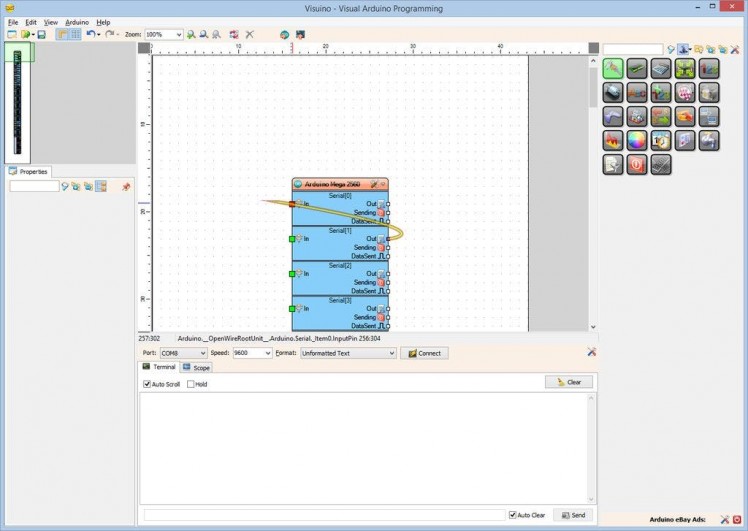
We will send the serial data that we receive from the RS485 module on Serial Port 1 to the computer trough Serial Port 0 . For this we need to connect the two ports:
- Connect the "Out" output pin of the "Serial[ 1 ]" channel of the Arduino component to the "In" input pin of the "Serial[ 0 ]" channel of the Arduino component (Picture 4)
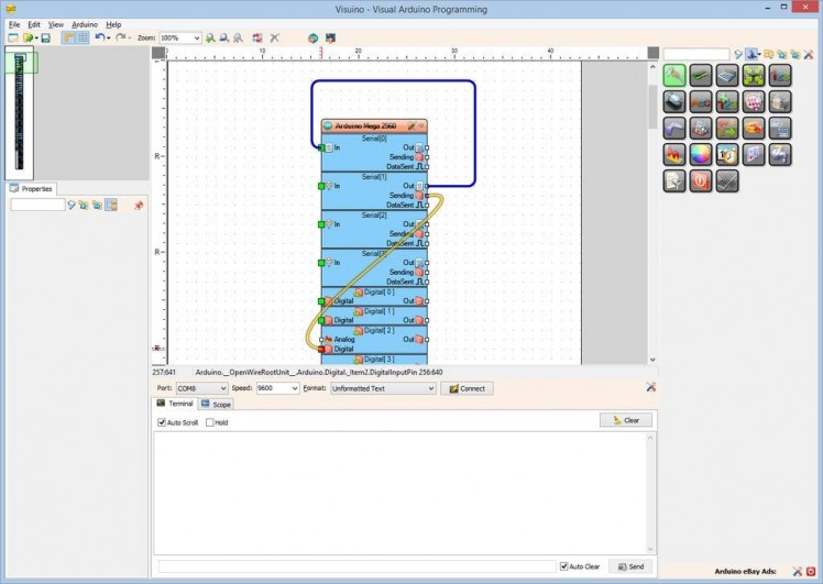
Since the RS485 uses the same shared channel for both sending and receiving data we will use the "Sending" pin of the Serial Channel 1 to control the direction (Transmit/Receive) of the RS485 module:
- Connect the "Sending" output pin of the "Serial[ 1 ]" channel of the Arduino component to the "Digital" input pin of the "Digital[ 2 ]" channel of the Arduino component (Picture 1)
1 / 3 • Picture 1

Picture 1

Picture 2

Picture 3
We want to send "on"/"off" command for the LED to flip it after every value we receive over the RS485. Since the RS485 is simplex, it is better to wait for it to properly switch before we send any data. For this we can use a Delay component set to 100 Milliseconds (100000 Microseconds):
- Type "delay" in the Filter box of the Component Toolbox then select the "Delay" component (Picture 1), and drop it in the design area
- In the Object Inspector, set the value of the "Interval" property to "100000" (Picture 2)
- Connect the "Out" pin of the "Serial[ 1 ]" channel of the Arduino component to the "In" pin of the Delay1 component (Picture 3)
1 / 2 • Picture 1

Picture 1

Picture 2
We want to switch between "on", and "off" command every time a new text arrives over the serial. To do that we need to use a Flip-Flop. The most convenient for this purpose is the Toggle(T)-FlipFlop:
- Type "flip" in the Filter box of the Component Toolbox then select the "Toggle(T) Flip-Flop" component (Picture 1), and drop it in the design area
- Connect the "Out" pin of the Delay1 to the "In" pin of the TFlipFlop1 (Picture 2)
1 / 5 • Picture 1

Picture 1

Picture 2

Picture 3

Picture 4

Picture 5
The Flip-Flop will generate Digital(Boolean) value switching between True and False. We need to convert this into "on" and "off" text. For this we will use "Digital To Text" component:
- Type "To Text" in the Filter box of the Component Toolbox then select the "Digital To Text" component (Picture 1), and drop it in the design area
- In the Object Inspector, set the value of the "FalseValue" property to "off" (Picture 2)
- In the Object Inspector, set the value of the "TrueValue" property to "on" (Picture 3)
- Connect the "Out" pin of the TFlipFlop1 component to the "In" pin of the DigitalToText1 component (Picture 4)
- Connect the "Out" output pin of the DigitalToText1 component to the "In" input pin of the "Serial[ 1 ]" channel of the Arduino component (Picture 4)
1 / 4 • Picture 1

Picture 1

Picture 2

Picture 3

Picture 4
- In Visuino, Press F9 or click on the button shown on Picture 1 to generate the Arduino code, and open the Arduino IDE
- Connect the Arduino Mega with the USB cable to the computer
- In the Arduino IDE select the board type as Arduino Mega (Picture 2)
- In the Arduino IDE select the serial port to which the Arduino Mega board is connected (Picture 3)
- In the Arduino IDE, click on the Upload button, to compile and upload the code (Picture 4)
1 / 5 • Picture 1

Picture 1

Picture 2

Picture 3

Picture 4

Picture 5
Congratulations! You have implemented RS485 communication between 2 Arduino boards.
Picture 1 and the Video show the connected and powered up project.
If you connect to the Arduino Mega with Serial Terminal or Visuino you will see the position of the potentiometer displayed in text form (Picture 2). In Visuino you can also see it plotted in the Scope (Picture 3) . If you turn the Potentiometer the values will change. The LED on the Arduino Nano will also turn On and Off every second, when new data is received by the Arduino Mega.
On Picture 4 you can see the complete Visuino diagram for the Arduino Nano.
And on Picture 5 you can see the complete Visuino diagram for the Arduino Mega.
Also attached are the Visuino projects, that I created for this Tutorial. You can download and open them in Visuino: https://www.visuino.com
Credits
Related products


Leave your feedback...