
Roamer, The Self Charging Companion Robot

Made by electrouser778 / 3D Printing / Robotics
About the project
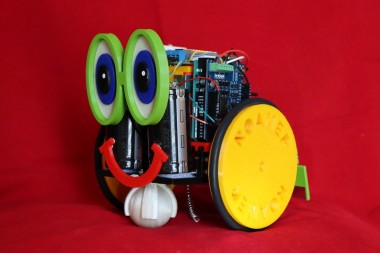
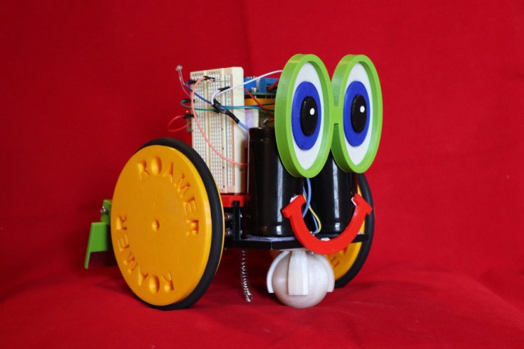
Roamer is a self-charging, switch free, capacitor powered, wandering robot companion.
Project info
Difficulty: Moderate
Platforms: Arduino
Estimated time: 1 day
License: GNU General Public License, version 3 or later (GPL3+)
Items used in this project
Hardware components

View all
Story

Details
---------- Redefine Robots ----------
Set Roamer on a charging station. When charged, she wanders around randomly, sometimes coming into the charging station and topping off. When the room gets dark (night), Roamer “rests” on the charging station. At dawn (light), she resumes her journey to nowhere, charging at every opportunity.
Here is a real time view in action.
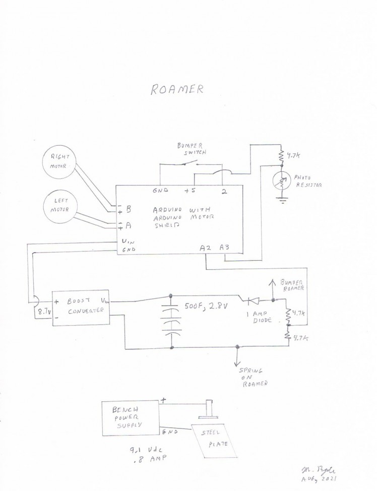
Here's the schematic.

Project Logs
Stepper Motor to Drive Wheels
Now I'm trying a thin Nema 17 stepper motor to replace the geared dc wheel driver motor--it works!
I'm driving the motor with an Arduino motor shield--motor pin 1 to B-; motor pin 4 to B+; motor pin 6 to A-; motor pin 3 to A+.
Code (stepper motor short) follows:
int delaylength=10;
int volt=220;

void setup() {
  pinMode(12,OUTPUT);
  pinMode(13,OUTPUT);
  pinMode(9,OUTPUT);
  pinMode(8,OUTPUT);

}

void loop() {

  //round 1
  digitalWrite(9,LOW);
  digitalWrite(8,HIGH);

  digitalWrite(12,HIGH);
  analogWrite(3,volt);

  delay(delaylength);


  digitalWrite(9,HIGH);
  digitalWrite(8,LOW);

  digitalWrite(13,LOW);
  analogWrite(11,volt);

  delay(delaylength);

 digitalWrite(9,LOW);
  digitalWrite(8,HIGH);

  digitalWrite(12,LOW);
  analogWrite(3,volt);

  delay(delaylength);

  digitalWrite(9,HIGH);
  digitalWrite(8,LOW);

  digitalWrite(13,HIGH);
  analogWrite(11,volt);

  delay(delaylength);

//end round 1

}
I supplied 10 volts dc with one amp capacity to the motor shield power input.
Good News/Bad News
The good news is that Roamer has run for quite a while, with never a failure to find the charging station. Like a turtle, Roamer has wound up with wheels off the ground a few times (I think I know how to solve that issue).
The bad news is that running for many hours takes a toll on little dc motors--shall we say failure?
There are no brushes in these little motors, merely little "fingers" that wear out rather quickly.
A dc motor with genuine brushes would probably last longer--but a robot that buzzes around twelve to fourteen hours a day is going to strain a brushed motor.
I'm testing a stepper motor to see if that might provide the reliability I want. A companion robot needs to run a long time without serious maintenance. I have more work to do.
Software
When Roamer's bumper is depressed, there are five possible "backup and turn" scenarios--the activation choice is random.
After 30 seconds of forward movement (stuck spinning wheels without depressing the bumper or long distance), she backs up and tries another direction.
unsigned long timestart;
unsigned long timeend;
unsigned long timetotal;

int a=95;//speed for left? motor, increased from 80
int b=85;
int c=650;//value for photoresistor day/night higher = less light to keep going
int d=820;//upper voltage value

int t1=1;

int volt=A1;//bumper input pin
int val=0;//initial bumper value
int val1=100;//initial value for photocell

int bumper=1;//setup bumper not pressed
long randNumber;
int x=1;//current read value to be determined in setup
int x1=0;//first of multiple reads
int x2=0;
int x3=0;
int x4=0;
int x5=0;

int y=0;//counts for overcurrent rather than spike
int z=0;//storage area for temporary current reads

const int pwmA=3;
const int pwmB=11;
const int brakeA=9;
const int brakeB=8;
const int dirA=12;
const int dirB=13;

void setup() {

  pinMode (dirA,OUTPUT);
  pinMode (brakeA,OUTPUT);
  pinMode (dirB,OUTPUT);
  pinMode (brakeB,OUTPUT);
  pinMode (A1,INPUT);


  pinMode (2,INPUT);
  digitalWrite (2,HIGH);
  randomSeed (analogRead(0));

  digitalWrite(brakeA,LOW);
  digitalWrite(brakeB,LOW);

   digitalWrite(dirA,HIGH);
  digitalWrite(dirB,HIGH);
  analogWrite(pwmA,0);//changed to reflect no overcurrent mode
  analogWrite(pwmB,0);
  //delay(2000);//get motors started
  //x1=analogRead(A0);//set normal motor value
  //delay(10);
  //x2=analogRead(A0);
  //delay(10);
  //x3=analogRead(A0);
  //delay(10);
  //x4=analogRead(A0);
  //delay(10);
  //x5=analogRead(A0);

  //x=((x1+x2+x3+x4+x5)/5);
  x=500;//arbitray number

  timestart=millis();

}

void loop() {

  bumper=digitalRead(2);
  if (bumper==0) {//bumper depressed
  randNumber=random(1,5);//changed august 12 from 1,4

  if(randNumber==1) {

    analogWrite(pwmB,0);//check for power station
    analogWrite(pwmA,0);
    delay(500);//stop to read
    val=analogRead(A2);
    if (val>100) {
      val1=analogRead(A3);
      while ((val<d && val>100) || (val1>c)) {//was 815 instead of 600
       val1=analogRead(A3);
        val=analogRead(A2);
        delay(100);
      }}


    digitalWrite(dirA,LOW);
    digitalWrite(dirB,LOW);//reverse
    analogWrite(pwmA,120);//was 150
    analogWrite(pwmB,70);//reverse power
    delay(500);
    analogWrite(pwmB,0);
    delay(750);
    analogWrite(pwmA,0);//stop

    digitalWrite(dirA,HIGH);
  digitalWrite(dirB,HIGH);
  analogWrite(pwmA,a);
  analogWrite(pwmB,b);
  delay(1000);

  t1=0;
  timestart=millis();

  }

  if (randNumber==2) {

    analogWrite(pwmB,0);//check for power station
    analogWrite(pwmA,0);
    delay(500);//stop to read
    val=analogRead(A2);
    if (val>100) {
      val1=analogRead(A3);
      while ((val<d && val>100) ||(val1>c)) {
         val1=analogRead(A3);
       val=analogRead(A2);
        delay(100);
      }}

    digitalWrite(dirA,LOW);
    digitalWrite(dirB,LOW);//reverse
    analogWrite(pwmA,70);//was 150
    analogWrite(pwmB,120);//reverse power
    delay(600);
    analogWrite(pwmA,0);
    delay(1000);
    analogWrite(pwmB,0);//stop

    digitalWrite(dirA,HIGH);
  digitalWrite(dirB,HIGH);
  analogWrite(pwmA,a);
  analogWrite(pwmB,b);
  delay(1000);

  t1=0;
  timestart=millis();
  }

  if (randNumber==3) {

    analogWrite(pwmB,0);//check for power station
    analogWrite(pwmA,0);
    delay(500);//stop to read
    val=analogRead(A2);
    if (val>100) {
      val1=analogRead(A3);
      while ((val<d && val>100) || (val1>c)) {
         val1=analogRead(A3);
        val=analogRead(A2);
        delay(100);
      }}

    digitalWrite(dirA,LOW);
    digitalWrite(dirB,LOW);//reverse
    analogWrite(pwmA,a);//was 150
    analogWrite(pwmB,b);//reverse power
    delay(600);
    digitalWrite(dirB,HIGH);
    analogWrite(pwmB,150);
    delay(800);
    analogWrite(pwmA,0);//stop
    analogWrite(pwmB,0);

    digitalWrite(dirA,HIGH);
  digitalWrite(dirB,HIGH);
  analogWrite(pwmA,a);
  analogWrite(pwmB,b);
  delay(1000);

  t1=0;
  timestart=millis();
  }

 if(randNumber==4) {

    analogWrite(pwmB,0);//check for power station
    analogWrite(pwmA,0);
    delay(500);//stop to read
    val=analogRead(A2);
    if (val>100) {
      val1=analogRead(A3);
      while ((val<d && val>100) || (val1>c)) {//was 815 instead of 600
       val1=analogRead(A3);
        val=analogRead(A2);
        delay(100);
      }}


    digitalWrite(dirA,LOW);
    digitalWrite(dirB,LOW);//reverse
    analogWrite(pwmA,a);//was 150
    analogWrite(pwmB,b);//reverse power
    delay(500);
    analogWrite(pwmB,0);
    delay(1000);
    analogWrite(pwmA,0);//stop

    digitalWrite(dirA,HIGH);
  digitalWrite(dirB,HIGH);
  analogWrite(pwmA,a);
  analogWrite(pwmB,b);
  delay(1000);

  t1=0;
  timestart=millis();

  }

   if(randNumber==5) {

    analogWrite(pwmB,0);//check for power station
    analogWrite(pwmA,0);
    delay(500);//stop to read
    val=analogRead(A2);
    if (val>100) {
      val1=analogRead(A3);
      while ((val<d && val>100) || (val1>c)) {//was 815 instead of 600
       val1=analogRead(A3);
        val=analogRead(A2);
        delay(100);
      }}


    digitalWrite(dirA,LOW);
    digitalWrite(dirB,LOW);//reverse
    analogWrite(pwmA,a);//was 150
    analogWrite(pwmB,b);//reverse power
    delay(400);
    analogWrite(pwmB,0);
    delay(800);
    analogWrite(pwmA,0);//stop

    digitalWrite(dirA,HIGH);
  digitalWrite(dirB,HIGH);
  analogWrite(pwmA,a);
  analogWrite(pwmB,b);
  delay(1000);

  t1=0;
  timestart=millis();

  }


}


  //main body of action
  if (t1=0) {
    timestart = millis();
    t1=1;
  }
  if (t1=1) {
    timeend = millis();
    timetotal= (timeend-timestart);
  }
    if (timetotal>30000) {
     digitalWrite(dirA,LOW);
    digitalWrite(dirB,LOW);//reverse
    analogWrite(pwmA,a);//was 150
    analogWrite(pwmB,b);//reverse power
    delay(1000);
    digitalWrite(dirB,HIGH);
    analogWrite(pwmB,150);
    delay(1000);
    analogWrite(pwmA,0);//stop
    analogWrite(pwmB,0);

    digitalWrite(dirA,HIGH);
  digitalWrite(dirB,HIGH);
  analogWrite(pwmA,a);
  analogWrite(pwmB,b);
  delay(1000);

 t1=0;
 timestart=millis();
    }

  digitalWrite(dirA,HIGH);
  digitalWrite(dirB,HIGH);
  analogWrite(pwmA,a);
  analogWrite(pwmB,b);

  z=analogRead(A0);//read current

  if (z>(x+210))  {//turn around and restart
      digitalWrite(dirA,LOW);
    digitalWrite(dirB,LOW);//reverse
    analogWrite(pwmA,150);
    analogWrite(pwmB,150);//reverse power
    delay(1000);
    digitalWrite(dirB,HIGH);
    analogWrite(pwmB,150);
    delay(600);
    analogWrite(pwmA,0);//stop
    analogWrite(pwmB,0);

    digitalWrite(dirA,HIGH);//go forward one second
  digitalWrite(dirB,HIGH);
  analogWrite(pwmA,a);
  analogWrite(pwmB,b);
  delay(1000);

  t1=0;
  timestart=millis();
    }


}
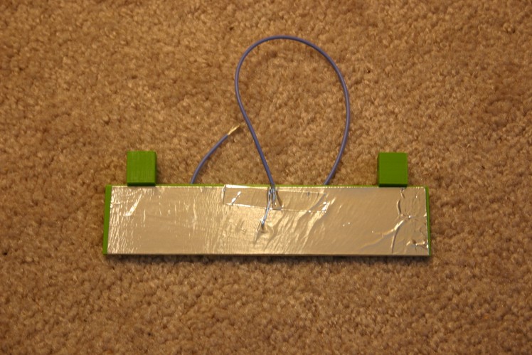
Baseboard Charger
I set up a baseboard charging station--took about five minutes.
Start with an eighteen inch by six inch sheet of steel and an eighteen inch piece of 1 x 2 wood.
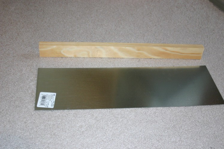
Drill holes (I drilled three) in the edge of the steel.
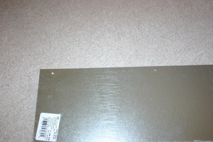
Screw the wood to the steel.
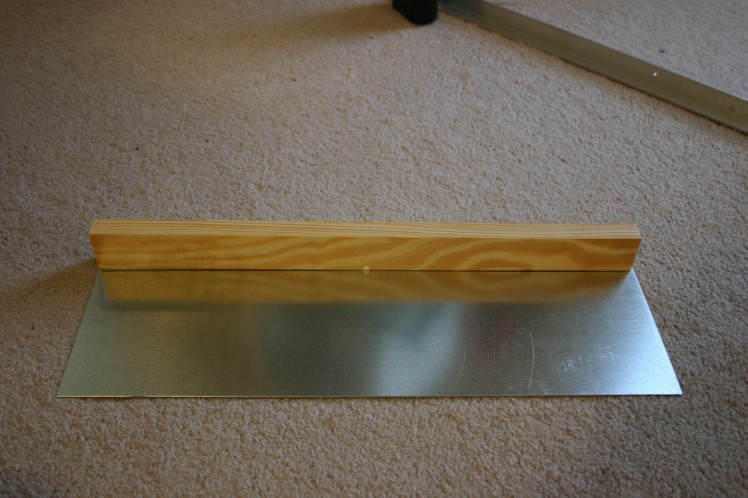
Add aluminum duct tape to the wood, making sure that the tape does not touch the base.
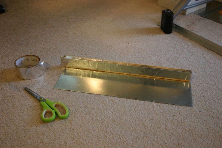
Set against a wall and attach the bench power supply--it's ready to go!
How Roamer was Assembled
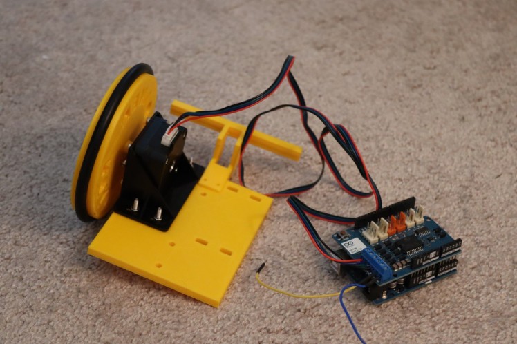
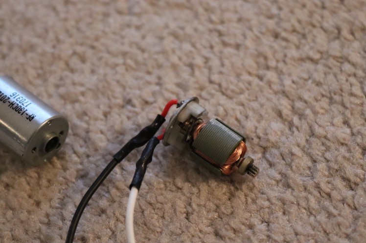
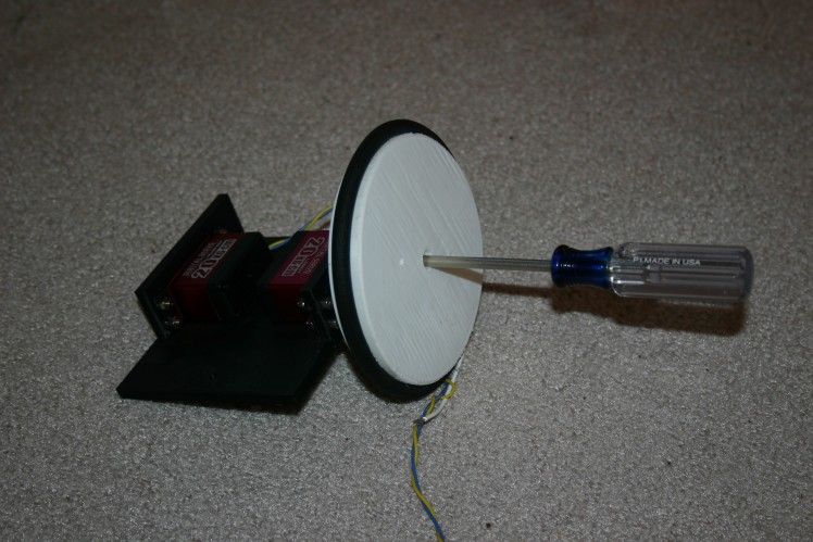
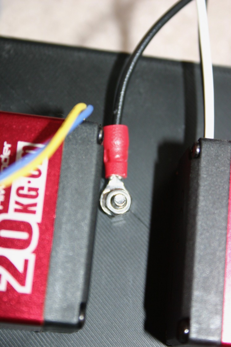
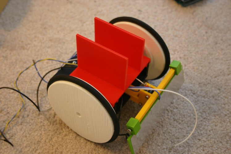
Start with the servo motors--I selected metal gear servos that do not have end stops.
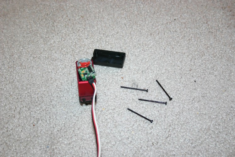
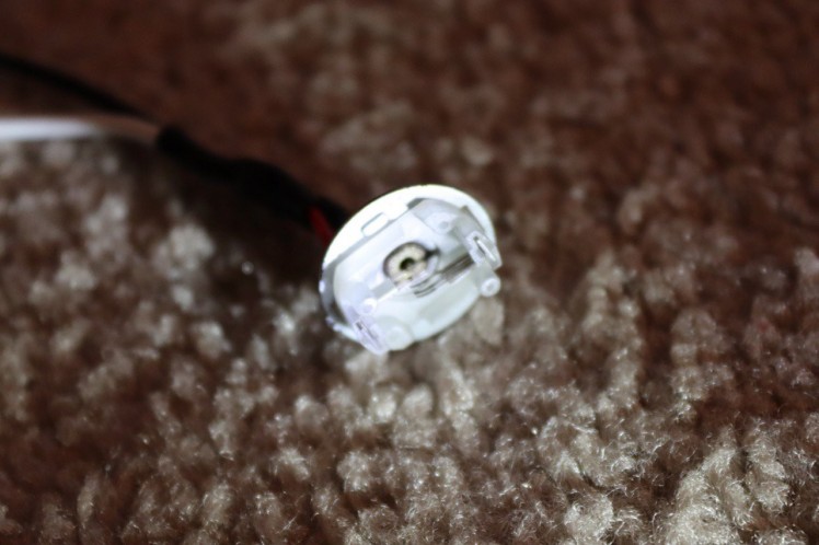
Remove the circuit board.
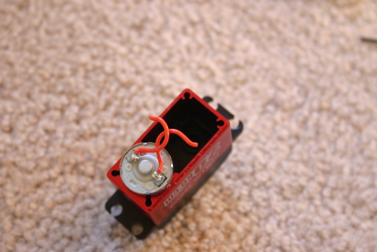
Solder wires to the motor connections.
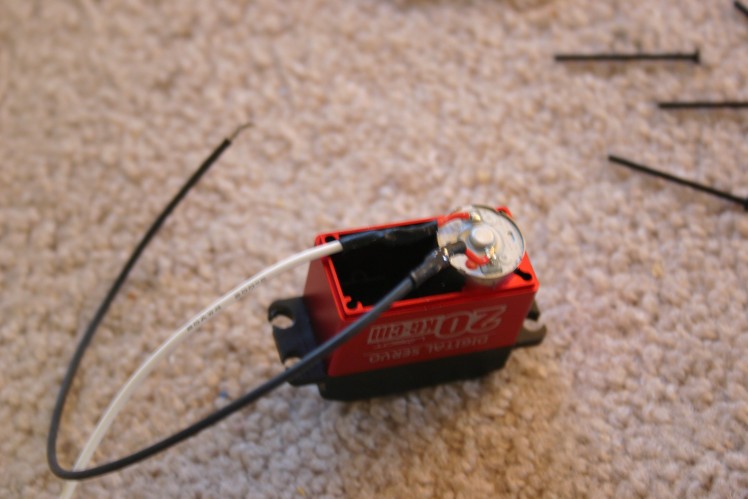
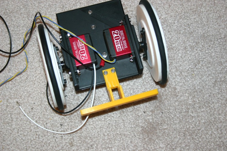
Put the motor back together. Place the vacuum belt (tire) on the wheel.
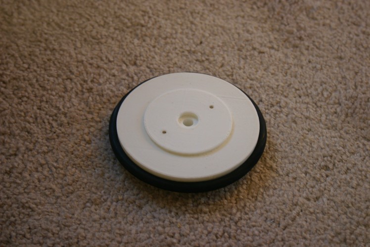
Attach the servo horn to the wheel using 3mm screws.
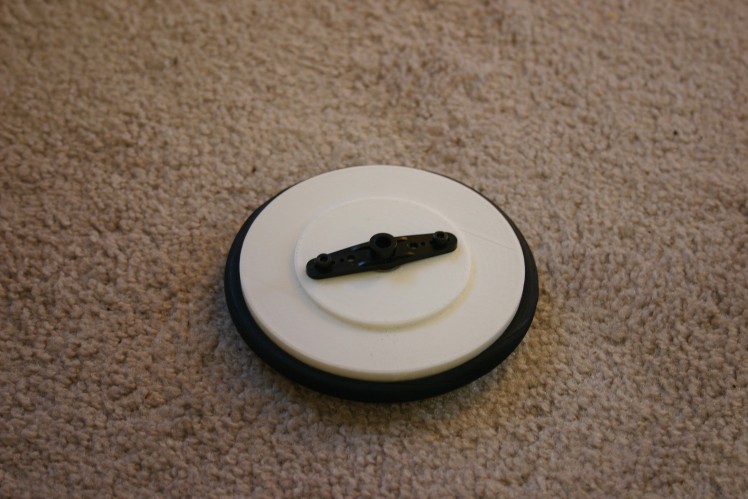
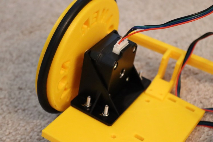
Install the servo motors.
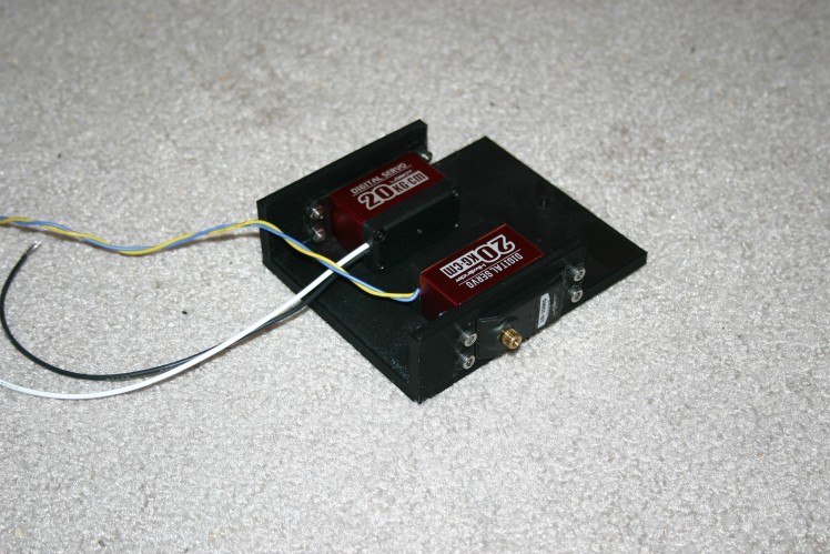
Secure the wheels to the motor shaft.
Repeat.
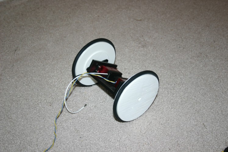
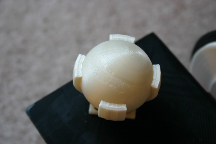
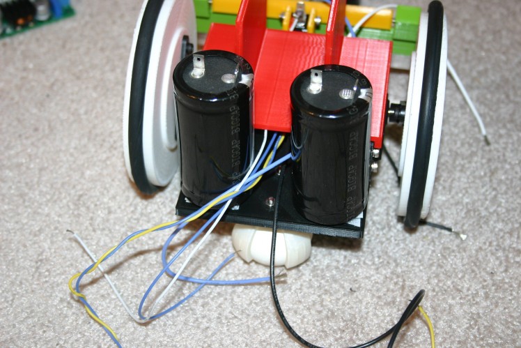
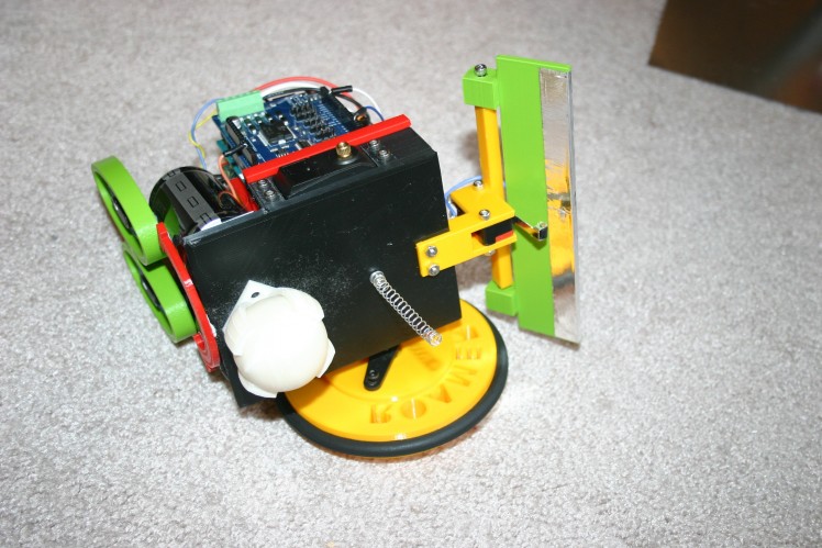
Install the holder for the rear caster ball.
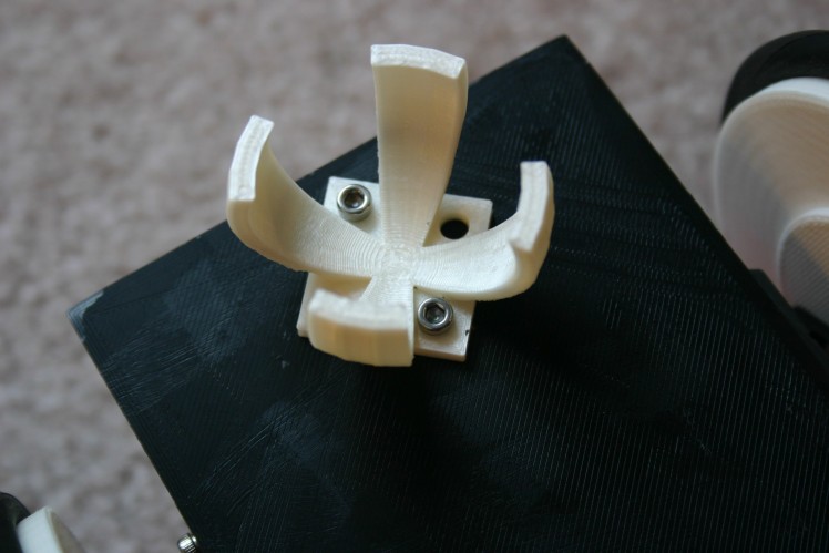
Insert the caster ball.
Insert a 3mm screw into one end of the spring.
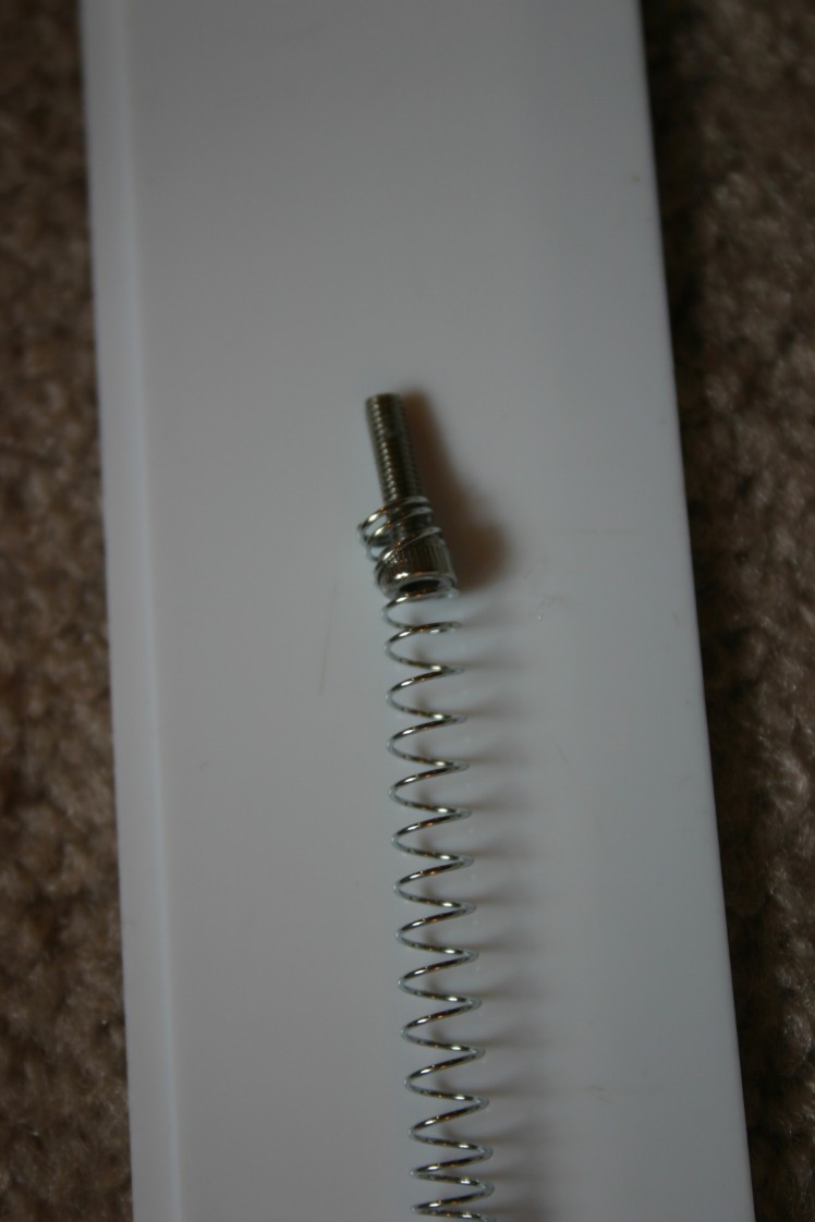
Drill a hole in the base and put the screw through the hole.
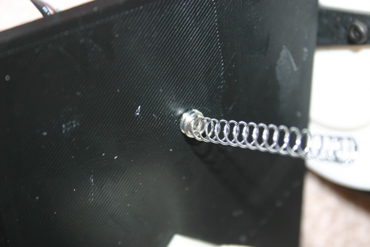
On the other side of the base attach the pickup wire.
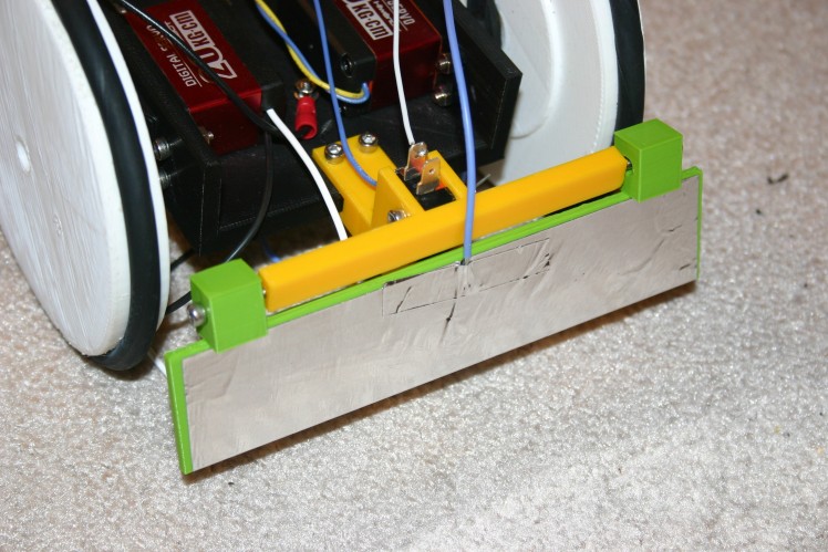
Secure the switch holder to the front of the frame.
Attach aluminum duct tape to the front bumper. Tape a wire (so that it connects to the foil electrically) to the bumper.
Install a lever switch in the switch holder.
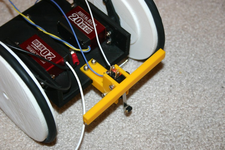
Attach the bumper to the switch holder using 3mm screws.
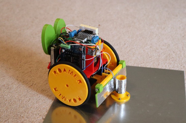
Place the board/capacitor holder onto the frame. Glue together (or lightly melt using a soldering iron).
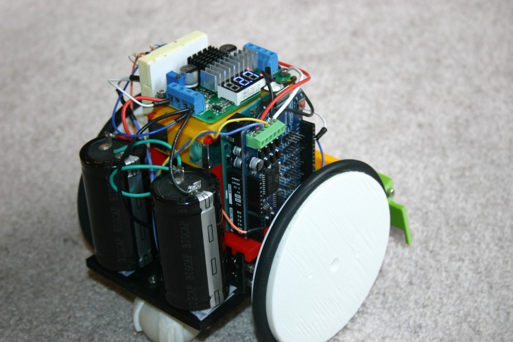
Attach two capacitors to the rear part of the frame using Velcro strips.
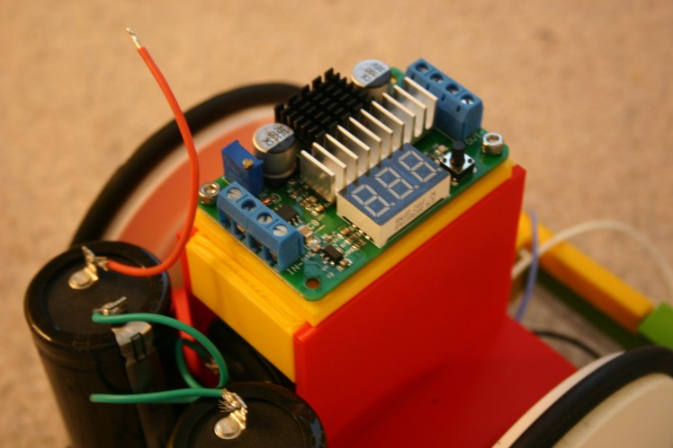
Place the boost converter on the electronics holder.
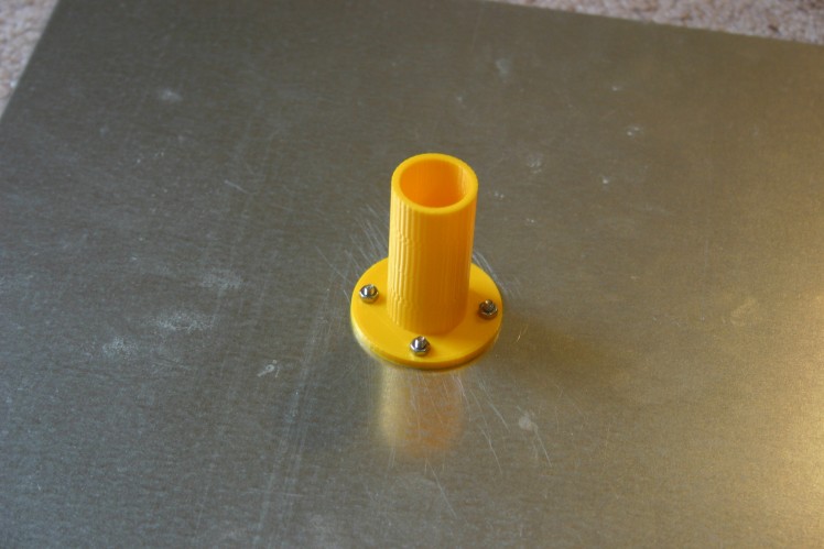
Secure the charge plate pole to the charge base using 3mm screws.
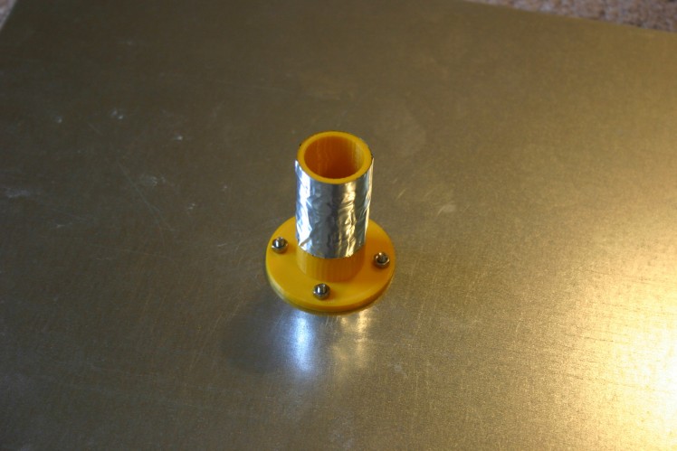
Place foil tape on the pole--not touching the base.
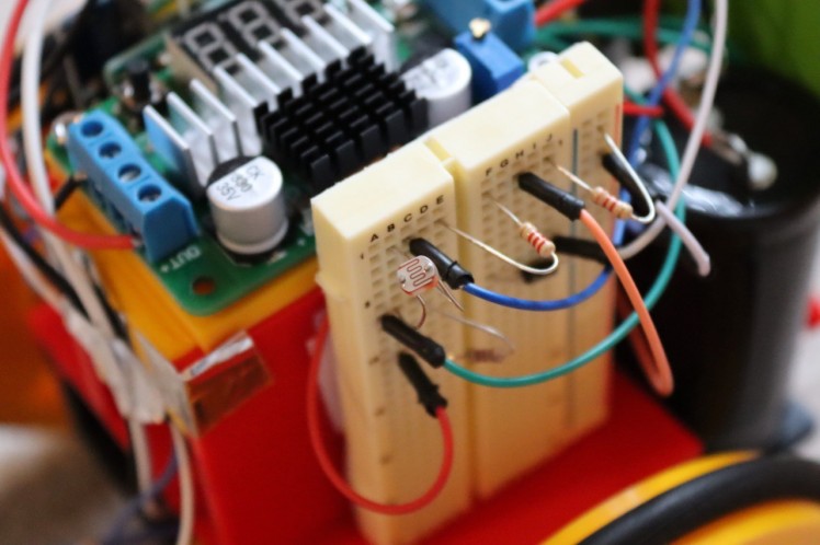
Add the breadboard and wire according to the schematic.
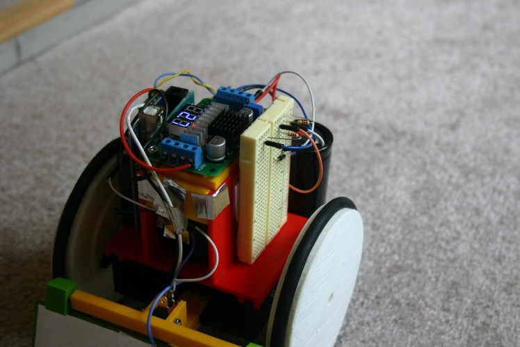
Add the Arduino and motor shield. Secure using Velcro.
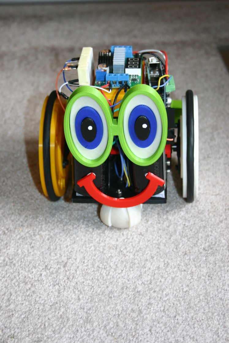
Add the eyes and smile to the back.
The spring and the bumper are the contact points for charging. The bumper should receive positive voltage from the power supply and the spring receives negative.

The photocell enables Roamer to "know" that it is dark--then remain on the charger until morning.
Credits
Related products


Leave your feedback...