
Long Range Controlled Holiday Lighting System Using Nrf21540

Made by knaveen / Holidays / Home Automation / Lights
About the project
This holiday lighting system let users illuminate and control it remotely from far away with a button click.
Project info
Difficulty: Moderate
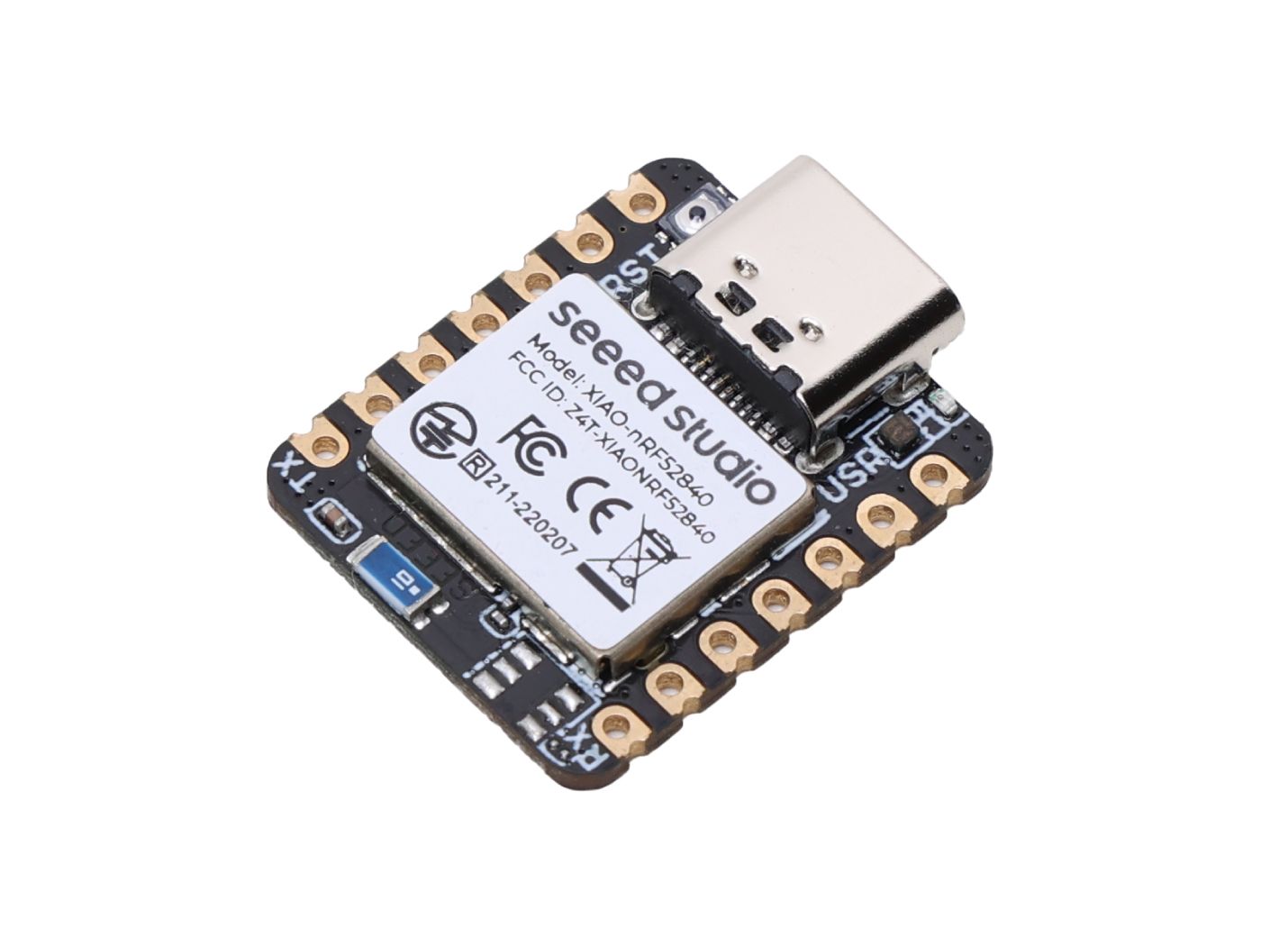
Platforms: Seeed Studio, M5Stack, Nordic Semiconductor
Estimated time: 1 day
License: GNU General Public License, version 3 or later (GPL3+)
Items used in this project
Hardware components

Story
Overview
The holidays are a joyous time full of visits from friends and family, food, and festive decorations. For most people, getting in the holiday mood includes hanging lights, a task that often comes with the frustrations of tangled wires, colors that don’t pop, or even worse to control it at will. I always wanted to control lighting systems remotely from outside my apartment and sometimes from far away. In this project, I am going to make a lighting system that can be controlled over a BLE connection by clicking a button.
Hardware Selection
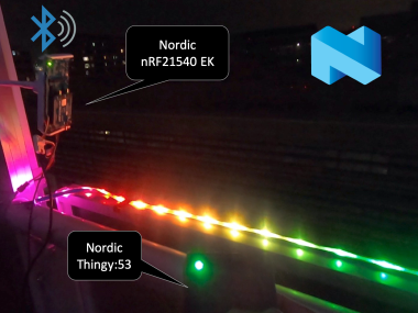
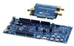
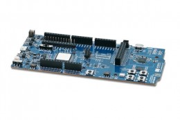
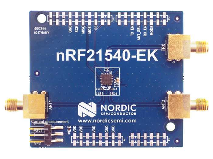
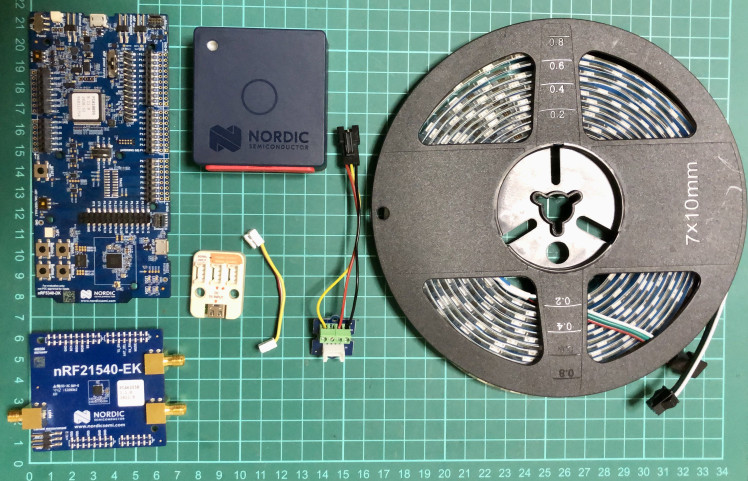
For the lighting system, we are using Nordic Semiconductor's nRF21540 EK, an Arduino Uno Rev3 compatible shield with nRF21540 RF FEM, that is used together with the nRF5340 DK, a development kit for the nRF5340 System-on-Chip (SoC). The nRF21540 RF front-end module(FEM) is a range extender offering enhanced link robustness with an integrated power amplifier (PA) and low noise amplifier (LNA).
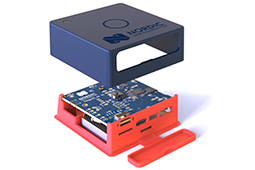
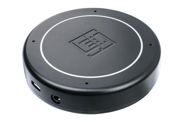
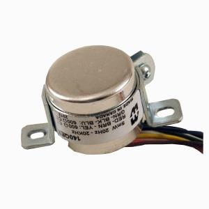
To control the lighting system, we are using Nordic Semiconductor's Thingy:53, an easy-to-use IoT prototyping platform that is built around the nRF5340 SoC. The lighting system is powered using an external 5000mAh/5V power bank to supply power to an M5Stack 300-pixels RGB LED strip based on the SK6812 chip.
Setup Development Environment
For the development work, I am using macOS but the setup process is similar for all platforms. First, we need to download nRF connect for Desktop from here:
https://www.nordicsemi.com/Software-and-tools/Development-Tools/nRF-Connect-for-desktop/Download.
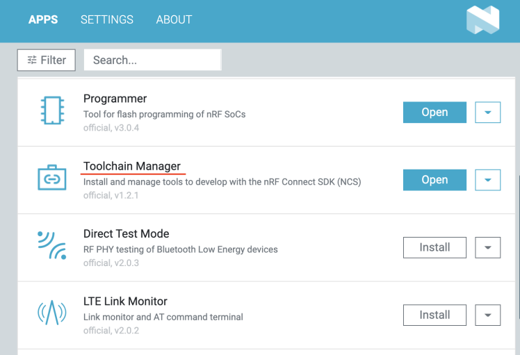
The nRF Connect for Desktop is a cross-platform tool that enables testing and development with nRF21540 EK, nRF5340 DK, and Thingy:53. Please follow the installation guide in the link above. When the installation is completed, open the app and click on the Toolchain Manager and choose nRF Connect SDK v2.1.2.
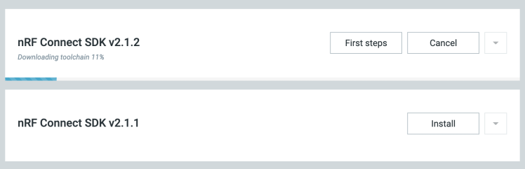
By default, the SDK is installed in the /opt/nordic/ncs directory in macOS. After installation, click on the Open Terminal which opens up a command line terminal with all environment variables initialized to get started quickly with the development.

Application development
We are using nRF21540 EK + nRF5340 DK as a central device which is physically connected to the RGB LED strip and the Thingy:53 is used as a peripheral device which is connected to the central device over BLE connection to control the lights. The central and peripheral device application codes are based on the nRF Connect SDK examples.
We can add the following config in the child_image/hci_rpmsg/boards/thingy53_nrf5340_cpunet.conf (peripheral) and child_image/hci_rpmsg.conf (central) files to increase or decrease the RF TX range strength.
- CONFIG_MPSL_FEM_NRF21540_TX_GAIN_DB=10
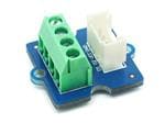
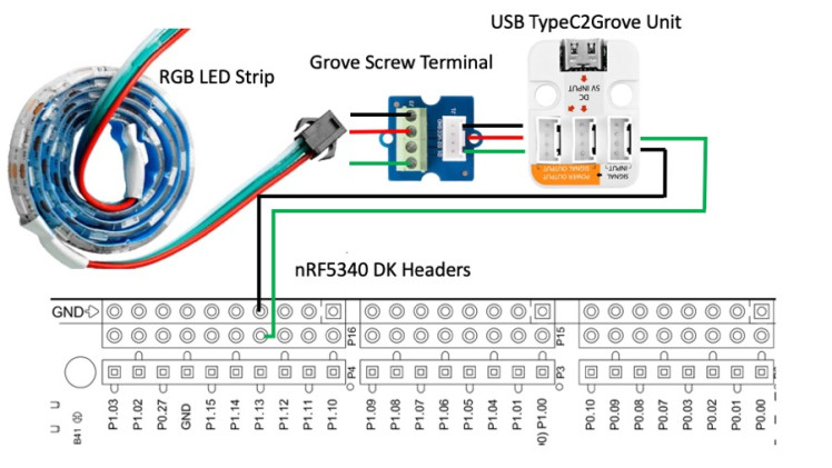
The nRF5340 DK digital pin P1.13 and GND pins are connected to the RGB LED strip DATA and GND pins respectively. Since nRF5340 DK cannot provide the required current to the RGB LED strip, it receives the power from a 5V external power supply using a USB TypeC2Grove Unit that combines the DATA/GND with a 5V power supply. Below are the schematics for the physical connections to the RGB LED strip and the nRF5340 DK pin headers.
To set up the pin configuration to drive neopixel we need to add an overlay file (boards/nrf5340dk_nrf5340_cpuapp.overlay) as given below. Although the overlay is based on the WS2812 neopixel chip, it can be used for the SK6812 chip.
- #include <zephyr/dt-bindings/led/led.h>
- #define SPI_FREQ 4000000
- #define ZERO_FRAME 0x40
- #define ONE_FRAME 0x70
- #define NUM_LEDS 300
- &arduino_spi { /* MOSI on D11 / P1.13 */
- compatible = "nordic,nrf-spim";
- led_strip: ws2812@0 {
- compatible = "worldsemi,ws2812-spi";
- /* SPI */
- reg = <0>; /* ignored, but necessary for SPI bindings */
- spi-max-frequency = <SPI_FREQ>;
- /* WS2812 or similar */
- chain-length = <NUM_LEDS>;
- color-mapping = <LED_COLOR_ID_GREEN
- LED_COLOR_ID_RED
- LED_COLOR_ID_BLUE>;
- spi-one-frame = <ONE_FRAME>;
- spi-zero-frame = <ZERO_FRAME>;
- };
- };
- / {
- aliases {
- led-strip = &led_strip;
- };
- };
To make the lighting eye soothing and draw less current we have applied gamma correction to the RGB LED colorspace.
Build and flash the firmware
First, open the terminal using the Toolchain manager as described in the Setup Development Environment section.
- $ git clone https://github.com/metanav/long_range_lighting_system_using_nRF21540.git
For nRF21540 EK + nRF5340 DK, connect it to the computer using a USB cable and execute the command below to build and flash the firmware.
- $ cd long_range_lighting_system_using_nRF21540/nrf5340dk_nrf21540ek_fem_led_strip_central
- $ west build -b nrf5340dk_nrf5340_cpuapp -- -DSHIELD=nrf21540_ek
- -Dhci_rpmsg_SHIELD=nrf21540_ek
- $ west flash
For Thingy:53, execute the command below to build the firmware.
- $ west build -b thingy53_nrf5340_cpuapp
There are many ways to flash firmware to the Nordic Thingy:53. We are using a J-Link Edu Mini, an external debug probe, to flash the firmware by following the steps below.
- Open the connector cover on the side of the Nordic Thingy:53 (see the image below).
- Use a JTAG cable to connect the Nordic Thingy:53 to the debug out port on a 10-pin external debug probe.
- Power on the Nordic Thingy:53; move the power switch SW1 to the ON position.
- Connect the external debug probe to the computer with a micro-USB cable.
After setting up the hardware, execute the command below.
- $ west flash
Running Application
On powering up both devices, the central device (nRF21540 EK + nRF5340 DK) tries to discover and connect to the peripheral devices (Thingy:53) automatically. The peripheral device's onboard RGB LED blinks red when it is not bound to the central device. Once it is connected to the central device, the LED starts blinking green and yellow alternatively. Also, when the central device is connected to the peripheral device, the onboard green LED is lit. After a successful connection, we can click the button on the peripheral device to control the RGB LED strip connected to the central device in the cyclic order.
Slow scrolling -> Fast scrolling -> Turn off -> Turn On
Current Measurement on the central device
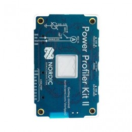
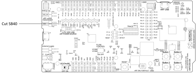
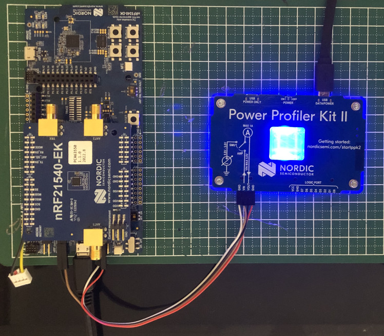
We will use the Power Profiler Kit II (PPK2) which can measure and optionally supply currents from sub-uA and as high as 1A on all Nordic DKs. To measure current on the nRF5340 DK equipped with nRF21540 EK, we need to put P22 in series with the load by cutting the PCB track shorting solder bridge SB40 as shown below in the image. The suggested configurations split the power domains for the nRF5340 SoC and the rest of the DK.
Connect the PPK2 to the DK with a 4-pin measurement cable using the following pins:
- PPK2 VIN to P22 VDD_nRF'
- PPK2 VOUT to P22 VDD_nRF
- PPK2 GND to P21
Connect the DK to a computer using a micro-USB cable.
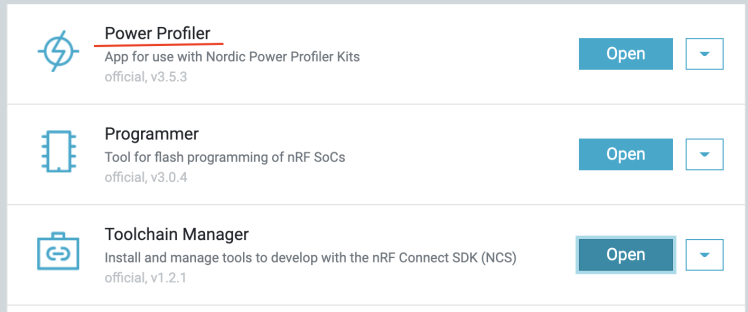
Start the Power Profiler app using the nRF Connect for Desktop app.
Select the device PPK2 in the left panel as shown in the image below.

Select Ampere meter as the mode.
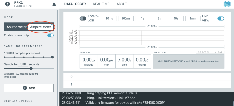
Click on the Start button (see in the image above) to begin sampling the current measurements as shown in the live view below. The average current consumption is around 2 mA with peaks at near 16 mA.
Live Demo
The initial setup testing is done to make sure everything works as expected.
For long-range testing, the peripheral device is moved to a far distance. To comply with the country's RF laws the RF TX strength is kept at 10dB which is the default value.
Conclusion
The system has been tested successfully from 500 meters line-of-sight distance and can be extended possibly up to 800 meters with increased RF signal strength and favorable environmental conditions. It is important to keep the line of sight with the correct orientation of the boards to achieve long-range functionality.
Schematics, diagrams and documents
Code
Credits
Related products


Leave your feedback...