
Remote Access And Control Controllino With Adafruit Io Mqtt

Made by Ron / Communication / Displays / IoT
About the project
Use the Adafruit IO MQTT to remotely access and control Controllino MEGA PLC. Program with Visuino - Quick and Easy!
Project info
Difficulty: Moderate
Estimated time: 1 hour
License: GNU General Public License, version 3 or later (GPL3+)
Items used in this project

Software apps and online services
Story
Arduino is a very popular platform for Makers. Although it is a very capable controller, it has not found very good adoption in the industry however, due to the lack of robust, certified, industry ready Arduino based PLC modules. Controllino changed all this. Controllino is the first open source industry ready Programmable Logic Controller (PLC). It comes in 3 versions - MINI, MAXI, and MEGA. All versions come with built-in RTC, ready relay control outputs, and the MINI and MAXI in addition have built-in RS485 and Ethernet.
All this makes them a very attractive and flexible low cost PLC choice.
Visuino fully supports Controllino, and the combination of powerful, industry ready PLC and the easy graphical development of Visuino, makes it possible to create and deploy complex designs very rapidly.
Recently, I added MQTT support in Visuino, and I started planning on writing MQTT Tutorial. The plan was to use ESP8266, or maybe even GSM Shield. In the following days, however, few people asked how to use MQTT with Controllino. I already had plans for Controllino tutorials, so I decided to do it with Controllino instead.
In this Tutorial I will use the Adafruit IO as MQTT Server. You can create free account on the Adafruit site, and use it to login in to the Adafruit IO.
For this Tutorial to work, you need to create the Adafruit IO account, then follow this Adafruit IO Tutorial to create one stream, with 2 feeds (MQTT Topics) named "onoff" and "photocell" as described in the tutorial.
The only change I would recommend is on the "Create your first two feeds" step for the "photocell" to use max value of 100 instead of 1024 as shown in the tutorial.
Step 1: Components
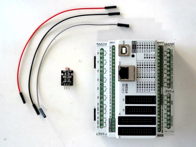
- One Controllino MEGA PLC
- One Photoresistor Sensor module I got from this cheap 37 sensors set
- 3 Female-Female jumper wires
1 / 5 • Picture 1

Picture 1

Picture 2

Picture 3

Picture 4

Picture 5
- Connect Ground(Black wire), Power(Red wire), and Signal(Gray wire) to the Photoresistor Module (Picture 1)
- Connect the other end of the Power wire(Red wire) to the 5V power pin of the Controllino MEGA (Picture 2)
- Connect the other end of the Ground wire(Black wire) to the Ground pin of the Controllino MEGA (Picture 3)
- Connect the other end of the Signal wire(Gray wire) to the Analog pin 0 of the Controllino MEGA (Pictures 4 and 5)
- You can see the Controllino MEGA Pinout here - http://controllino.biz/wp-content/uploads/2016/02/CONTROLLINO-MEGA-PINOUT-09-02-16.pdf
1 / 2 • Picture 1

Picture 1

Picture 2
To start programming the Arduino, you will need to have the Arduino IDE installed from here: http://www.arduino.cc/.
Make sure that you install 1.6.7 or higher, otherwise this Tutorial will not work!
Once you have the Arduino IDE installed, you will need to install the Controllino board support, and the Controllino libraries. Here is instruction on how to do this.
The Visuino: https://www.visuino.com also needs to be installed.
- Click on the "Tools" button on the Arduino component (Picture 1) in Visuino When the dialog appears, select Controllino MEGA as shown in Picture 2
- Start Visuino as shown in the first picture
1 / 5 • Picture 1

Picture 1

Picture 2

Picture 3

Picture 4

Picture 5
First we need to assign MAC address to the Ethernet controller, and add a TCP/IP Client socket so we can connect to the Adafruit IO trough MQTT:
- In the Object Inspector expand the "Modules" property, then its "Ethernet" sub-property, and set the value of the "Mac Address" sub-property to some MAC address. I used "DE-AD-BE-EF-FE-ED", but you should probably use a MAC generator.
- In the Object Inspector, click on the "..." button next to the value of the "Sockets" sub property of the "Ethernet" property (Picture 2)
- In the Sockets editor select “TCP/IP Client”, and then click on the "+" button (Picture 2) to add one (Picture 3)
- In the Object Inspector set the value of the "Host" property to "io.adafruit.com" (Picture 4)
- In the Object Inspector set the value of the "Port" property to "1883" (Picture 4)
- Close the "Sockets" dialog
1 / 5 • Picture 1

Picture 1

Picture 2

Picture 3

Picture 4

Picture 5
Next we need to add and connect MQTT component:
- Type "mqtt" in the Filter box of the Component Toolbox then select the "MQTT Client" component (Picture 1), and drop it in the design area
- Connect the "Out" output pin of the "Modules.Ethernet.Sockets.TCP Client1" element of the "Controllino MEGA" component to the "In" input pin of the MQTTClient1 component (Picture 2)
- Connect the "Out" output pin of the MQTTClient1 component to the "In" input pin of the "Modules.Ethernet.Sockets.TCP Client1" element of the "Controllino MEGA" component (Picture 3)
- Connect the "Connected" output pin of the "Modules.Ethernet.Sockets.TCP Client1" element of the "Controllino MEGA" component to the "Connected" input pin of the MQTTClient1 component (Picture 2)
- Connect the "Disconnect" output pin of the MQTTClient1 component to the "Disconnect" input pin of the "Modules.Ethernet.Sockets.TCP Client1" element of the "Controllino MEGA" component (Picture 3)
1 / 3 • Picture 1

Picture 1

Picture 2

Picture 3
We need to specify the User Name and Password(Key) for the MQTT. We will copy them from the Adafruit IO account, so the Controllino can connect to it:
- Follow the instructions at "Where to find your adafruit.io key" from this Adafruit tutorial to find your Adafruit.IO Key, and copy it (Picture 1)
- In the Object Inspector paste the Key as a value of the "Password" property (Picture 2)
- In the object inspector set the value of the "User Name" property to your Adafruit User Name (Picture 3)
1 / 4 • Picture 1

Picture 1

Picture 2

Picture 3

Picture 4
Next we need to add 2 Topics to the MQTT Client for the 2 Adafruit.IO feeds - photocell and onoff:
- Click on the "Tools" button of the MQTTClient1component (Picture 1)
- In the "Topics" editor select the “Text” element, and then click 2 times on the "+" button on the left (Picture 2) to add 2 Text Topics (Picture 3)
- Select the first Topic element (Picture 3)
- In the Object Inspector for the value of the "Topic" property, enter your Adafruit User Name, followed by the "/feeds/onoff" (Picture 3)
- Select the second Topic element (Picture 4)
- In the Object Inspector for the value of the "Topic" property, enter your Adafruit User Name, followed by the "/feeds/photocell" (Picture 4)
- Close the "Characteristics" editor
1 / 5 • Picture 1

Picture 1

Picture 2

Picture 3

Picture 4

Picture 5
The Adafruit IO MQTT sends "ON" and "OFF" strings through the "onoff" feed. We need to convert it to digital signal. To do this we will use a "Compare Text Value" component to compare the text with "ON":
- Type "compare" in the Filter box of the Component Toolbox then select the "Compare Text Value" component (Picture 1), and drop it in the design area
- In the Object Inspector, set the value of the "Value" property of the CompareTextValue1 component to "ON" (Picture 2)
- Connect the "Out" pin of the "Topics.Text Topic1" element of the MQTTClient1 (Picture 3) to the "In" pin of the CompareTextValue1 (Picture 4)
- Connect the "Out" output pin of the CompareTextValue1 to the "Digital" input pin of the "Digital[ 2 ]" channel of the Controllino MEGA component (Picture 5)
1 / 4 • Picture 1

Picture 1

Picture 2

Picture 3

Picture 4
We don't want to send data through MQTT all the time. This can overwhelm the network. Instead we will take a snapshot of the data once a second, with an "Analog Snapshot" component:
- Type "snapshot" in the Filter box of the Component Toolbox then select the "Analog Snapshot" component (Picture 1), and drop it in the design area
- Connect the "Out" output pin of the AnalogSnapshot1 component to the "In" input pin of the "Topics.Text Topic2" element of the MQTTClient1 component (Picture 2)
- Type "clock" in the Filter box of the Component Toolbox then select the "Clock Generator" component (Picture 3), and drop it in the design area
- Connect the "Out" output pin of the ClockGenerator1 component to the "Snapshot" input pin of the AnalogSnapshot1 component (Picture 4)
1 / 5 • Picture 1

Picture 1

Picture 2

Picture 3

Picture 4

Picture 5
The Analog 0 channel provides data between 0.0 and 1.0. It is better to convert it to values between 0 and 100 for the Adafruit.IO, so we will multiply it by 100:
- Type "multip" in the Filter box of the Component Toolbox then select the "Multiply By Value" component (Picture 1), and drop it in the design area
- In the Object Inspector, set the value of the "Value" property to "100" (Picture 2)
- Connect the "Out" output pin of the MutiplyByValue1 component to the "In" input pin of the AnalogSnapshot1 component (Picture 3)
- Connect the "In" input pin of the MutiplyByValue1 component (Picture 4) to the "Out" output pin of the "Analog[ 0 ]" channel of the Controllino MEGA component (Picture 5)
1 / 2 • Picture 1

Picture 1

Picture 2
- In Visuino, Press F9 or click on the button shown on Picture 1 to generate the Arduino code, and open the Arduino IDE
- Connect the Controllino MEGA with USB cable to the computer
- Select the board type as "Controllino MEGA" and serial port
- In the Arduino IDE, click on the Upload button, to compile and upload the code (Picture 2)
1 / 3 • Picture 1

Picture 1

Picture 2

Picture 3
Congratulations! You have completed the project.
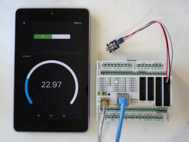
From a computer or a mobile device start a web browser, login to your Adafruit IO account, and then navigate to open the stream that you have created following this Adafruit IO tutorial (Picture 1)
On the Video you can see the Controllino MEGA's LED being controlled, and the value of the Photoresistor displayed through a web browser on a PC and Android Tablet..
As shown in the Video, you can control the LED on the Digital 2 pin with the On/Off Switch, and monitor the values from the Photoresistor on the Gauge.
On Picture 2 you can see the connected Controllino MEGA controlled by an Android Tablet.
On Picture 3 you can see the complete Visuino diagram.
Also attached is the Visuino project, that I created for this Tutorial. You can download and open it in Visuino: https://www.visuino.com
Credits
Related products


Leave your feedback...