
Rc Four Wheel Ground Rover

Made by vishnumaiea / Automotive / Robotics / Sports / Vehicles
About the project
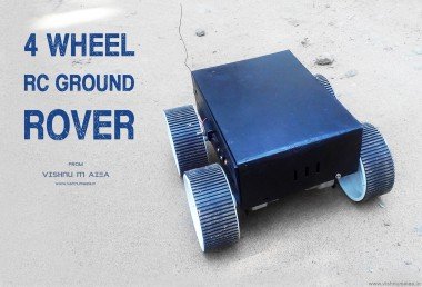
This is an RF controlled four-wheel ground rover built from scratch. The RF remote controller has 100 m range in open space.
Project info
Items used in this project
Hardware components


View all
Hand tools and fabrication machines
Story
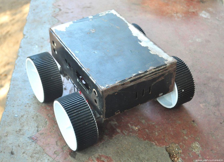
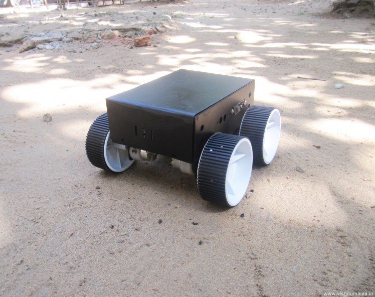
This is a "Monolith on wheels" (thanks to Stanley Kubrick :D )
It was one of my dream to build a remote controlled ground rover ever since I started tinkering with electronics, becasue wireless things have always fascinated me. I hadn't got enough time and money to build one until for my college project. So I built a four wheel rover for my final year project. In this tutorial I'll explain how I used an old amplifier's enclosure to build the rover from scratch and how to make the radio controller.
This is a four wheel ground rover, with four separate driving motors. The motor driver circuit is based around L298N, and the RF control is based on HT12E and HT12D pair from Holtek semiconductor. It doesn't use Arduino or any other microcontrollers. The version I made uses cheap 433 MHz ISM band ASK transmitter and receiver pair for wireless operation. The rover is controlled by four push buttons and the driving method used is differential drive. The controller has a range of about 100 m in open space. Let's start building now.
(All images are in high resolutions. Open them in new tab for high res.)
Step 1: Parts and Tools Required
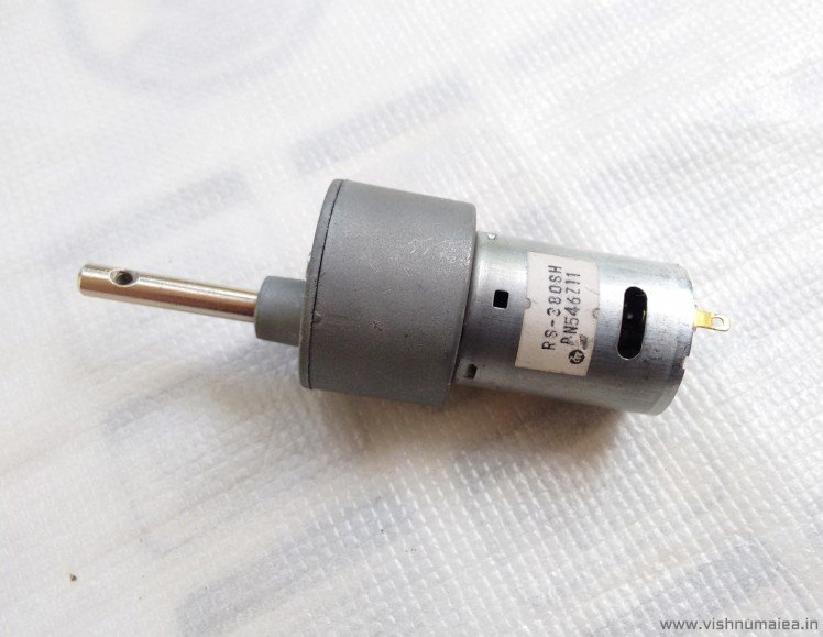
Johnson Geared Motor
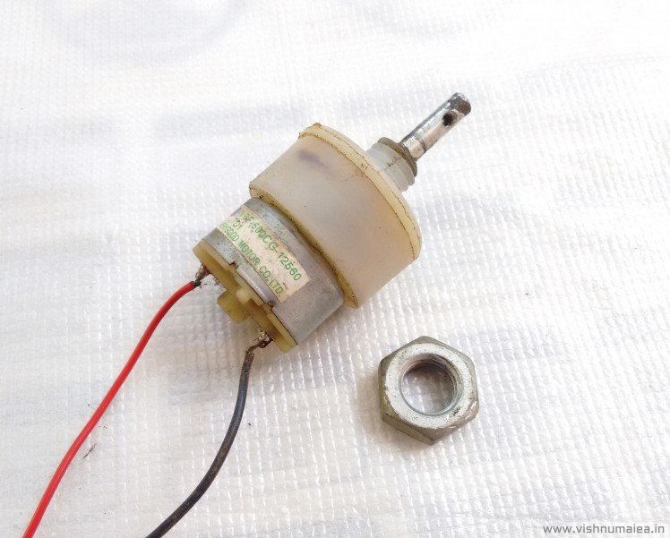
DC Geared Motor
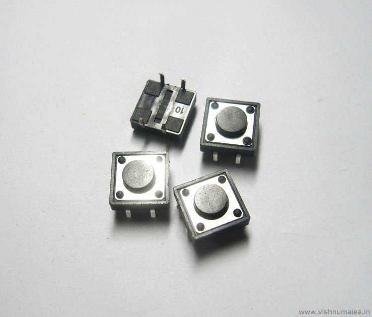
Push Buttons
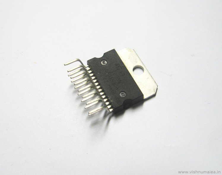
L298 IC/Module
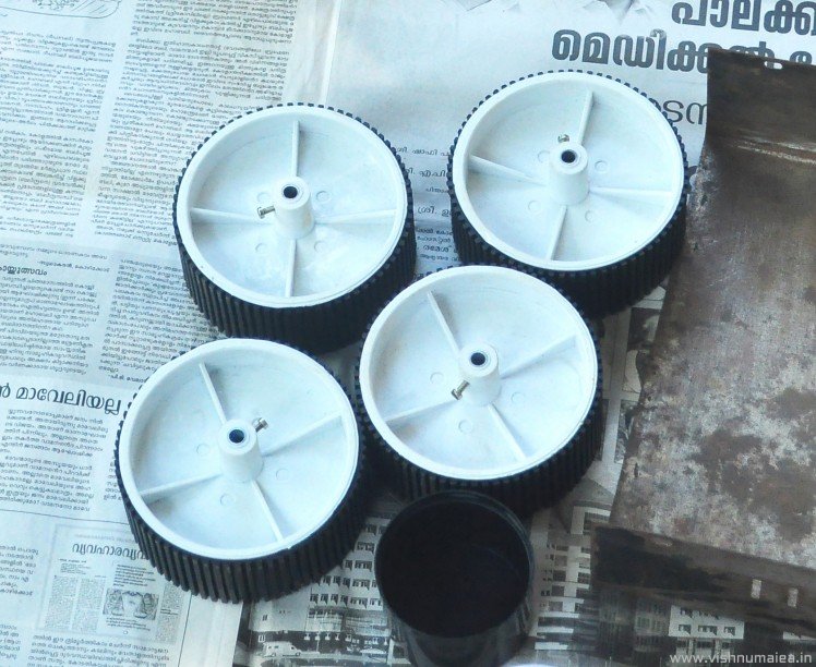
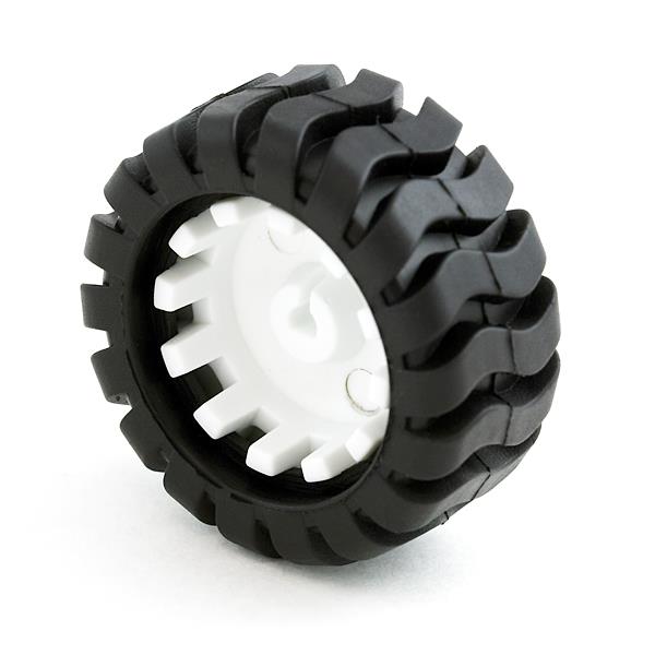
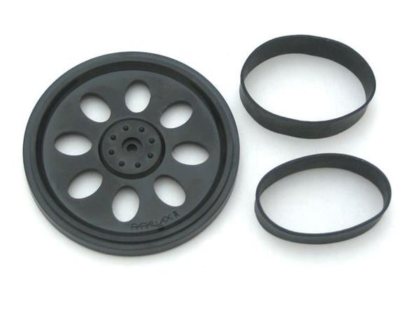
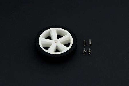
10 cm dia x 4 cm width x 6 mm bore Wheels
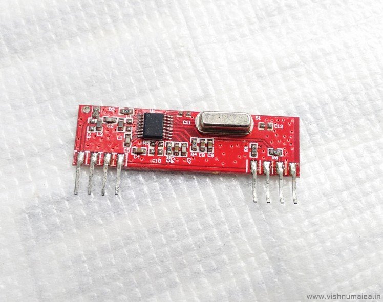
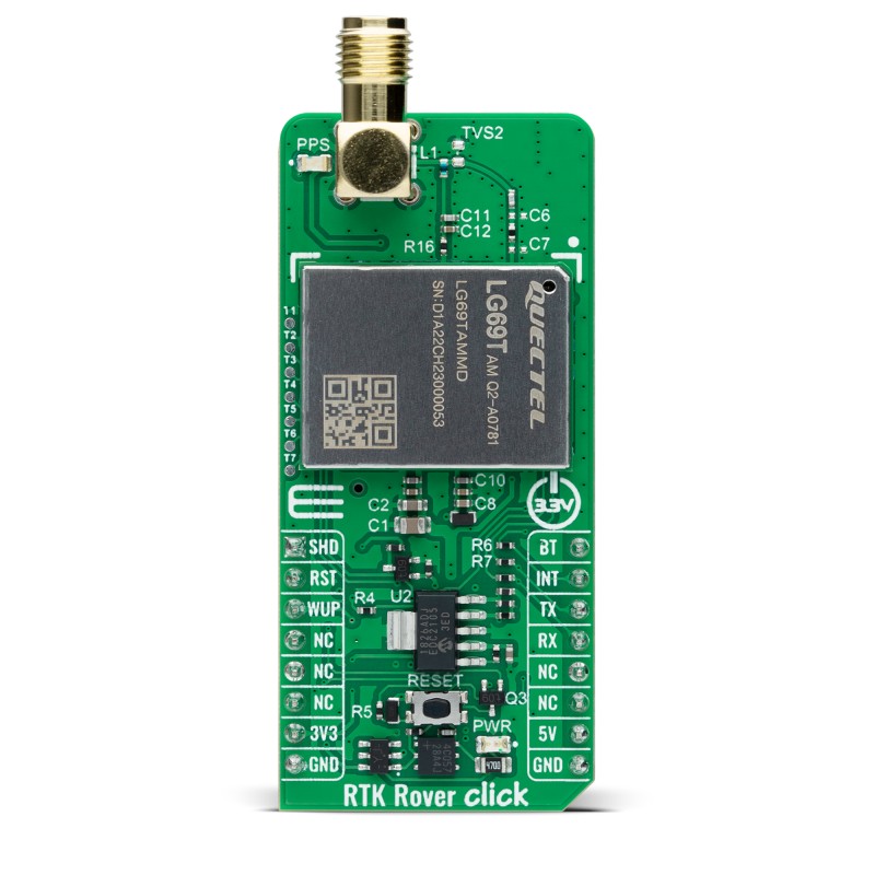
433MHz RF Receiver
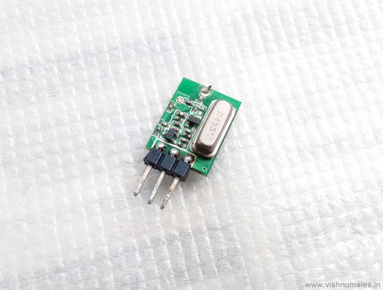
433MHz RF Transmitter
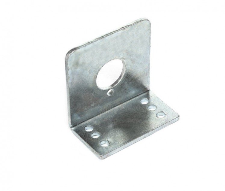
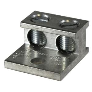
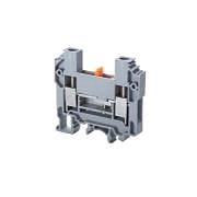
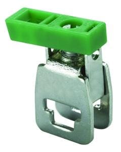
Motor Clamp
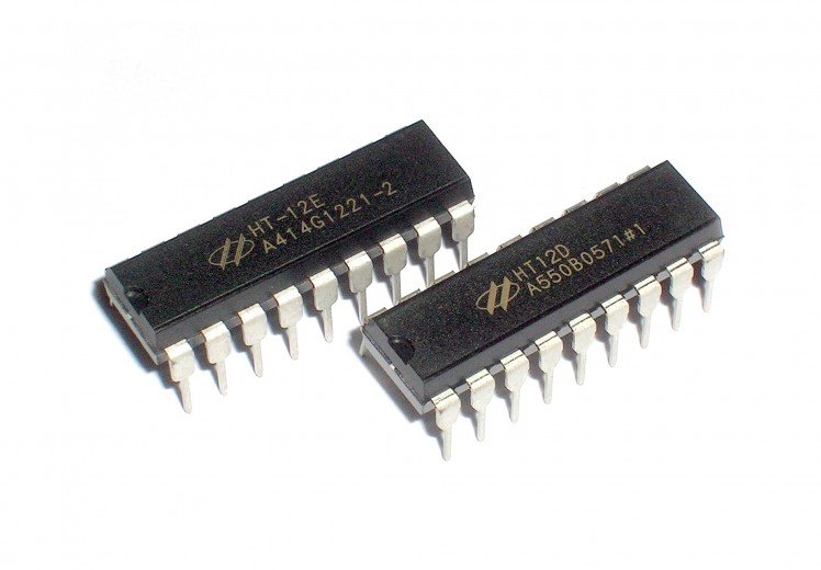
HT12E and HT12D

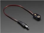
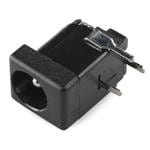
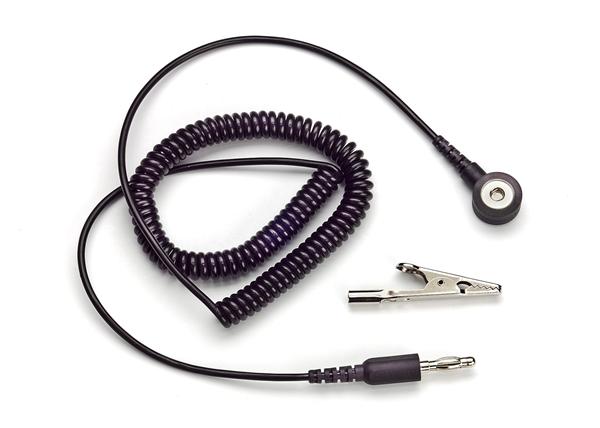
SPDT Switch and DC Jack
Other parts required are LEDs, wires, IC sockets, switches, sand papers, and other tools. Parts such as motors, wheels, clamps etc can be selected as per your requirements.
Step 2: Motor Driver Schematic
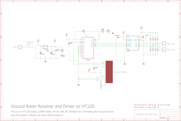
Motor driver schematic
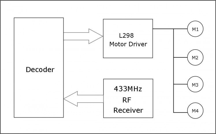
Motor driver block diagram
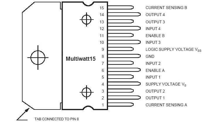
L298 pinout
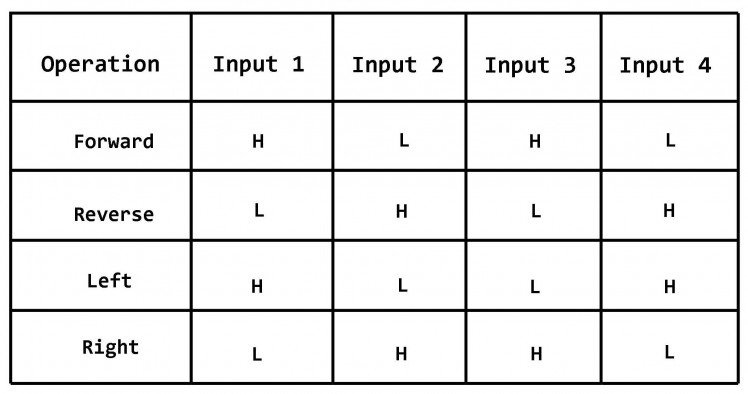
Motor driver logic table

Motor driver connection diagram
The HT12D is a 12-bit decoder which is a serial input-parallel output decoder. The input pin of the HT12D will be connected to a receiver which has a serial output. Among the 12-bits, 8 bits are address bits and the HT12D will decode the input if only if the incoming data matches its current address. This is useful if you want to operate many devices in the same frequency. You could use an 8 pin DIP switch for setting the address value. But I soldered them directly to GND which yields the address 00000000. The HT12D is here operated at 5V and the Rosc value is 51 KΩ. The value of the resistor is important as changing it might cause problems with decoding.
The output of the 433MHz receiver is connected to the input of HT12D, and the four outputs are connected to the L298 2A dual H-bridge driver. The driver needs a heat sink for proper heat dissipation as it can become very hot.
When I press the Left button on the remote, I want M1 and M2 to run in a direction opposite to that of M3 and M4 and vice versa for Right operation. For Forward operation, all the motors will have to run in the same direction. This is called differential drive and is what used in battle tanks. Therefore we just need not only one pin to control but four at the same time. This can not be achieved by SPST push buttons which I've got, unless you have some SPDT switches or a joystick. You'll understand this by looking at the logic table shown above. The required logic is achieved at the transmitter end in the next step.
The whole setup is powered by two 6V, 5Ah Lead-Acid batteries in series configuration. This way we'll have plenty of room to place the batteries inside the chassis. But it'll be better if you can find Li-Po batteries in the range of 12V. A DC barrel jack is used to connect the Pb-Acid batteries to external charger. 5V for HT12D is generated using a 7805 regulator.
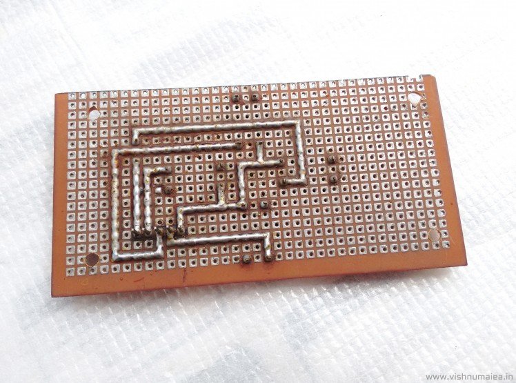
Step 3: Building the Motor Driver
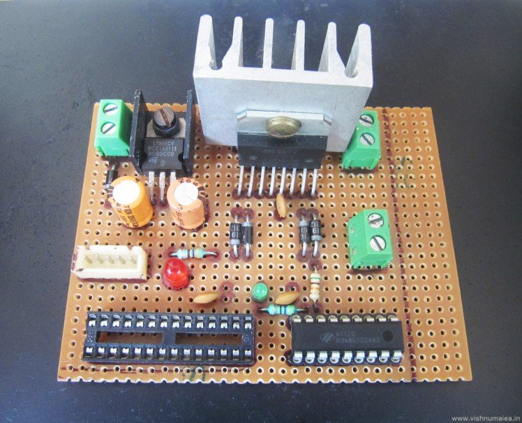
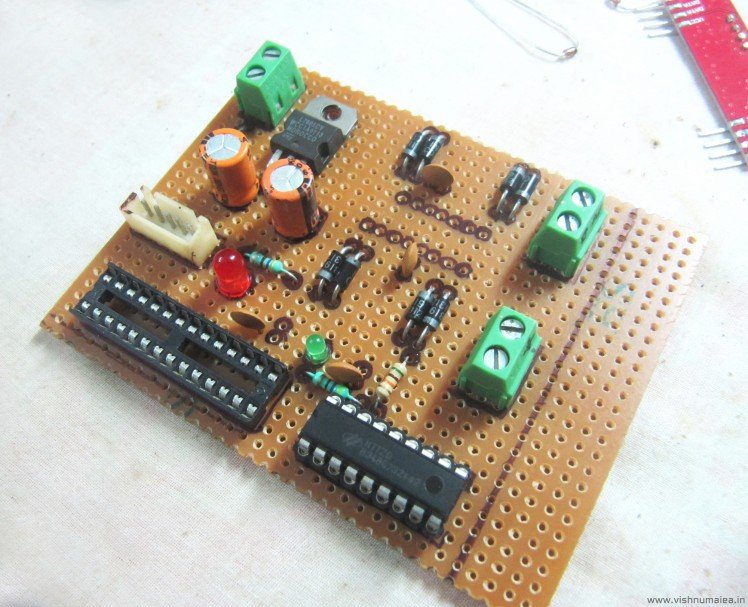
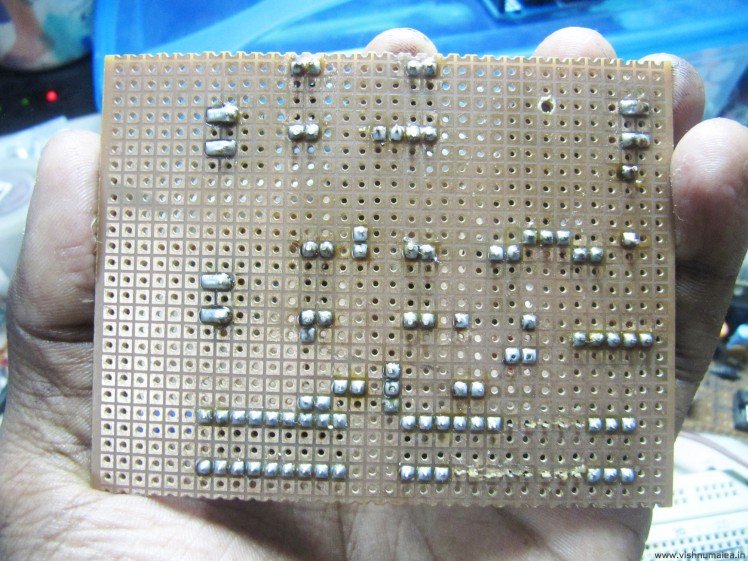
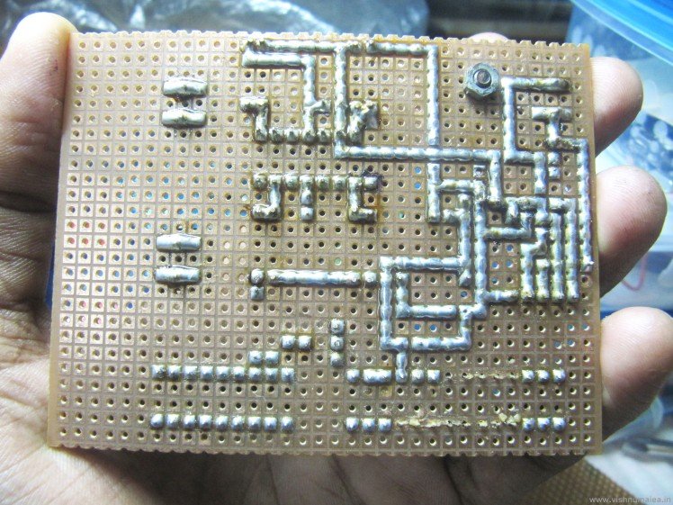
I used a perfboard for soldering all the components. First place the components in a way it's easier to solder them without using many jumpers. This is a matter of experience. Once the placement is satisfactory, solder the legs and cut away the excess parts. Now it's time for routing. You might have used auto-router feature on many PCB design softwares. You're the router here. Use your logic for best routing with minimal use of jumpers.
I used an IC socket for the RF receiver instead of directly soldering it, because I can reuse it later. The whole board is modular so that I can disassemble them easily if required later. Being modular is one of my penchants.
Step 4: RF Remote Controller Schematic
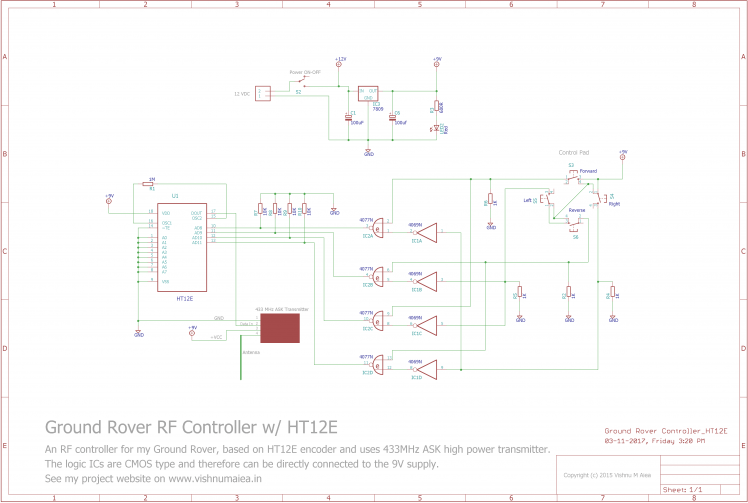
RF Controller Scheamtic
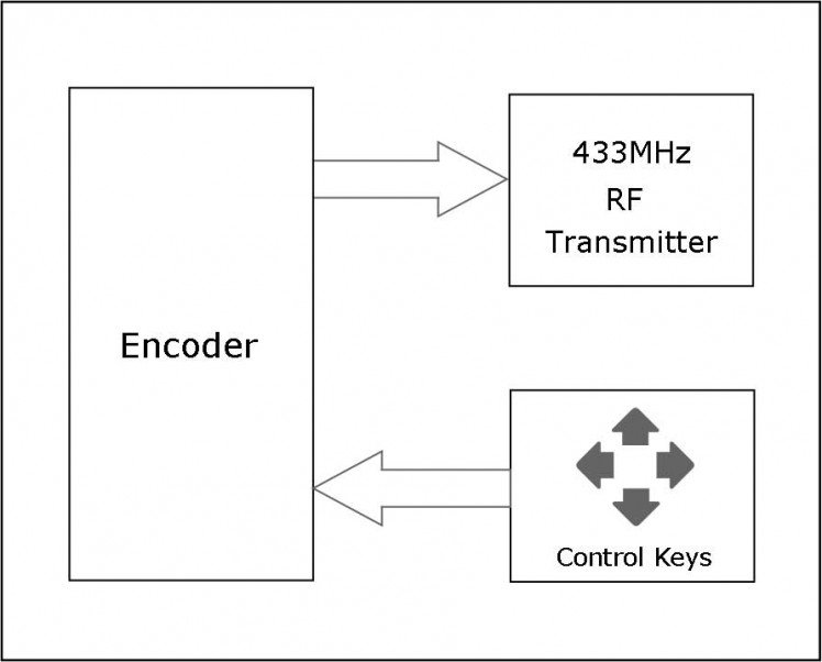
RF Controller Block Diagram
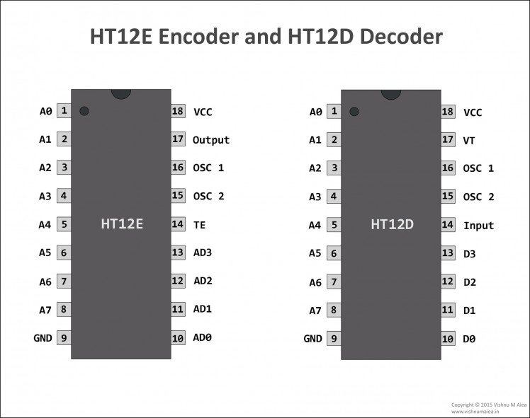
Pinouts of HT12E and HT12D
This is a 4 channel RF remote controller for the rover. The remote controller is based on HT12E and HT12D, 2^12 series encoder-decoder pair from Holtek semiconductor. The RF communication is made possible by 433MHz ASK transmitter-receiver pair.
The HT12E is a 12-bit encoder and basically a parallel input-serial output encoder. Out of 12 bits, 8-bits are address bits which can be utilized for controlling multiple receivers. The pins A0-A7 are the address input pins. The oscillator frequency should be 3 KHz for 5V operation. Then Rosc value will be 1.1 MΩ for 5V. We're suing 9V battery, and therefore the Rosc value is 1 MΩ. Refer to the datasheet to determine exact oscillator frequency and resistor to be used for a specific voltage range. AD0-AD3 are the control bit inputs. These inputs will control the D0-D3 outputs of the HT12D decoder. You can connect the output of the HT12E to any transmitter module that accepts serial data. In this case, we connect the output to the input pin of the 433MHz transmitter.
We have four motors to control remotely, of which each two are connected parallel for differential drive as seen in the previous block diagram. I wanted to control the motors for differential drive with four SPST push-buttons which are commonly available. But there's a problem. We can not control (or enable) multiple channels of the HT12E encoder with just SPST push-buttons. This is where the logic gates come into play. One 4069 CMOS NOR and one 4077 NAND form the logic driver. For each press of the push-buttons, the logic combination generates required signals on multiple input pins of the encoder (this was an intuitive solution, rather than something decided by experimentation, like a "light bulb!"). The output of these logic gates are connected to the inputs of the HT12E and sent serially through the transmitter. Upon receiving the signal, the HT12D will decode the signal and pull the the output pins accordingly which will then drive the L298N and the motors.
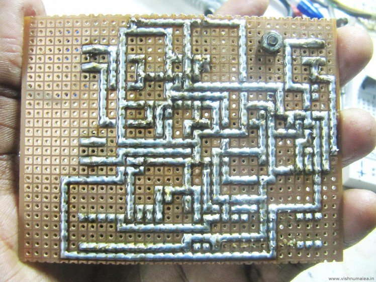
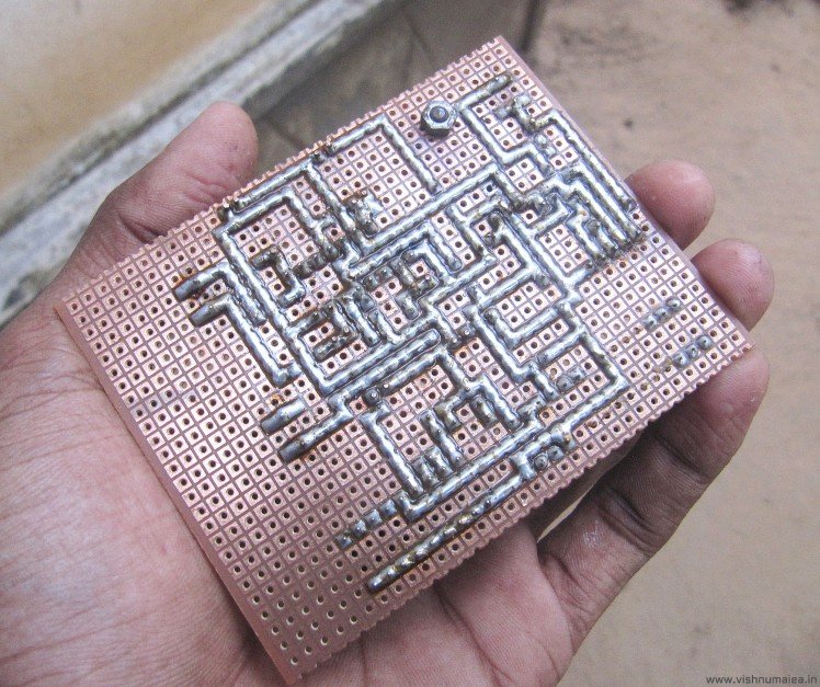
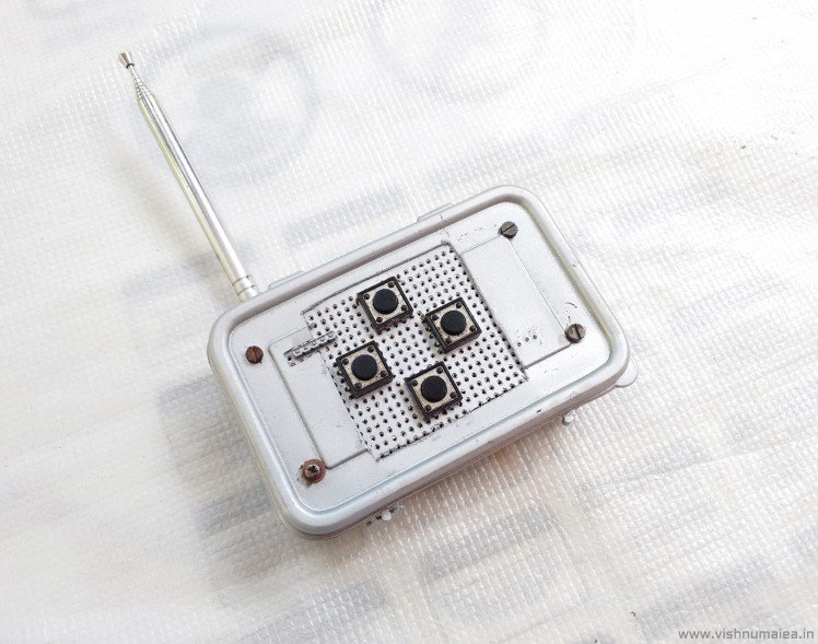
Step 5: Building the RF Remote Controller
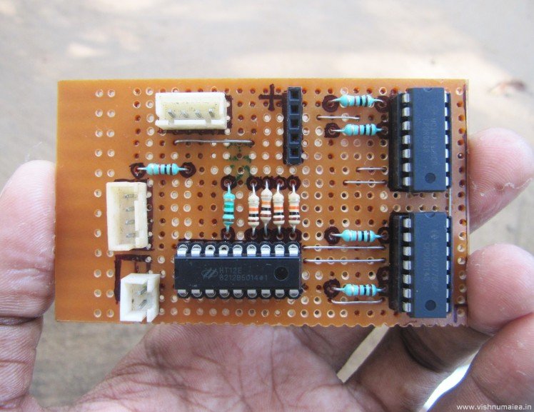

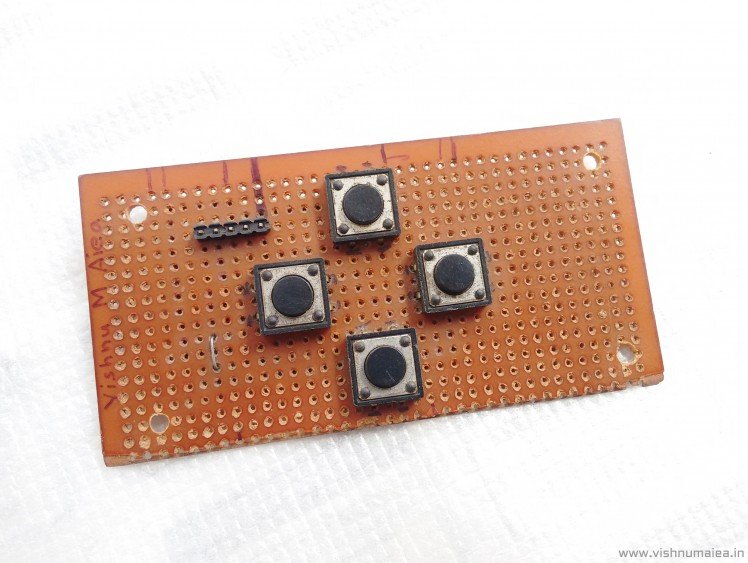
I used two separate perfboard pieces for the remote controller; one for the buttons and one for the logic circuit. All boards are fully modular and so can be detached without any desoldering. The antenna pin of the transmitter module is connected to an external telescopic antenna salvaged form an old radio. But you can use single piece of wire for it. The remote controller uses 9V battery directly.
Everything was crammed into a small plastic box I found in the junk box. Not the best way to make a remote controller, but it serves the purpose.
Step 6: Painting the Remote Controller

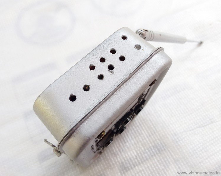
Vent for RF transmitter
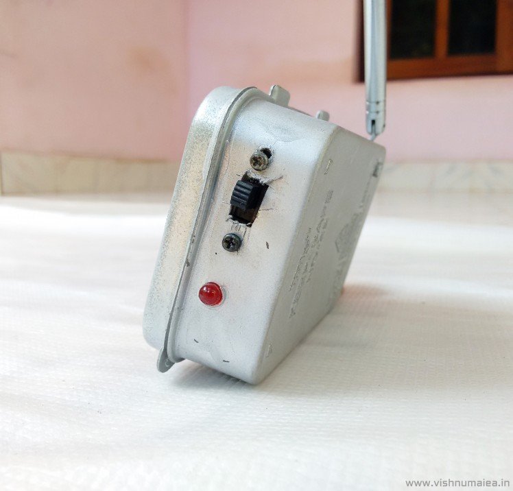
ON-OFF Switch, LED Indicator
Everything was packed inside with the push-buttons, DPDT switch, power on indicator LED and the antenna exposed. I drilled a few holes near the transmitter is placed because I found it gets heated up a little bit after prolonged operation. So the holes will provide some air flow.
It was a mistake to cut the large rectangular hole on the top instead of small four ones. I might have been thinking something else. I used metallic silver paint for finish.
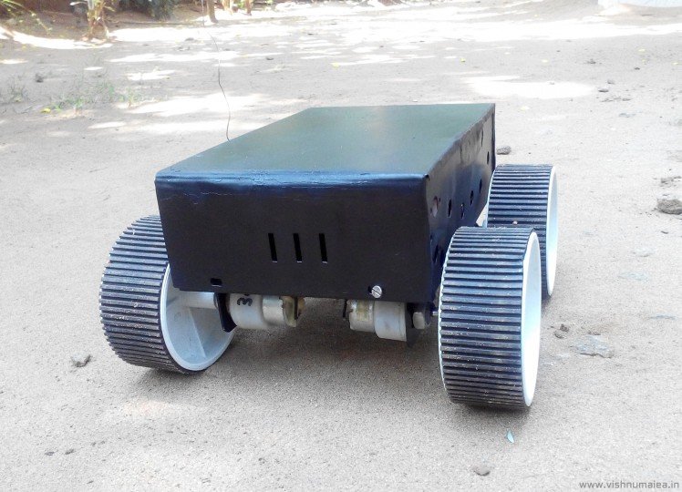
Step 7: Building the Chassis
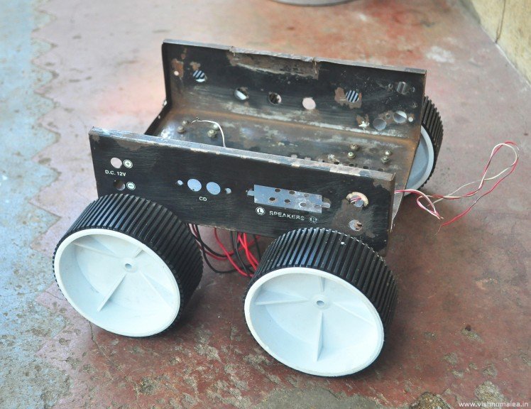
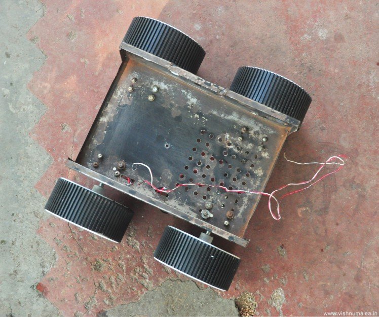

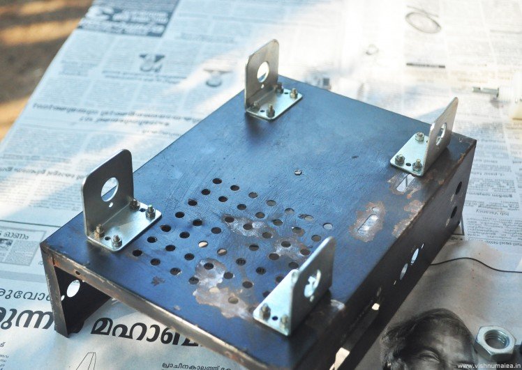
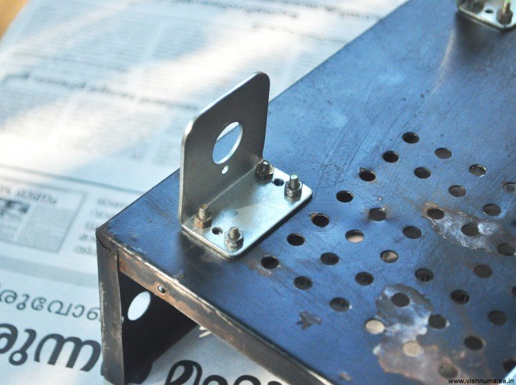
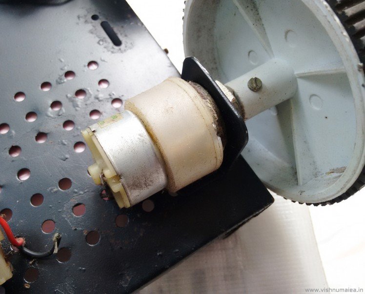
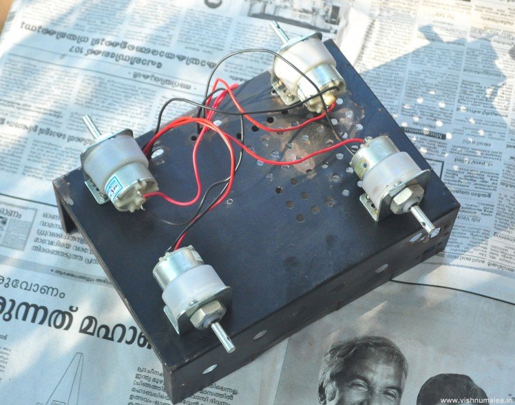
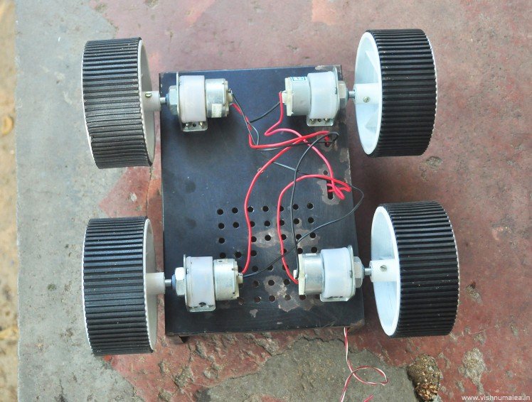
I used an old amplifier metal enclosure as the chassis of the rover. It had holes underneath, and had to widen some of them with a driller, which made fixing the motor clamps easy. You have to find something similar or to make one using sheet metal. The right angled motor clamps (or L clamps) have six screw holes each. The whole setup was not that sturdy as the sheet thickness was small, but enough for holding all the weight of batteries and all. The motors can be attached to the clamps by using the nuts provided with the DC geared motors. The motor shaft has threaded hole for attaching the wheels.
I used 300 RPM DC geared motors with plastic gear box. Plastic gearbox (gears are still metal) motors are cheaper than Johnson geared motors. But they'll wear out quicker and don't have that much torque. I suggest you to use Johnson geared motors with RPMs 500 or 600. 300 RPM isn't enough for a good speed.
Each motors must be soldered with a 100 nF ceramic capacitors to reduce contact sparks inside the motors. That'll ensure better life of the motors.
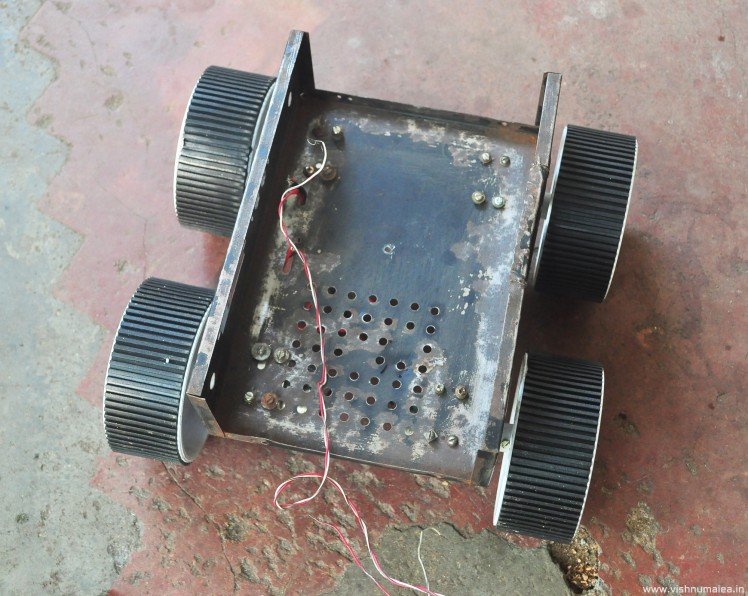
Step 8: Painting the Chassis
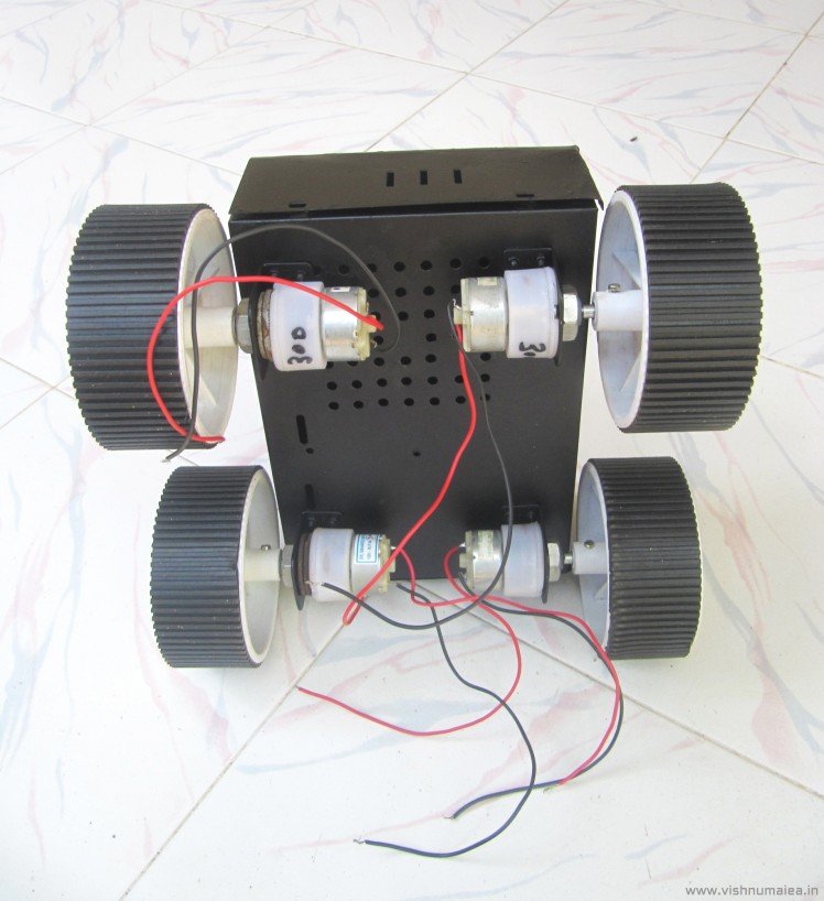

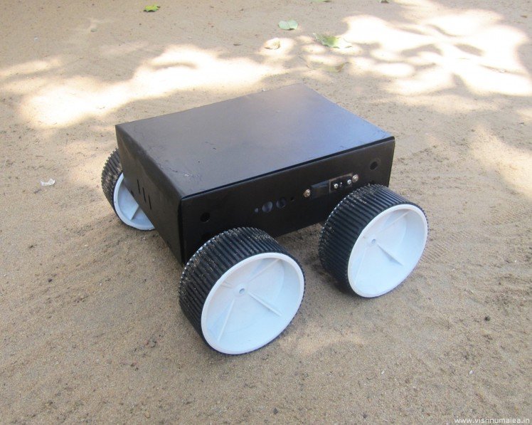
Painting is easy with spray paint cans. I used matte black for the whole chassis. You need to clean the metal body with sand paper and remove any old paint layers for better finish. Apply two coats for long life.
Step 9: Testing and Finishing

I was really excited to see that everything worked flawlessly at first time I tested it. I think that was the first time something like that happened.
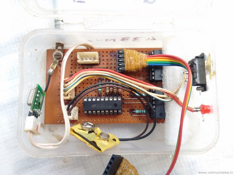
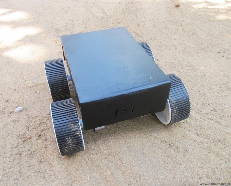
I used a tiffin box to hold the driver board inside. As everything is modular, assembling is easy. The antenna wire of the RF receiver was connected to a steel wire antenna outside of the chassis.
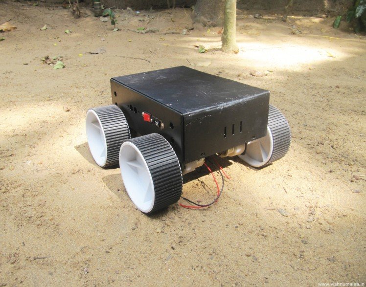
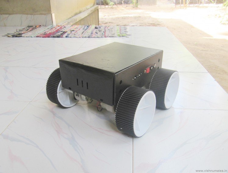
Everything just looked great when assembled, just as I expected.
Step 10: See It in Action
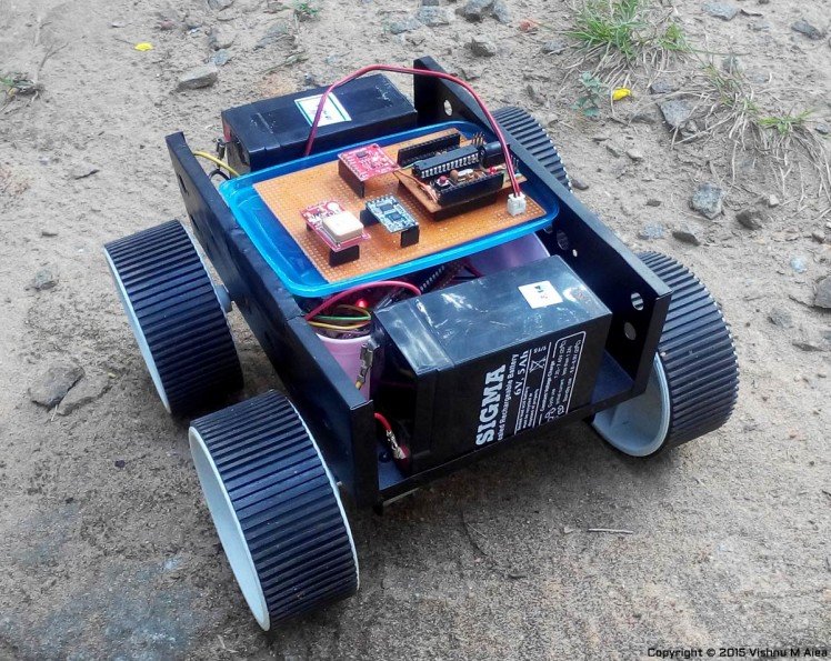
Above is when I used the rover to carry a GPS + Accelerometer module for another project. On the top board are the GPS, accelerometer, RF transceiver and a homemade Arduino. Beneath is the motor driver board. You can see how placed the Pb-Acid batteries there. There's enough space for them there despite having the tiffin box in the middle.
See the rover in action in the video. The video is a bit shaky as I shot it with my phone.
Step 11: Improvements
As I always say, there's always room for improvement. What I made is just a basic RC rover. It's not powerful enough to carry weights, dodge obstacles, and not fast either. The RF controller range is limited to around 100 metres in open space. You should try to resolve all these disadvantages when you build one; don't just replicate it, unless you're limited by availability of parts and tools. Here are some of my improvement suggestion for you.
- Use Johnson metal gearbox motors of 500 or 600 RPM for better speed-torque balance. They are really powerful and can output up to 12 Kg of torque at 12V. But you'll need a compatible motor driver, and batteries for high currents.
- Use a microcontroller for PWM control of the motor. This way you can control the speed of the rover. Will need a dedicated switch for the speed control at the remote controller end.
- Use a better and powerful radio transmitter and receiver pair for increased operating range.
- A strong chassis probably made from aluminium, along with spring shock absorbers.
- A rotating robotic platform for attaching robotic arms, cameras and other things. Can be made using a servo on the top of the chassis.
I plan to build a 6 wheel rover with all the feature mentioned above, and to be used as a general purpose rover platform. Hope you liked this project and learned something. Thanks for reading :)
Schematics, diagrams and documents
Credits
Related products


Leave your feedback...