
Raspberry Pi Home Automation Center

Made by madlab5 / Environmental Sensing / Home Automation / Sensors
About the project
I used a Raspberry Pi to monitor my smoke detectors, schedule sprinklers in my backyard, and operate cooling fans in my network cabinets.
Project info
Difficulty: Moderate
Platforms: Raspberry Pi
Estimated time: 2 weeks
License: GNU General Public License, version 3 or later (GPL3+)
Items used in this project
Hardware components

View all
Hand tools and fabrication machines
Story
 Last summer I found myself inspired when I stumbled across an old hacked up WRT54GL router that I had repurposed to monitor my interconnected smoke detectors and send me an email if they began to sound.
Back then, if one wanted a small Linux-based single board computer with UART and a few GPIOs (5 to be exact), one purchased the Linksys WRT54GL and re-flashed it with one of many open-source operating systems such as OpenWRT... good times. It occurred to me that the popular Raspberry Pi, with it's juicy 28 GPIOs, would be the perfect platform to revisit that old project and make some improvements.
Several months later that idea had grown into a small home automation center with plenty of room for expansion. After monitoring the smoke alarms, I expanded the Pi's functionality to include scheduling sprinklers in my yard and cooling off my network cabinets by monitoring the temperature and controlling fans. Modularity and expandability were my focus, and I expect this little guy to take on more responsibility in the future.
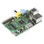
 I chose a Raspberry Pi model 2B for this project, mostly because I had a few of them lying around and they are relatively inexpensive. I also bought a small breakout board that connected to the Pi using a ribbon cable, giving me the ability to disconnect the pi from the rest of the project without having to unplug all the individual jumper wires.
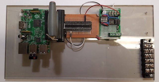
I mounted the Pi and breakout board on a piece of clear acrylic using some scavenged motherboard standoffs, leaving lots of room since at that point I wasn't really sure how big this project would grow. For the operating system I went with Raspbian Lite, because if you’re going to run Linux on a Pi, you might as well use the distribution that was built with the Pi in mind. With the basic hardware built, and the Pi up and running, it was time to start building.
The first thing I did was to replicate the functionality of my original project, which was to monitor the signal wire of my interconnected smoke detectors, and send me an email when they sounded an alarm. Most of these systems seem to send a 9V signal on the signal wire when sounding, but you should use a volt-meter to make sure your system uses the same signaling voltage if you intend on replicating this project. I also decided that it would be good form to electrically isolate the Pi from the smoke detectors, so I used an opto-isolator, which are handy little devices that couple an LED and light sensing diode to send an on or off signal between circuits without electrically connecting them. The opto-isolators I used were small, 4-pin dip form, and all I had lying around were 16-pin sockets. Since this seemed like something that might come in handy 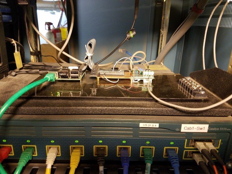 again, I went ahead and built the associated circuitry and input/output pins for four opto-isolators on a small piece of PCB board, and afixed it to the piece of acrylic that held the Pi. I then wired it to a 3.3V, Ground, and GPIO pin on the Pi, and ran wire from the other side of the circuit to the closest electrical junction box that contained the wires for my interconnected smoke detectors in order to tap into the signal wire and the ground. For me this was easy because I did the electrical wiring in my house, and I purposely put a junction box from that system next to my network cabinet.
If you are not so lucky, it may be more difficult to hardwire your project to your smoke detectors, and you may want to look at a wireless solution. The Raspberry Pi model 3B comes equipped with both Bluetooth and Wifi, so it wouldn't be that difficult to engineer an inexpensive wireless solution.
With the hardware in place, all I had to do was write a short Python script to monitor the GPIO pin on the Pi that was wired to the opto-isolator. I set it to look for both rising and falling edges, so that I could send one email if the smoke detectors started to alarm, and a second email when they stopped alarming. For the sake of brevity I won't post the script here, but you can see it on my blog, along with more detail and schematics for the hardware at http://madlab5.blogspot.com/2017/06/email-smoke-detector-using-raspberry-pi.html
After running the Pi for several weeks and testing it and the smoke detectors from time to time, I was satisfied that the system was stable and I could start expanding. At the time I was trying to grow some new grass in my backyard due to some previous construction, and I needed to run sprinklers to keep the ground moist. I was also building a new garden area for planting the following year, so I decided that giving my Pi the ability to control some sprinklers in the backyard would be a useful upgrade. I wanted to focus on the ability to repurpose this project since I knew I wouldn't need the sprinklers on the new grass next year, but I might need them up in the new garden, so my solution was to use the Pi to automate a hose bib on the outside of my house. I could then hook up any length of hose I chose and put any type of watering device anywhere I wanted.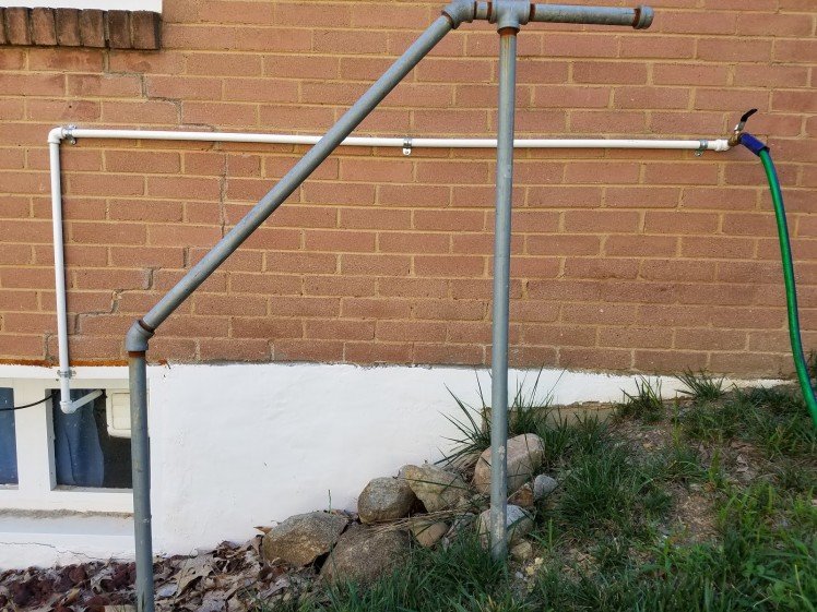
The hardware half of this project was solved using a 12V solenoid valve, a relay, and a 120VAC to 12VDC transformer. The relay was controlled by the Pi, and closed the circuit that allowed the 12V power supply to power the solenoid valve, subsequently opening the flow of water to the hose bib that I installed on the side of the house. The plumbing side of things took some time, and if you are trying to replicate this project, then please take the time to understand the physics of plumbing, and include all necessary check valves, cut-off valves, and drain for cold-weatherization. The last thing you want to do is to cause problems with the water pipes in your home. The relay I used was a JBtek model, which came in a typical 4-relay configuration, with each relay rated for 10 amps. The solenoid valve required 3 amps at 12V, so I threw a 3 amp fuse inline to protect both the relay and the solenoid. I also added a cut-off switch to cut 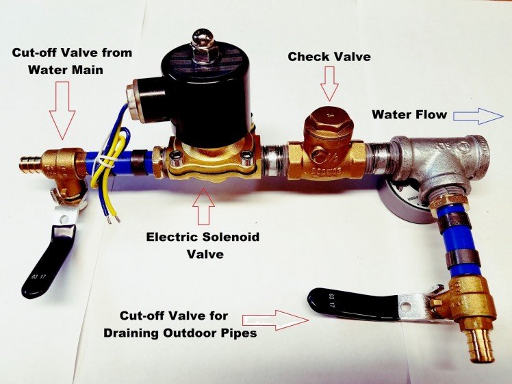 power to the system, as well as an override switch to turn on the sprinklers manually without having to log-onto the Pi. With all the hardware built and thoroughly tested I moved on to the software side of things.
The software for the sprinklers turned out to be relatively simple. I had to write a short start-up script to initialize the GPIO pin that controlled the sprinkler, and make sure the sprinkler was off at start-up. I then wrote two more short scripts named water-on and water-off, which as their name suggests, switched the GPIO pin between high and low in order to turn the water on and off. For scheduling I decided to use cron, Linux's built in scheduling system, so no code was necessary. I simply scheduled the water-on 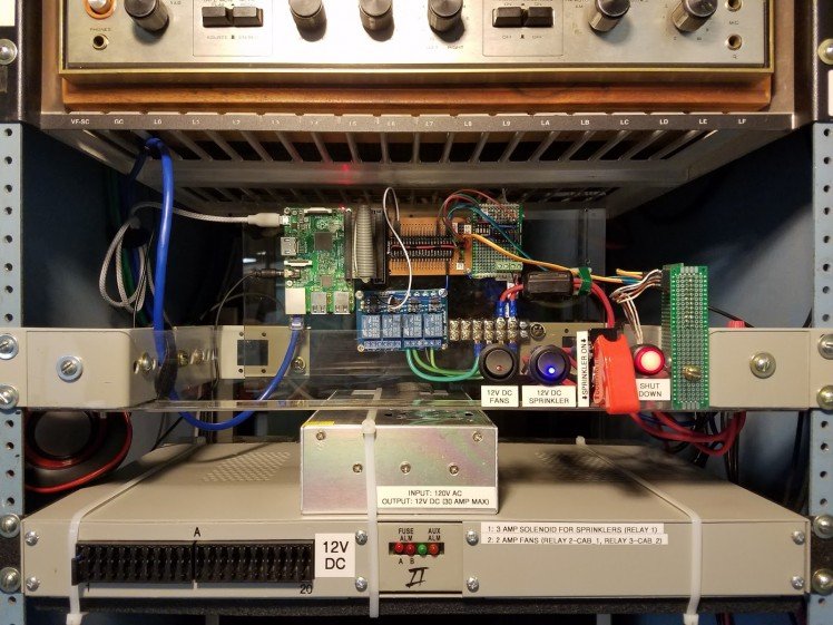 script to run every morning at 6 am, and then I scheduled the water-off script to run 20 minutes later. The schedule can be easily adjusted by editing the cron file. For more detail on this part of the project including specifics regarding the plumbing hardware, and the actual script, you can see my blog at http://madlab5.blogspot.com/2017/07/watering-garden-with-raspberry-pi.html
While I was building the sprinkler part of this project, the smoke detector monitor was online and the Pi was running headless in my network cabinet. I found myself needing to shutdown the Pi several times in order to install and adjust new hardware. Since the Pi does not come with a built-in shutdown button, I found myself having to remotely SSH into the Pi with another computer just to issue the shutdown command, since turning it off by simply pulling the power would risk data loss. This became enough of a frustration that I decided that it would be worth it to add a shutdown button to this project. Minimally, all I would need to do would be to allow a button an a small bit of circuitry to control a GPIO pin, and write a small script that would issue the shutdown command when the button was pressed, but I thought I could make this part of my project a little more interesting. First, it occured to me that I might want some sort of visual notification that the Pi was powered on, as well as a visual notification that the button had been pressed and the shutdown process had been started. A way to abort the shutdown process would also be helpful in the case that it was accidentally pressed. The final solution ended up involving a red button with a built-in LED that illuminated the button. I wrote a script to run on start-up that kept the button lit while the Pi was powered-on.
When the button was pressed it would flash for thirty seconds, and if the button was pressed again during that thirty seconds the shutdown process would stop, and the light would go back to a solid illumination. If the button was not pressed a second time after 30 seconds then the Pi would shutdown and the light would go off. The last little touch I added to the shutdown button was to give it a voice. The Raspberry Pi comes equipped with a 3.5mm audio jack, so I went on Amazon and found a small, cheap pair of speakers for under $5. Now when the button is pressed, instead of simply flashing, an audible voice explains that the Pi is preparing to shutdown, and if you would like to abort the shutdown you need to press the button again. If you would like to see this button in action, or the wiring diagram or Python script, you can visit my blog at http://madlab5.blogspot.com/2017/06/adding-soft-shutdown-switch-to-headless.htmlThe last thing I added to my home automation center in 2017 was the ability to monitor the temperature in my network cabinets, and the ability to control cooling fans based off of those temperature readings. This project was partially motivated by my desire to work with I2C protocol (also referred to as I2C or IIC), which is a two wire serial protocol with the convenient property of being able to stack several devices on the same two wire bus. It does this by designating one device as the master, and making a rule that only the master can initiate communication. In addition, each slave device is assigned a 7-bit address for identification. The reason I wanted to use I2C, other than as an excuse to try something new, was to try to conserve GPIO pins on my Pi. Instead of having to use different GPIO pins for every sensor, as well as several for the 7-segment display I wanted to use, I was 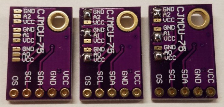 able to use two GPIO, one power, and one ground pin for the entire portion of this project. That leaves me plenty of pins left-over for future projects. I will add a link to my blog post on I2C at the end of this section if you want to read about I2C in more detail.
Last summer I found myself inspired when I stumbled across an old hacked up WRT54GL router that I had repurposed to monitor my interconnected smoke detectors and send me an email if they began to sound.
Back then, if one wanted a small Linux-based single board computer with UART and a few GPIOs (5 to be exact), one purchased the Linksys WRT54GL and re-flashed it with one of many open-source operating systems such as OpenWRT... good times. It occurred to me that the popular Raspberry Pi, with it's juicy 28 GPIOs, would be the perfect platform to revisit that old project and make some improvements.
Several months later that idea had grown into a small home automation center with plenty of room for expansion. After monitoring the smoke alarms, I expanded the Pi's functionality to include scheduling sprinklers in my yard and cooling off my network cabinets by monitoring the temperature and controlling fans. Modularity and expandability were my focus, and I expect this little guy to take on more responsibility in the future.
I chose a Raspberry Pi model 2B for this project, mostly because I had a few of them lying around and they are relatively inexpensive. I also bought a small breakout board that connected to the Pi using a ribbon cable, giving me the ability to disconnect the pi from the rest of the project without having to unplug all the individual jumper wires.
I mounted the Pi and breakout board on a piece of clear acrylic using some scavenged motherboard standoffs, leaving lots of room since at that point I wasn't really sure how big this project would grow. For the operating system I went with Raspbian Lite, because if you’re going to run Linux on a Pi, you might as well use the distribution that was built with the Pi in mind. With the basic hardware built, and the Pi up and running, it was time to start building.
The first thing I did was to replicate the functionality of my original project, which was to monitor the signal wire of my interconnected smoke detectors, and send me an email when they sounded an alarm. Most of these systems seem to send a 9V signal on the signal wire when sounding, but you should use a volt-meter to make sure your system uses the same signaling voltage if you intend on replicating this project. I also decided that it would be good form to electrically isolate the Pi from the smoke detectors, so I used an opto-isolator, which are handy little devices that couple an LED and light sensing diode to send an on or off signal between circuits without electrically connecting them. The opto-isolators I used were small, 4-pin dip form, and all I had lying around were 16-pin sockets. Since this seemed like something that might come in handy again, I went ahead and built the associated circuitry and input/output pins for four opto-isolators on a small piece of PCB board, and afixed it to the piece of acrylic that held the Pi. I then wired it to a 3.3V, Ground, and GPIO pin on the Pi, and ran wire from the other side of the circuit to the closest electrical junction box that contained the wires for my interconnected smoke detectors in order to tap into the signal wire and the ground. For me this was easy because I did the electrical wiring in my house, and I purposely put a junction box from that system next to my network cabinet.
If you are not so lucky, it may be more difficult to hardwire your project to your smoke detectors, and you may want to look at a wireless solution. The Raspberry Pi model 3B comes equipped with both Bluetooth and Wifi, so it wouldn't be that difficult to engineer an inexpensive wireless solution.
With the hardware in place, all I had to do was write a short Python script to monitor the GPIO pin on the Pi that was wired to the opto-isolator. I set it to look for both rising and falling edges, so that I could send one email if the smoke detectors started to alarm, and a second email when they stopped alarming. For the sake of brevity I won't post the script here, but you can see it on my blog, along with more detail and schematics for the hardware at http://madlab5.blogspot.com/2017/06/email-smoke-detector-using-raspberry-pi.html
After running the Pi for several weeks and testing it and the smoke detectors from time to time, I was satisfied that the system was stable and I could start expanding. At the time I was trying to grow some new grass in my backyard due to some previous construction, and I needed to run sprinklers to keep the ground moist. I was also building a new garden area for planting the following year, so I decided that giving my Pi the ability to control some sprinklers in the backyard would be a useful upgrade. I wanted to focus on the ability to repurpose this project since I knew I wouldn't need the sprinklers on the new grass next year, but I might need them up in the new garden, so my solution was to use the Pi to automate a hose bib on the outside of my house. I could then hook up any length of hose I chose and put any type of watering device anywhere I wanted.
The hardware half of this project was solved using a 12V solenoid valve, a relay, and a 120VAC to 12VDC transformer. The relay was controlled by the Pi, and closed the circuit that allowed the 12V power supply to power the solenoid valve, subsequently opening the flow of water to the hose bib that I installed on the side of the house. The plumbing side of things took some time, and if you are trying to replicate this project, then please take the time to understand the physics of plumbing, and include all necessary check valves, cut-off valves, and drain for cold-weatherization. The last thing you want to do is to cause problems with the water pipes in your home. The relay I used was a JBtek model, which came in a typical 4-relay configuration, with each relay rated for 10 amps. The solenoid valve required 3 amps at 12V, so I threw a 3 amp fuse inline to protect both the relay and the solenoid. I also added a cut-off switch to cut power to the system, as well as an override switch to turn on the sprinklers manually without having to log-onto the Pi. With all the hardware built and thoroughly tested I moved on to the software side of things.
The software for the sprinklers turned out to be relatively simple. I had to write a short start-up script to initialize the GPIO pin that controlled the sprinkler, and make sure the sprinkler was off at start-up. I then wrote two more short scripts named water-on and water-off, which as their name suggests, switched the GPIO pin between high and low in order to turn the water on and off. For scheduling I decided to use cron, Linux's built in scheduling system, so no code was necessary. I simply scheduled the water-on script to run every morning at 6 am, and then I scheduled the water-off script to run 20 minutes later. The schedule can be easily adjusted by editing the cron file. For more detail on this part of the project including specifics regarding the plumbing hardware, and the actual script, you can see my blog at http://madlab5.blogspot.com/2017/07/watering-garden-with-raspberry-pi.html
While I was building the sprinkler part of this project, the smoke detector monitor was online and the Pi was running headless in my network cabinet. I found myself needing to shutdown the Pi several times in order to install and adjust new hardware. Since the Pi does not come with a built-in shutdown button, I found myself having to remotely SSH into the Pi with another computer just to issue the shutdown command, since turning it off by simply pulling the power would risk data loss. This became enough of a frustration that I decided that it would be worth it to add a shutdown button to this project. Minimally, all I would need to do would be to allow a button an a small bit of circuitry to control a GPIO pin, and write a small script that would issue the shutdown command when the button was pressed, but I thought I could make this part of my project a little more interesting. First, it occured to me that I might want some sort of visual notification that the Pi was powered on, as well as a visual notification that the button had been pressed and the shutdown process had been started. A way to abort the shutdown process would also be helpful in the case that it was accidentally pressed. The final solution ended up involving a red button with a built-in LED that illuminated the button. I wrote a script to run on start-up that kept the button lit while the Pi was powered-on.
When the button was pressed it would flash for thirty seconds, and if the button was pressed again during that thirty seconds the shutdown process would stop, and the light would go back to a solid illumination. If the button was not pressed a second time after 30 seconds then the Pi would shutdown and the light would go off. The last little touch I added to the shutdown button was to give it a voice. The Raspberry Pi comes equipped with a 3.5mm audio jack, so I went on Amazon and found a small, cheap pair of speakers for under $5. Now when the button is pressed, instead of simply flashing, an audible voice explains that the Pi is preparing to shutdown, and if you would like to abort the shutdown you need to press the button again. If you would like to see this button in action, or the wiring diagram or Python script, you can visit my blog at http://madlab5.blogspot.com/2017/06/adding-soft-shutdown-switch-to-headless.htmlThe last thing I added to my home automation center in 2017 was the ability to monitor the temperature in my network cabinets, and the ability to control cooling fans based off of those temperature readings. This project was partially motivated by my desire to work with I2C protocol (also referred to as I2C or IIC), which is a two wire serial protocol with the convenient property of being able to stack several devices on the same two wire bus. It does this by designating one device as the master, and making a rule that only the master can initiate communication. In addition, each slave device is assigned a 7-bit address for identification. The reason I wanted to use I2C, other than as an excuse to try something new, was to try to conserve GPIO pins on my Pi. Instead of having to use different GPIO pins for every sensor, as well as several for the 7-segment display I wanted to use, I was able to use two GPIO, one power, and one ground pin for the entire portion of this project. That leaves me plenty of pins left-over for future projects. I will add a link to my blog post on I2C at the end of this section if you want to read about I2C in more detail.
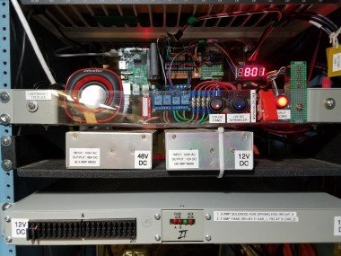
The hardware I chose for detecting the temperature was a CJMCU-75, which uses an LM57A temperature sensor. These inexpensive little devices have onboard analog to digital conversion, as well as the ability to set the I2C address on each individual sensor. I also purchased a product made by Adafruit called the I2C backpack, which allows a typical 4-digit 7-segment display to be programmed using I2C protocol. Like the sensors, the Backpack also allows for a programmable address, so I was able to use it on the same 2-wire bus I used for the sensors. The last part of the hardware to work out were the cooling fans. Since most computer fans run on 12V, and I had plenty of left-over amperage from the power supply I used for the sprinkler project, I just bought some 12V computer fans.
 I was also able to use two of the relays leftover from the sprinkler project to switch the fans on/off since I had purchased a 4-relay board and only used one of the relays. Of course I added an inline fuse to protect the fans and relays.
Once all of the hardware was wired up and tested, it was time to get to programming. I wrote a Python script that ran in a loop. Each cycle it would take a temperature reading from each sensor, one for each network cabinet and a third for the ambient temperature in the room. It would then print out temperatures one by one on the 7-segment display, pausing briefly on each one. I used hex digits on the 7-segment display to be able to reference the sensors as cab1, cab2, and ba5e (for basement). Before restarting the cycle it also displays the time, just for good measure. It also compared the temperatures in the cabinets to a predefined threshold and turned the fans on if necessary. If the fans were already on it compared the temperature to a lower threshold to see if they could be turned back off. 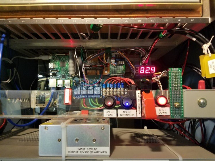 The final task in each iteration of the loop was to check the temperatures against a third, higher threshold, and send me an email if the temperature had become dangerously high in the network cabinets, indicating that the fans had failed or that they could not keep up with the heat being generated. As with the other sections, if you would like to read more about the protocols used, see the schematics for the hardware, or view the Python script I wrote, you can do so on my blog post for this section of the project at http://madlab5.blogspot.com/2017/08/reading-temperature-sensors-and.html
I hope you have enjoyed the write-up on my home automation center. I’m looking forward to giving it even more responsibility in 2018. If you have any ideas for additional tasks I could delegate to this Raspberry Pi I’d love to hear from you. Until next time, stay safe and keep building.
Once all of the hardware was wired up and tested, it was time to get to programming. I wrote a Python script that ran in a loop. Each cycle it would take a temperature reading from each sensor, one for each network cabinet and a third for the ambient temperature in the room. It would then print out temperatures one by one on the 7-segment display, pausing briefly on each one. I used hex digits on the 7-segment display to be able to reference the sensors as cab1, cab2, and ba5e (for basement). Before restarting the cycle it also displays the time, just for good measure. It also compared the temperatures in the cabinets to a predefined threshold and turned the fans on if necessary. If the fans were already on it compared the temperature to a lower threshold to see if they could be turned back off. The final task in each iteration of the loop was to check the temperatures against a third, higher threshold, and send me an email if the temperature had become dangerously high in the network cabinets, indicating that the fans had failed or that they could not keep up with the heat being generated. As with the other sections, if you would like to read more about the protocols used, see the schematics for the hardware, or view the Python script I wrote, you can do so on my blog post for this section of the project at http://madlab5.blogspot.com/2017/08/reading-temperature-sensors-and.html
I hope you have enjoyed the write-up on my home automation center. I’m looking forward to giving it even more responsibility in 2018. If you have any ideas for additional tasks I could delegate to this Raspberry Pi I’d love to hear from you. Until next time, stay safe and keep building.
The Word to HTML converter helps you convert documents like Excel, Google docs, PDF files and any other visual document to HTML.
Back then, if one wanted a small Linux-based single board computer with UART and a few GPIOs (5 to be exact), one purchased the Linksys WRT54GL and re-flashed it with one of many open-source operating systems such as OpenWRT... good times. It occurred to me that the popular Raspberry Pi, with it's juicy 28 GPIOs, would be the perfect platform to revisit that old project and make some improvements.
Several months later that idea had grown into a small home automation center with plenty of room for expansion. After monitoring the smoke alarms, I expanded the Pi's functionality to include scheduling sprinklers in my yard and cooling off my network cabinets by monitoring the temperature and controlling fans. Modularity and expandability were my focus, and I expect this little guy to take on more responsibility in the future.
I chose a Raspberry Pi model 2B for this project, mostly because I had a few of them lying around and they are relatively inexpensive. I also bought a small breakout board that connected to the Pi using a ribbon cable, giving me the ability to disconnect the pi from the rest of the project without having to unplug all the individual jumper wires.
I mounted the Pi and breakout board on a piece of clear acrylic using some scavenged motherboard standoffs, leaving lots of room since at that point I wasn't really sure how big this project would grow. For the operating system I went with Raspbian Lite, because if you’re going to run Linux on a Pi, you might as well use the distribution that was built with the Pi in mind. With the basic hardware built, and the Pi up and running, it was time to start building.
The first thing I did was to replicate the functionality of my original project, which was to monitor the signal wire of my interconnected smoke detectors, and send me an email when they sounded an alarm. Most of these systems seem to send a 9V signal on the signal wire when sounding, but you should use a volt-meter to make sure your system uses the same signaling voltage if you intend on replicating this project. I also decided that it would be good form to electrically isolate the Pi from the smoke detectors, so I used an opto-isolator, which are handy little devices that couple an LED and light sensing diode to send an on or off signal between circuits without electrically connecting them. The opto-isolators I used were small, 4-pin dip form, and all I had lying around were 16-pin sockets. Since this seemed like something that might come in handy again, I went ahead and built the associated circuitry and input/output pins for four opto-isolators on a small piece of PCB board, and afixed it to the piece of acrylic that held the Pi. I then wired it to a 3.3V, Ground, and GPIO pin on the Pi, and ran wire from the other side of the circuit to the closest electrical junction box that contained the wires for my interconnected smoke detectors in order to tap into the signal wire and the ground. For me this was easy because I did the electrical wiring in my house, and I purposely put a junction box from that system next to my network cabinet.
If you are not so lucky, it may be more difficult to hardwire your project to your smoke detectors, and you may want to look at a wireless solution. The Raspberry Pi model 3B comes equipped with both Bluetooth and Wifi, so it wouldn't be that difficult to engineer an inexpensive wireless solution.
With the hardware in place, all I had to do was write a short Python script to monitor the GPIO pin on the Pi that was wired to the opto-isolator. I set it to look for both rising and falling edges, so that I could send one email if the smoke detectors started to alarm, and a second email when they stopped alarming. For the sake of brevity I won't post the script here, but you can see it on my blog, along with more detail and schematics for the hardware at http://madlab5.blogspot.com/2017/06/email-smoke-detector-using-raspberry-pi.html
After running the Pi for several weeks and testing it and the smoke detectors from time to time, I was satisfied that the system was stable and I could start expanding. At the time I was trying to grow some new grass in my backyard due to some previous construction, and I needed to run sprinklers to keep the ground moist. I was also building a new garden area for planting the following year, so I decided that giving my Pi the ability to control some sprinklers in the backyard would be a useful upgrade. I wanted to focus on the ability to repurpose this project since I knew I wouldn't need the sprinklers on the new grass next year, but I might need them up in the new garden, so my solution was to use the Pi to automate a hose bib on the outside of my house. I could then hook up any length of hose I chose and put any type of watering device anywhere I wanted.
The hardware half of this project was solved using a 12V solenoid valve, a relay, and a 120VAC to 12VDC transformer. The relay was controlled by the Pi, and closed the circuit that allowed the 12V power supply to power the solenoid valve, subsequently opening the flow of water to the hose bib that I installed on the side of the house. The plumbing side of things took some time, and if you are trying to replicate this project, then please take the time to understand the physics of plumbing, and include all necessary check valves, cut-off valves, and drain for cold-weatherization. The last thing you want to do is to cause problems with the water pipes in your home. The relay I used was a JBtek model, which came in a typical 4-relay configuration, with each relay rated for 10 amps. The solenoid valve required 3 amps at 12V, so I threw a 3 amp fuse inline to protect both the relay and the solenoid. I also added a cut-off switch to cut power to the system, as well as an override switch to turn on the sprinklers manually without having to log-onto the Pi. With all the hardware built and thoroughly tested I moved on to the software side of things.
The software for the sprinklers turned out to be relatively simple. I had to write a short start-up script to initialize the GPIO pin that controlled the sprinkler, and make sure the sprinkler was off at start-up. I then wrote two more short scripts named water-on and water-off, which as their name suggests, switched the GPIO pin between high and low in order to turn the water on and off. For scheduling I decided to use cron, Linux's built in scheduling system, so no code was necessary. I simply scheduled the water-on script to run every morning at 6 am, and then I scheduled the water-off script to run 20 minutes later. The schedule can be easily adjusted by editing the cron file. For more detail on this part of the project including specifics regarding the plumbing hardware, and the actual script, you can see my blog at http://madlab5.blogspot.com/2017/07/watering-garden-with-raspberry-pi.html
While I was building the sprinkler part of this project, the smoke detector monitor was online and the Pi was running headless in my network cabinet. I found myself needing to shutdown the Pi several times in order to install and adjust new hardware. Since the Pi does not come with a built-in shutdown button, I found myself having to remotely SSH into the Pi with another computer just to issue the shutdown command, since turning it off by simply pulling the power would risk data loss. This became enough of a frustration that I decided that it would be worth it to add a shutdown button to this project. Minimally, all I would need to do would be to allow a button an a small bit of circuitry to control a GPIO pin, and write a small script that would issue the shutdown command when the button was pressed, but I thought I could make this part of my project a little more interesting. First, it occured to me that I might want some sort of visual notification that the Pi was powered on, as well as a visual notification that the button had been pressed and the shutdown process had been started. A way to abort the shutdown process would also be helpful in the case that it was accidentally pressed. The final solution ended up involving a red button with a built-in LED that illuminated the button. I wrote a script to run on start-up that kept the button lit while the Pi was powered-on.
When the button was pressed it would flash for thirty seconds, and if the button was pressed again during that thirty seconds the shutdown process would stop, and the light would go back to a solid illumination. If the button was not pressed a second time after 30 seconds then the Pi would shutdown and the light would go off. The last little touch I added to the shutdown button was to give it a voice. The Raspberry Pi comes equipped with a 3.5mm audio jack, so I went on Amazon and found a small, cheap pair of speakers for under $5. Now when the button is pressed, instead of simply flashing, an audible voice explains that the Pi is preparing to shutdown, and if you would like to abort the shutdown you need to press the button again. If you would like to see this button in action, or the wiring diagram or Python script, you can visit my blog at http://madlab5.blogspot.com/2017/06/adding-soft-shutdown-switch-to-headless.htmlThe last thing I added to my home automation center in 2017 was the ability to monitor the temperature in my network cabinets, and the ability to control cooling fans based off of those temperature readings. This project was partially motivated by my desire to work with I2C protocol (also referred to as I2C or IIC), which is a two wire serial protocol with the convenient property of being able to stack several devices on the same two wire bus. It does this by designating one device as the master, and making a rule that only the master can initiate communication. In addition, each slave device is assigned a 7-bit address for identification. The reason I wanted to use I2C, other than as an excuse to try something new, was to try to conserve GPIO pins on my Pi. Instead of having to use different GPIO pins for every sensor, as well as several for the 7-segment display I wanted to use, I was able to use two GPIO, one power, and one ground pin for the entire portion of this project. That leaves me plenty of pins left-over for future projects. I will add a link to my blog post on I2C at the end of this section if you want to read about I2C in more detail.
The hardware I chose for detecting the temperature was a CJMCU-75, which uses an LM57A temperature sensor. These inexpensive little devices have onboard analog to digital conversion, as well as the ability to set the I2C address on each individual sensor. I also purchased a product made by Adafruit called the I2C backpack, which allows a typical 4-digit 7-segment display to be programmed using I2C protocol. Like the sensors, the Backpack also allows for a programmable address, so I was able to use it on the same 2-wire bus I used for the sensors. The last part of the hardware to work out were the cooling fans. Since most computer fans run on 12V, and I had plenty of left-over amperage from the power supply I used for the sprinkler project, I just bought some 12V computer fans. I was also able to use two of the relays leftover from the sprinkler project to switch the fans on/off since I had purchased a 4-relay board and only used one of the relays. Of course I added an inline fuse to protect the fans and relays.
Once all of the hardware was wired up and tested, it was time to get to programming. I wrote a Python script that ran in a loop. Each cycle it would take a temperature reading from each sensor, one for each network cabinet and a third for the ambient temperature in the room. It would then print out temperatures one by one on the 7-segment display, pausing briefly on each one. I used hex digits on the 7-segment display to be able to reference the sensors as cab1, cab2, and ba5e (for basement). Before restarting the cycle it also displays the time, just for good measure. It also compared the temperatures in the cabinets to a predefined threshold and turned the fans on if necessary. If the fans were already on it compared the temperature to a lower threshold to see if they could be turned back off. The final task in each iteration of the loop was to check the temperatures against a third, higher threshold, and send me an email if the temperature had become dangerously high in the network cabinets, indicating that the fans had failed or that they could not keep up with the heat being generated. As with the other sections, if you would like to read more about the protocols used, see the schematics for the hardware, or view the Python script I wrote, you can do so on my blog post for this section of the project at http://madlab5.blogspot.com/2017/08/reading-temperature-sensors-and.html
I hope you have enjoyed the write-up on my home automation center. I’m looking forward to giving it even more responsibility in 2018. If you have any ideas for additional tasks I could delegate to this Raspberry Pi I’d love to hear from you. Until next time, stay safe and keep building.
The Word to HTML converter helps you convert documents like Excel, Google docs, PDF files and any other visual document to HTML.
Credits
Related products


Leave your feedback...