
Raspberry Alarm Upgrade

Made by Muls96 / Clocks / Communication / Games & Gaming / Notifications / Sensors
About the project
In this Project, my 20 years old alarm system gets an upgrade, email and SMS warnings replace the old phone calling notification.
Project info
Difficulty: Easy
Platforms: Raspberry Pi
Estimated time: 1 hour
License: GNU General Public License, version 3 or later (GPL3+)
Items used in this project
Hardware components

Story

Details
Project definition
Even though the alarm system is pretty old, its design is hacker friendly. The motherboard has a 12V power output that can be used for future extension cards. This is the power output I used. When something is detected, the siren is triggered by an output and the voltage drops from 12V to 0V.This is very convenient for my project !
The system must be able to notify me in any conditions, for that reason I wanted three warning types:
-Email : Even if I don't have my phone I can get notifications on my laptop
-SMS : The most convenient way to notify someone
-Call : At night my laptop and my smartphone are turned off, the only communication available is my fixed-line phone
Interfaces and Components
The first type of notification is easily doable with Python on the Raspberry pi. The two others will be handled by a GSM modem.
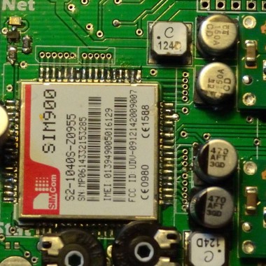
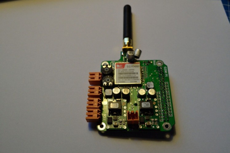
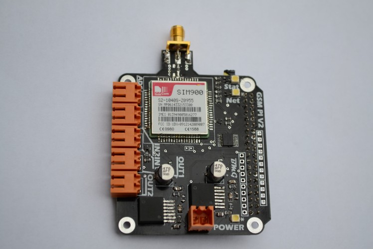
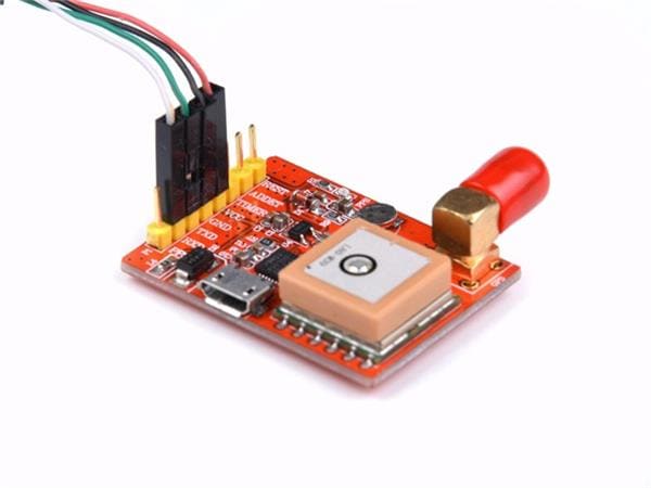
For the modem I used a SIM900 : a popular component with a great online community support.
I needed two power supplies, 5V for the Raspberry pi and 4V for the GSM module. I used two TI PTN78000W series because they have a high efficiency and great output current.
The last and more important interface is the siren trigger. I used optocouplers to step down the voltage to 3.3v and protect the Raspberry pi.
Project Logs
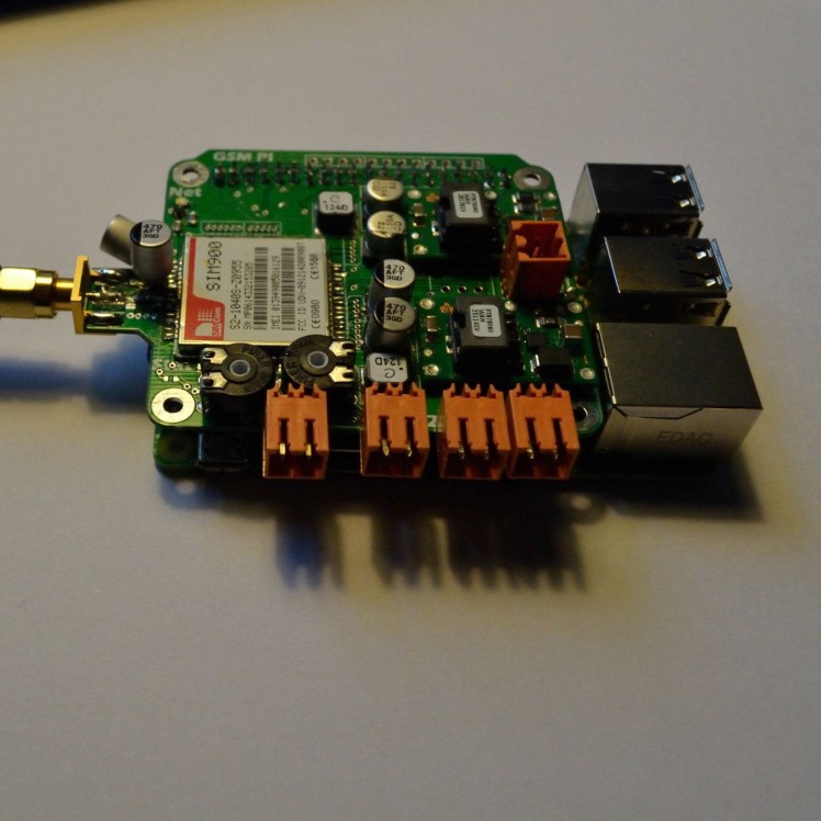
New board soldered and code available
I got some time to solder the board and push some code. I haven't fully tested the board yet. It appears that you cannot power the raspberry pi 2 from the GPIO header, thus the board might not be 100% compatible with it.
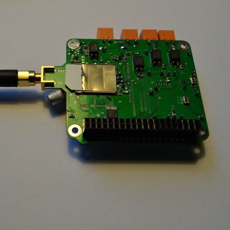
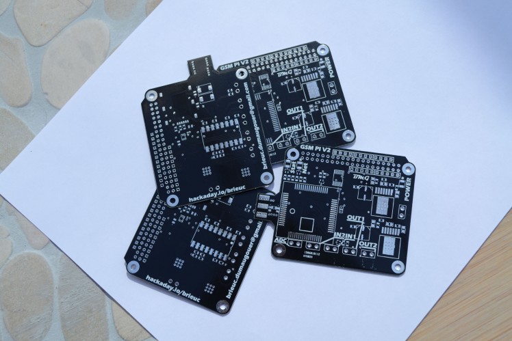
New PCBs just arrived
I received this morning the new version of the PCB from China. If this version doesn't have errors, I will release all the design files.
New version coming soon !
Just graduated !! Aside from looking for a job, I'll have some time to update this project and release hardware design files as well as software !! Stay tuned !
Brieuc :
24/01/2015
Done :
The warning system is implemented and working
To do :
Correct software bugs
Troubleshoot the battery voltage monitoring
Upload code examples
Upload PCB schematics and layout
New PCB
- add capacitors next to the Module
-change the SIM card slot location (the sma connector is blocking the slot)
-new battery watching interface
-improve component placement
Credits
Related products


Leave your feedback...