

Psoc 6 Audio Sensor

Made by bastiaanslee / Communication / Sensors
About the project
Truly listen to what is around you, with the use of some electronics of course. Microphones can 'hear' more than your ears. This project will guide you through measurement, calculations and interpretation of that!
Project info
Difficulty: Difficult
Estimated time: 2 weeks
License: GNU General Public License, version 3 or later (GPL3+)
Items used in this project
Hardware components
Software apps and online services
Story
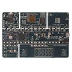
For the "The Great PSoC 6 Design Challenge", Electromaker did provide me a Cypress PSoC 6 - WiFi BT Prototyping Kit (CY8CPROTO-062-4343W). A development board that is roughly 12 by 8 centimeter in size. The MCU on this board is of course the PSoC 6 chipset with dual cores: one 150-MHz Arm Cortex-M4 and one 100-MHz Arm Cortex-M0+.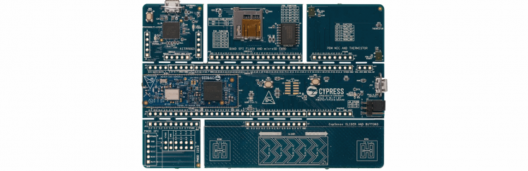
One of the nice features here, is that once your prototyping is complete, the board can be broken into 6 pieces, and you only keep the parts that you need for your project. The main board is 12 by 2.7 centimeter and has all you need for basics: the MCU, WiFi, Bluetooth, a button and an LED. A plethora of pins are broken out around it.
Then you have 5 parts that you can mix-'n-match for your project needs:
- An SD Card Reader & Flash Memory
- Two PDM Microphones and a Thermistor
- A CapSense Slider and Buttons
- A Digilent PMOD Interface to easily connect external boards (once headers are soldered on)
- The KitProg3 on-board Programmer & Debugger (of course once your project is complete, you don't need this part anymore)
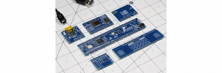 Image source: Jeremy S. Cook
What will I make with that?
There is always one big question when you subscribe to a contest; "What will you make?"
My plan was to use this board with the stereo microphone, to capture sounds and process that to find out if there are sonar calls from bats. Results are to be uploaded to an Influx database, possibly via NodeRED for data manipulation. And graphing can be done in Grafana. If time permitted, I wanted to extend this to find out if I can distinguish different types of bats.
Well, that went a bit differently... I did see the last bats flying in November, but when I got the board in December, bats where all in their winter hibernation. And a technical issue; the microphones would not be able to process sonar sounds (more on that later). So that would be a nice programming experience, with no testing evidence...
No worries, I started working with the board anyway to get the microphones working. First the example sketches for the CapSense and Audio/Volume, then combined the two. Next added WiFi connection to it, and then sent the volume to InfluxDB. It took some time to get used to the Eclipse IDE for ModusToolbox, but after some weeks of playing, it worked quite steady.
But I wasn't satisfied yet, I wanted to do a more with the Sound/Audio part, more realtime, and more detail. And that was a wasp nest! To help you achieve the same, and don't get stung by the wasps, this project is to share my learned knowledge with you all!
You can watch this video that goes through all of this, or read the full project. The video will show you a live demo, including me playing saxophone (first time again since 25 years...)
Sound or Audio?
Sound is a vibration of air (or other medium), that by our ears and brains can be perceived as tones. It can be caused by any source.
Audio is referring to sound coming from a recording, transmission or electronic device.
As sound is recorded by the microphone and then turns into audio, when I talk about what happens in code, I call it audio. When it is about how your ears perceive something, I call it sound.
What is Sound?
Besides the short description above, lets explain that a bit deeper. Starting with how we perceive it with our ears and brains. Starting simple: somebody plays a flute in a steady tone, not too loud. This starts a vibration of the air. For now, think of that as a single wave pattern, we call that a frequency. If you draw this, this is a wave that goes up and down in a uniform looking form; a sine wave. The higher the tone, the higher the frequency is; shorter waves. The loudness defines how high or low the wave is. When somebody else plays a trumpet at a steady tone and somewhat louder, you will hear the tone height is different. That means it is in another frequency, presumably a lower frequency, and the energy is higher. And add a piano as well, also with a single steady tone, but very loud. We now have 3 different tones, 3 frequencies and a different loudness.
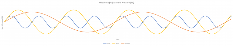
But frequencies is something we perceive with our ears, or if only one instrument at a time plays. At this point, we just talked about vibration of the air of single instrument. With our 3 instruments at a different frequencies and loudness, the overall air pressure will be a sum of the 3. So it looks more like this:
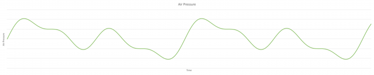
And that is the start of everything that is used for Sound and Audio processing!
Your ears: sound processing
Looking at the anatomy of your ears, air pressure causes the eardrum or membrane to vibrate. Which sets the three tiny bones in the middle ear into motion. The motion of the bones causes the fluid in the cochlea to move. The cochlea works as a frequency filter and sends detailed signals to your brains. The cochlea can register sounds from 20 Hz to 20 kHz. The NIH made a nice animation of this.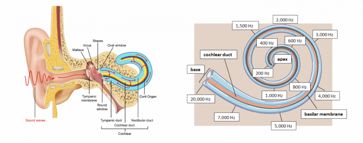
The voiced speech of a typical adult male will have a fundamental frequency from 85 to 180 Hz, and that of a typical adult female from 165 to 255 Hz [Source]. So that is what we at least need to capture crisp and clear.
At the edges the registration is less (compared to technical sound measurement), but in the middle around 2.5 kHz there is actually an amplifying peak. When you grow older, these edges do register less and less sound, mainly at the high frequency side. So you don't hear the high tones as good as a youngster anymore.
But it doesn’t tell you if you hear a piano, flute or trumpet! That is what your brains will do, based on lot's of other factors.
Microphones: audio processing
Our PSoC 6 Prototyping Kit has two Knowles SPK0838HT4H-B microphones, with a Frequency Response of 20 Hz - 20 kHz. As we did see from the cochlea, this is ideal for voice input! But we are missing out everything in higher frequencies, like the sonar sounds of the bats who use calls between 25 kHz and 120 kHz...
Most of the microphones used today, for example in your mobile phone or voice assistant, are MEMS (Micro-Electro-Mechanical System) microphones.
How do these work?
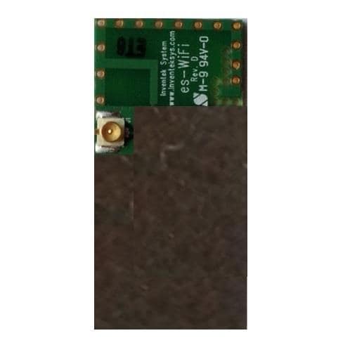
These microphones are little boxes on your PCB, sometimes looking like a little tin. The one on the PSoC board is a grey box (see the right-hand image below). At the top you can see a little hole. But there are also versions where the hole is at the bottom side, through the PCB.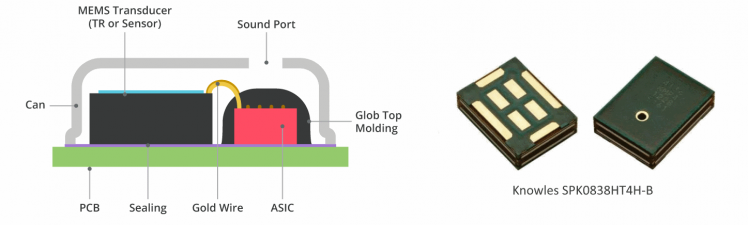 MEMS diaphragm registers the air pressure differences as an analog signal. It sends these analog signals to the ASIC (Application-Specific Integrated Circuit). The ASIC then translates this to a digital signal in PDM format.
PDM (Pulse-Density Modulation)
Pulse-Density Modulation is used to represent an analog signal with a binary signal. That means it does send LOW and HIGH pulses, in a frequency that was agreed upfront. The relative density of the pulses, corresponds to the analog signal amplitude. This is a modulation used for transmitting audio signals in a digital way. If you would make a picture of the signal, it looks kind of like a bar-code.
PCM (Pulse-Code Modulation)
To make it easier for our program to work with the signals, PDM is translated to Pulse-Code Modulation. This is still digital, but instead of LOW and HIGH, this presented with numbers. That makes it easier to let it look like our air pressure way of presentation. Depending on the number of readings, the line might be as fluid as here, or look more blocky.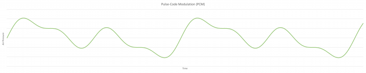
Audio Processing raw data
Of course you can write a program to listen to the PDM signals that are received, and translate that into PCM data. Luckily there is a standard for that, and Cypress did even give as a tool for it in ModusToolbox: the PDM-PCM conversion!
The output we get is in 16 bit word length, which we can convert to floats. The result we get now, is data between -1 and 1, with the center at 0.
As a recap; this is what our ears would hear with some help from our brains: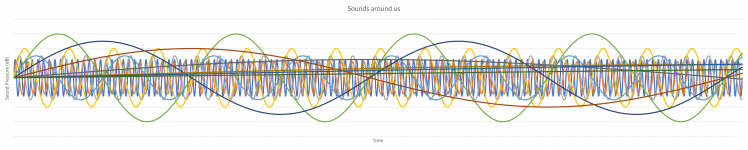
But this is what the microphone 'hears':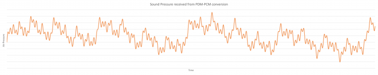
And that is exactly what we need for next steps!
Fourier Transform
In the world of mathematics, there is always somebody who finds a formula that fixes your problem. In this case, around 1822, a French mathematician Joseph Fourier, found a way transform time based data, into frequency based data, by splitting it into many repeatable functions. Although only long after that, this was valued to it's worth and got the name Fourier Transform. This mathematical solution is seen as one of the most important algorithms that exist. It is used for so many things around us. Just thinking of today's technology: voice calls, music, streaming video, image storing, file compression, etc.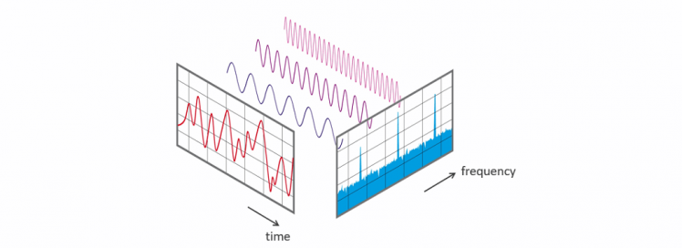
Sources I used to understand this, are this YouTube video from 3Blue1Brown that explains this very well, it made so many things clear for me! Then we have this page from Elan Ness-Cohn, with clear animated images, based on the information from 3Blue1Brown. And when you want to take a really deep dive into Fourier Transforms, watch this YouTube video series from Steve L. Brunton.
Hann Window
One of the inputs for the Fourier Transform, is the repeatable function. These are called Window functions. For audio transform, the Hann Window (also "Von Hann Window" or "Hanning Window") is most widely used. Remember our PDM-PCM input after the IntegerToFloat conversion was all between -1 and 1? In very simple words, the Hann Window makes sure all negative values are raised above 0, in fact to data between 0 and 1, with the center at 0.5.
Quick and very dirty Fourier Transform
If you wrap our data input as a circle around a mid-point, and calculate the Center of Mass of it, you will see it ends up somewhere close to the middle in most cases. If you then start to change the winding speed (the frequency) of that wrapped data, you will see that there are peaks occurring. This is the energy of that exact frequency. By going over half of the dataset, this will give a view of all our frequencies, and the energy for each of them.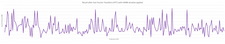
Octaves
To make something meaningful of that, we can bin the data into Octaves. In music, an octave is the interval between one musical pitch and another with double its frequency.
But for sound and audio processing, there are used Octave-bands. In our audible range of 20 Hz to 20 kHz, there are 10 Octave-bands, that have overlapping outer ranges.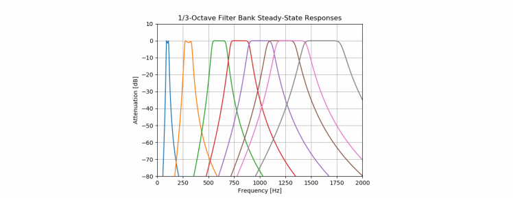
In the current code, all input is taken 100% from one octave to the next. So this could be improved!
What we effectively do, is that our Fourier Transform result, is split into equal pieces. Notice that above Octave-band visualization uses logarithmic horizontal ax, and in below visualization there is a normal horizontal ax. That is why the size of the octaves looks like it is getting larger.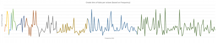
Then we sum the results of each piece together, divide it by the number of inputs, and we can see the total Sound Pressure per octave: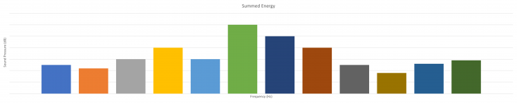
Frequency Weighting
Microphones are designed to hear everything within technical range
Your ears are designed to hear everything that is important
And with important, we mean "everything we need to survive". And you can see that in how our cochlea works: it can register sounds from 20 Hz to 20 kHz, with lower registration at the edges and amplification in the middle.
As our microphone did register everything that it could hear at a technical level, and that is different compared to what our ears would do before sending it off to your brains. The high and low tones have a much lower energy registration by our ears. So we have to correct our received audio for that.
This is what we call frequency weighting, where we mainly use 3 weightings:
- A-Weighting is used for quiet environments
- C-Weighting is used for noisy environments
- Z-Weighting is the “zero” line that is our microphone source
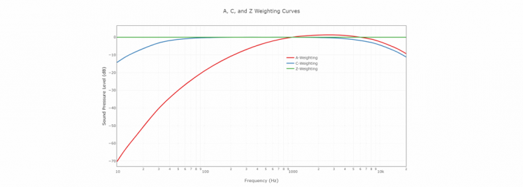
A full table of applied Weightings, can be found on the website from NTI-audio.
By limiting our readings following the A-Weighting, we get back to what our ears would have perceived: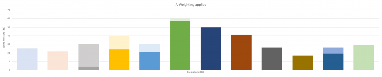
Instead of a table with a single value per (third of an) octave, we could also calculate with a formula what the detailed weighting would be in each reading of our dataset. But we would have to do that before we do split into the octave-bands. So the order of steps will be changed by that.
Now you know all you need for Sound and Audio processing to get to the next steps. Let's start digging into our software!
Single thread vs. Real Time Operating System
In classic "single thread" operating systems, all tasks will be executed one-by-one, in a predefined order.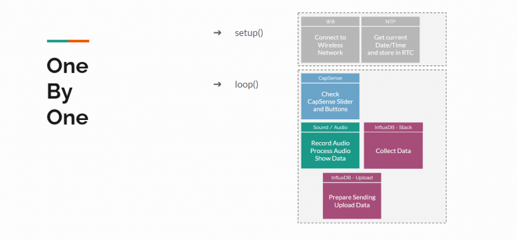
There usually is a "setup()" class that is used to initiate objects and configuration that is needed for all following code and only need to happen once. Then you use the "main()" or "loop()" class for the actual program. As the name says, the code loops through this endlessly. And everything happens after each other, there never is something that happens at the same time as something else. If we write our program very clever, the loop will be super fast and each step is touched within milliseconds. It could even serve steps into other processes/classes. But still, it has to wait for the process/class to complete before it goes to the next step.
Using for example a button for momentary input, would be very hard. The program will once in each loop check for the state of the button. And although in milliseconds, we might miss it being pressed. Most programming languages offer Interrupts for that. If a change is detected at the button, it will set a flag that is checked in the next run of the loop. But that might still take a little before that happens, because your loop might take a little longer this time when a bigger task it assigned.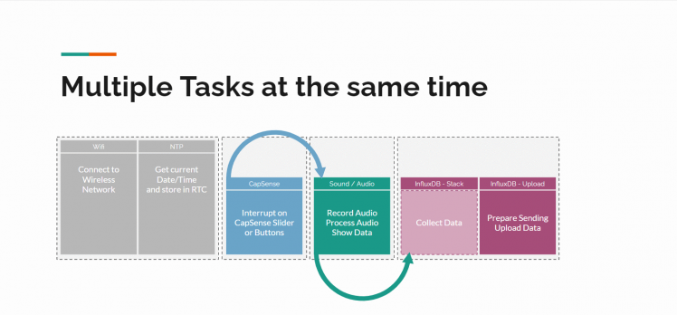
That is where Real Time Operating Systems come into play! Still the processor does 1 task at a time, but these operating systems are able to give little sub-tasks a little bit of processor time, and keep track of their states and priorities. It does offer functionality to let one task talk to another task with queues and semaphores. And tasks can suspend or resume each other. The delay() function that would cause a full system halt, is replaced by a function that halts the current task only. So a lot of clever stuff is going on here, but most important, multiple tasks can run at the same time!
One of these Real Time Operating Systems is FreeRTOS, and does support our PSoC 6 processor. So that is what will be used in this project.
Splitting our program into tasks
To make optimal use of tasks, we have to define what the tasks are that have to run in parallel.
For us that will be (also see the RTOS example picture):
- WiFi task: at startup, create a WiFi connection and receive the current datetime stamp from an NTP server, and store that in the RTC. If connection is lost, create a new connection.
- CapSense tasks: 'listen' to the CapSense slider and buttons. Once something happens, immediately publish the values to let other tasks use it.
- Audio task: get data from the microphone, do many calculations with the data and show the results
- Influx task: data collection and sending the data over TCP to the InfluxDB API when our queue/stack is full
Each task will get it's own priority, meaning FreeRTOS will decide who goes first if two tasks ask for processing time at the same moment:
- As the CapSense task has to monitor the slider/button state, these get the highest priority. On the other hand, they do not have to do a lot, so they will most time be in a dormant mode.
- Then we have the Audio Task that might consume most calculation power. And I want this to happen fast, to get to the next audio frame as quickly as possible.
- The Influx task is just collecting data, and once every so many seconds does really upload the collected data, so the priority is low.
- The WiFi task seems to need quite some priority at the moment of starting up, but once connection is created, the priority is low. That is why I've added a little trick here: it will suspend all other tasks until the connection is complete and the timestamp is processed. Then it resumes the other tasks.
Deeper into the code
Now it is time to look into the code. I'll pick some highlights per function and will skip the header files, use the download/viewer at the bottom of this page to get the full details.
main.c:
This is where we start our task management.
1: First we create the queues. See the respective data-types for details of queue contents. There is one used for the CapSense interrupt changes that is only 1 large as each new command should replace a non-processed one, and one for the communication between the Audio task and Influx task we have a queue of 200 messages as these are the audio readings and we want them all to be processed:
- capsense_command_q = xQueueCreate(SINGLE_ELEMENT_QUEUE, sizeof(capsense_command_t));
- influx_command_data_q = xQueueCreate(200, sizeof(influx_command_data_t));
2: Then we create the 4 tasks and start them. See the explanations in previous paragraph for more details of these tasks.
- xTaskCreate(capsense_task, "CapSense Task", TASK_CAPSENSE_STACK_SIZE, NULL, TASK_CAPSENSE_PRIORITY, NULL);
- xTaskCreate(audio_task, "Audio Task", TASK_AUDIO_STACK_SIZE, NULL, TASK_AUDIO_PRIORITY, NULL);
- xTaskCreate(wifi_task, "WIFI Task", TASK_WIFI_STACK_SIZE, NULL, TASK_WIFI_PRIORITY, NULL);
- xTaskCreate(influx_task, "Influx Task", TASK_INFLUX_STACK_SIZE, NULL, TASK_INFLUX_PRIORITY, NULL);
- vTaskStartScheduler();
Once the four tasks are started by the scheduler, we should never return into this part of the code. If we do return here, something went wrong and we can exit.
wifi_task.c
This file does handle the WiFi connection, and receives data from an NTP (Network Time Protocal) server through UDP (). Let's break the code into pieces.
1: Task management: let the 3 other tasks start, and suspend themselves. I've added this because my WiFi connection seems to freeze sometimes. I couldn't find why so far, but suspending everything else made it at least a little bit more reliant. If you have a tip or trick for me, let me know!
Then the FOR loop is entered. I do have that here, because this is also used in case of a disconnect. First step is suspending the other tasks if they didn't do that on their own. Then I use the WiFi_Connect_To_AP() function for getting the WiFi connection. And if that is successful, I use the NTP_Get_Time() function. If both these are successful, the other 3 tasks are started, and the WiFi Task is suspended. It will only be woken by a disconnect, which should not happen too often.
- /* wait a little bit to give the other tasks time to suspend on their own */
- vTaskDelay(pdMS_TO_TICKS(1000u));
- /* Obtain the handle of a task from its name and resume the tasks. */
- xHandle_Audio = xTaskGetHandle( "Audio Task" );
- xHandle_Influx = xTaskGetHandle( "Influx Task" );
- xHandle_CapSense = xTaskGetHandle( "CapSense Task" );
- xHandle_WIFI = xTaskGetHandle( "WIFI Task" );
- /* "Repeatedly" running part of the task; after 1 run it does suspend,
- * but a resume could wake it up, suspending other tasks temporarily */
- for(;;) {
- /* As Wifi needs full system resources to successfully start,
- * suspend all other tasks for a moment. */
- vTaskSuspend( xHandle_Audio );
- vTaskSuspend( xHandle_Influx );
- vTaskSuspend( xHandle_CapSense );
- vTaskDelay(pdMS_TO_TICKS(1000u));
- /* Connect to WiFi AP */
- if(wifi_connect_to_ap() != CY_RSLT_SUCCESS ) {
- printf("�33[91mWIFI: Failed to connect to AP.�33[mn");
- CY_ASSERT(0);
- }
- /* Get current time from NTP server and store in RTC */
- if(ntp_get_time() != CY_RSLT_SUCCESS ) {
- printf("�33[91mNTP: Failed to get current time.�33[mn");
- CY_ASSERT(0);
- }
- /* Wifi and NTP/RTC completed, now resume the tasks. */
- vTaskResume( xHandle_CapSense );
- vTaskResume( xHandle_Influx );
- vTaskDelay(pdMS_TO_TICKS(1000u));
- vTaskResume( xHandle_Audio );
- /* Wifi task can suspend now, waiting for a renewed connection attempt */
- vTaskSuspend( xHandle_WIFI );
- }
2: Connecting to the WiFi AP: based on the credentials that are entered in the wifi_task.h file, a connection is configured. There is a callback that is used to print the IP address at connection, or will start this task over when a disconnect is registered.
- /* Initialize WiFi connection manager. */
- result = cy_wcm_init(&wifi_config);
- if (result != CY_RSLT_SUCCESS) {
- printf("�33[91mWIFI: Connection Manager initialization failed!�33[mn");
- return result;
- }
- /* Set the WiFi SSID, password and security type. */
- memset(&wifi_conn_param, 0, sizeof(cy_wcm_connect_params_t));
- memset(&ip_address, 0, sizeof(cy_wcm_ip_address_t));
- memcpy(wifi_conn_param.ap_credentials.SSID, WIFI_SSID, sizeof(WIFI_SSID));
- memcpy(wifi_conn_param.ap_credentials.password, WIFI_PASSWORD, sizeof(WIFI_PASSWORD));
- wifi_conn_param.ap_credentials.security = WIFI_SECURITY_TYPE;
- /* Join the WiFi AP. */
- for(uint32_t conn_retries = 0; conn_retries < MAX_WIFI_CONN_RETRIES; conn_retries++ ) {
- result = cy_wcm_connect_ap(&wifi_conn_param, &ip_address);
- if(result == CY_RSLT_SUCCESS) {
- printf("�33[94mWIFI: Successfully connected to network '%s'.�33[mn",
- wifi_conn_param.ap_credentials.SSID);
- /* Callback event that shows disconnects and reconnects. */
- cy_wcm_register_event_callback(wifi_network_event_callback);
- /* We are successfully connected, exit the function with a success message */
- return CY_RSLT_SUCCESS;
- }
- printf("�33[91mWIFI: Connection to network failed with error code %d. Retrying in %d ms...�33[mn",
- (int)result, WIFI_CONN_RETRY_INTERVAL_MSEC);
- vTaskDelay(pdMS_TO_TICKS(WIFI_CONN_RETRY_INTERVAL_MSEC));
- }
- /* Stop retrying after maximum retry attempts. */
- printf("�33[91mWIFI: Exceeded maximum connection attempts.�33[mn");
3: Getting the NTP time: this is where I had a lot of struggles with. There are complete NTP libraries available for C++, but not an easy implementation for C. Based on snippets from here and there, and the UDP example sketch from ModusToolbox, I was able to get this working. The NTP connection creates an interrupt for receiving data. Once the interrupt happens and was able to correctly process the NTP packet into the RTC, the main class will continue.
- /* IP address and UDP port number of the UDP server */
- cy_socket_sockaddr_t udp_server_addr = {
- .ip_address.ip.v4 = NTP_SERVER_IP_ADDRESS,
- .ip_address.version = CY_SOCKET_IP_VER_V4,
- .port = NTP_SERVER_PORT
- };
- /* Prepare the NTP packet that we will send:
- * Set the first byte's bits to 01,100,011;
- * LI = 1 (01) (Leap Indicator "last minute of the day has 61 seconds",
- * ignored in request)
- * VN = 4 (100) (Version Number)
- * Mode = 3 (011) (Mode = 3: client)
- */
- memset( &packet, 0, sizeof( ntp_packet ) );
- *( ( char * ) &packet + 0 ) = 0b01100011;
- /* Sockets initialization */
- cy_socket_init();
- /* Create a UDP socket. */
- cy_socket_create(CY_SOCKET_DOMAIN_AF_INET, CY_SOCKET_TYPE_DGRAM,
- CY_SOCKET_IPPROTO_UDP, &udp_client_handle);
- /* Variable used to set socket receive callback function. */
- cy_socket_opt_callback_t udp_recv_option = {
- .callback = ntp_client_recv_handler,
- .arg = NULL};
- /* Register the callback function to handle messages received from UDP client. */
- cy_socket_setsockopt(udp_client_handle, CY_SOCKET_SOL_SOCKET, CY_SOCKET_SO_RECEIVE_CALLBACK,
- &udp_recv_option, sizeof(cy_socket_opt_callback_t));
- /* Send NTP data to Server */
- cy_socket_sendto(udp_client_handle, (char*) &packet, sizeof(ntp_packet), CY_SOCKET_FLAGS_NONE,
- &udp_server_addr, sizeof(cy_socket_sockaddr_t), &bytes_sent);
- /* When we are here, we did successfully send a message to the NTP server.
- * Now we wait for a returning message */
- for(;;) {
- if(received_time_from_server) {
- /* Return message is received and time is extracted, so jump out of the FOR loop */
- break;
- }
- vTaskDelay(RTOS_TASK_TICKS_TO_WAIT);
- }
- /* Read the time stored in the RTC */
- cyhal_rtc_read(&rtc_obj, &date_time);
- time_t t_of_day = mktime(&date_time);
- printf("�33[94mRTC: %s�33[m", asctime(&date_time));
- printf("�33[94mRTC: seconds since the Epoch: %ld�33[mn", (long) t_of_day);
- /* All done for the UDP/NTP/RTC functions! */
- /* Disconnect the UDP client. */
- cy_socket_disconnect(udp_client_handle, 0);
- /* Free the resources allocated to the socket. */
- cy_socket_delete(udp_client_handle);
Within the interrupt we handle unraveling the NTP message and storing it into the RTC:
- /* To hold the NTP time */
- struct tm * new_time = {0};
- /* Receive incoming message from UDP server. */
- result = cy_socket_recvfrom(udp_client_handle, &packet, MAX_UDP_RECV_BUFFER_SIZE,
- CY_SOCKET_FLAGS_RECVFROM_NONE, NULL, 0, &bytes_received);
- if ( bytes_received < 0 ) {
- printf( "�33[91mUDP: error reading from socket�33[mn" );
- return result;
- }
- /* These two fields contain the time-stamp seconds as the packet left the NTP server.
- * The number of seconds correspond to the seconds passed since 1900.
- * ntohl() converts the bit/byte order from the network's to host's "endianness".
- */
- packet.txTm_s = ntohl( packet.txTm_s ); // Time-stamp seconds.
- packet.txTm_f = ntohl( packet.txTm_f ); // Time-stamp fraction of a second.
- /* Extract the 32 bits that represent the time-stamp seconds (since NTP epoch)
- * from when the packet left the server.
- * Subtract 70 years worth of seconds from the seconds since 1900.
- * This leaves the seconds since the UNIX epoch of 1970.
- * (1900)------------------
- * (1970)**************************************(Time Packet Left the Server)
- */
- time_t txTm = ( time_t ) ( packet.txTm_s - NTP_TIMESTAMP_DELTA );
- /* Print the time we got from the server, in UTC time. */
- printf( "�33[94mNTP: time received: %s�33[m", ctime( ( const time_t* ) &txTm ) );
- /* Initialize RTC */
- cyhal_rtc_init(&rtc_obj);
- new_time = gmtime(&txTm);
- /* Write the time to the RTC */
- cyhal_rtc_write(&rtc_obj, new_time);
- printf("�33[94mRTC: Time updated.�33[mn");
- received_time_from_server = true;
capsense_task.c
This is where all the Slider and Button handling happens. And beside some very little changes, this actually is exactly the code from the ModusToolbox example.
The task goes into suspend mode immediately and will wait there until the WiFi connection is completed. To show that it started, print something to the debug lines.
- /* Immediately suspend the task to give WIFI connection priority */
- vTaskSuspend( NULL );
- printf("33[94mCapSense: task started!33[mn");
Then the CapSense is tuned and initialized. Ready for creating the endless FOR loop to check for changes.
- BaseType_t rtos_api_result;
- cy_status result = CY_RSLT_SUCCESS;
- capsense_command_t capsense_cmd;
- /* Initialize timer for periodic CapSense scan */
- scan_timer_handle = xTimerCreate ("Scan Timer", CAPSENSE_SCAN_INTERVAL_MS,
- pdTRUE, NULL, capsense_timer_callback);
- /* Setup communication between Tuner GUI and PSoC 6 MCU */
- tuner_init();
- /* Initialize CapSense block */
- capsense_init();
- /* Start the timer */
- xTimerStart(scan_timer_handle, 0u);
- /* Repeatedly running part of the task */
- for(;;) {
Here we use the FreeRTOS Queue function to receive data that the interrupt generated. There are two types of messages we can receive in the queue: SCAN and PROCESS. In case of the second one, the interrupt did receive updated data, so we will process that. The process does compare the previous button states, and if a difference is found, the "CapSense_slider_value" is updated with the new value. And that variable is used later on in the Audio task. This CapSense task doesn't have to do anything else. Which is a good thing and it's purpose: it should be very fast in responding to a touch of the sensor!
- /* Block until a CapSense command has been received over queue */
- rtos_api_result = xQueueReceive(capsense_command_q, &capsense_cmd,
- portMAX_DELAY);
- /* Command has been received from capsense_cmd */
- if(rtos_api_result == pdTRUE) {
- /* Check if CapSense is busy with a previous scan */
- if(CY_CAPSENSE_NOT_BUSY == Cy_CapSense_IsBusy(&cy_capsense_context)) {
- switch(capsense_cmd) {
- case CAPSENSE_SCAN:
- {
- /* Start scan */
- Cy_CapSense_ScanAllWidgets(&cy_capsense_context);
- break;
- }
- case CAPSENSE_PROCESS:
- {
- /* Process all widgets */
- Cy_CapSense_ProcessAllWidgets(&cy_capsense_context);
- process_touch();
- /* Establishes synchronized operation between the CapSense
- * middleware and the CapSense Tuner tool. */
- Cy_CapSense_RunTuner(&cy_capsense_context);
- break;
- }
- }
- }
- }
- /* Task has timed out and received no data during an interval of
- * portMAXDELAY ticks. */
- else {
- /* You could handle a timeout here */
- }
This is the actual touch processing code, which uses the Slider values to put a threshold on the LED in the audio task. Left button for is equal to minimum value (1), and Right button for maximum value (100).
- static void process_touch(void)
- {
- /* Variables used to store touch information */
- uint32_t button0_status = 0;
- uint32_t button1_status = 0;
- uint16_t slider_pos = 0;
- uint8_t slider_touched = 0;
- cy_stc_capsense_touch_t *slider_touch;
- uint32_t CapSense_slider_reading = 1;
- /* Variables used to store previous touch information */
- static uint32_t button0_status_prev = 0;
- static uint32_t button1_status_prev = 0;
- static uint16_t slider_pos_perv = 0;
- /* Get button 0 status */
- button0_status = Cy_CapSense_IsSensorActive(
- CY_CAPSENSE_BUTTON0_WDGT_ID,
- CY_CAPSENSE_BUTTON0_SNS0_ID,
- &cy_capsense_context);
- /* Get button 1 status */
- button1_status = Cy_CapSense_IsSensorActive(
- CY_CAPSENSE_BUTTON1_WDGT_ID,
- CY_CAPSENSE_BUTTON1_SNS0_ID,
- &cy_capsense_context);
- /* Get slider status */
- slider_touch = Cy_CapSense_GetTouchInfo(
- CY_CAPSENSE_LINEARSLIDER0_WDGT_ID,
- &cy_capsense_context);
- slider_pos = slider_touch->ptrPosition->x;
- slider_touched = slider_touch->numPosition;
- /* Detect new touch on Button0 */
- if((0u != button0_status) && (0u == button0_status_prev)) {
- CapSense_slider_value = 1;
- }
- /* Detect new touch on Button1 */
- if((0u != button1_status) && (0u == button1_status_prev)) {
- CapSense_slider_value = 100;
- }
- /* Detect new touch on slider */
- if((0u != slider_touched) && (slider_pos_perv != slider_pos )) {
- CapSense_slider_reading = (slider_pos * 100)
- / cy_capsense_context.ptrWdConfig[CY_CAPSENSE_LINEARSLIDER0_WDGT_ID].xResolution;
- CapSense_slider_value = (CapSense_slider_reading < 1) ? 1 : CapSense_slider_reading;
- }
- /* Update previous touch status */
- button0_status_prev = button0_status;
- button1_status_prev = button1_status;
- slider_pos_perv = slider_pos;
- }
audio_task.c
Now we get into the interesting part. All the sound recording and audio calculation functions!
For the calculation part, I've spend quite some time googling for examples. And I have to say, there is nothing right out of the box 100% working to find. On the logical order, these were good pieces of information: [Stack Overflow] and [Stack Overflow]. Then code examples, but although each with their own things that didn't tie out perfectly and that I changed in my code: [Noise Level Meter] and [LoRaSoundkit]. And I've used [ArduinoFFT], where I only used the parts needed for this project, to keep it simple to follow (and was less work to convert it into a ModusToolbox working function).
My sound input is a 44.100 Hz samples/second, resulting in 4096 data points. That means we can sample is 10.7666 Hz per step. As we can only use half of the data points for steps (2048 steps), that means we have a range of 22 kHz. We start by setting up the microphone with these settings. The decimation rate is used in the PDM to PCM conversion. The system clock hz is used to synchronize the clock speed with the pdm/pcm clocks.
- /* Define how many samples in a frame */
- #define FRAME_SIZE 4096u
- /* Desired sample rate. Typical values: 8/16/22.05/32/44.1/48 kHz */
- #define SAMPLE_RATE_HZ 44100u
- /* Decimation Rate of the PDM/PCM block. Typical value is 64. DEC_RATE = 2 x SINC_RATE */
- #define DECIMATION_RATE 64u
- /* Audio Subsystem Clock. Typical values depends on the desire sample rate:
- - 8/16/48kHz : 24.576 MHz
- - 22.05/44.1kHz : 22.574 MHz */
- #define AUDIO_SYS_CLOCK_HZ 22574000u
- const cyhal_pdm_pcm_cfg_t pdm_pcm_cfg =
- {
- .sample_rate = SAMPLE_RATE_HZ,
- .decimation_rate = DECIMATION_RATE,
- .mode = AUDIO_MODE,
- .word_length = 16, /* bits */
- .left_gain = GAIN_LEFT , /* dB */
- .right_gain = GAIN_RIGHT , /* dB */
- };
- /* Init the clocks */
- clock_init();
- /* Initialize the PDM/PCM block */
- cyhal_pdm_pcm_init(&pdm_pcm, PDM_DATA, PDM_CLK, &audio_clock, &pdm_pcm_cfg);
- cyhal_pdm_pcm_register_callback(&pdm_pcm, pdm_pcm_isr_handler, NULL);
- cyhal_pdm_pcm_enable_event(&pdm_pcm, CYHAL_PDM_PCM_ASYNC_COMPLETE, CYHAL_ISR_PRIORITY_DEFAULT, true);
- cyhal_pdm_pcm_start(&pdm_pcm);
In above code, 3rd last line, there is a callback created. That callback does happen when recording an audioframe is completed and data is available. At that moment, only the flag "pdm_pcm_flag" is set to true.
As this Audio Task will use the onboard LED to show the total dB of the last reading, we need to init that as well:
- /* Initialize a PWM resource for driving an LED. */
- cyhal_pwm_init(&pwm_led, CYBSP_USER_LED, NULL);
- cyhal_pwm_set_duty_cycle(&pwm_led, GET_DUTY_CYCLE(LED_MAX_BRIGHTNESS), PWM_LED_FREQ_HZ);
- cyhal_pwm_start(&pwm_led);
And now we get to the real fun in the FOR loop!
First step is to check if the "pdm_pcm_flag" is set. If not, it will skip all the code to the end, and waits for 1 millisecond before trying again. Using this 1 millisecond delay, gives other tasks the opportunity to do their things as well (like uploading the data to InfluxDB). When the flag is set, immediately get the RTC time so that we know when this reading happened. We use that time to compare with previous readings to see if we are still in the same second. When we jumped into the next second, first average all previous readings and stack them into the Influx queue. More on what happens there later on.
- if (pdm_pcm_flag) {
- /* Clear the PDM/PCM flag */
- pdm_pcm_flag = false;
- /* Read current time from the RTC to test of reachable*/
- cyhal_rtc_read(&rtc_obj, &date_time);
- if ((long) mktime(&date_time) > (long) mktime(&avg_date_time)) {
- /* We are in the next second, calculate averages of the previous second! */
- for ( int i = 0; i < OCTAVES; i++) {
- audio_z_avg[i] /= (float) avg_count;
- audio_a_avg[i] /= (float) avg_count;
- }
- /* calculate the dB of the averages */
- soundsensor_toDecibel(audio_z_avg, OCTAVES);
- soundsensor_toDecibel(audio_a_avg, OCTAVES);
- /* Send off the Z weighted readings to the Influx task */
- influx_cmd_data.influx_command = INFLUX_DATA;
- influx_cmd_data.audio_weighting = "z";
- influx_cmd_data.audio_octave01 = audio_z_avg[0];
- /* same happens for octave 2-11 */
- influx_cmd_data.audio_volume = audio_z_avg[OCTAVES];
- influx_cmd_data.sec_since_epoch = (long) mktime(&avg_date_time);
- xQueueSendToBack(influx_command_data_q, &influx_cmd_data, 0u);
- /* Send off the A weighted readings to the Influx task */
- /* reset the spectrum output */
- avg_count = 0;
- avg_date_time = date_time;
- for ( int i = 0; i < OCTAVES; i++) {
- audio_z_avg[i] = 0.0;
- audio_a_avg[i] = 0.0;
- }
- }
- /* Last second average completed, now process new audio data */
And yes, there it is, here is where the audio calculations happen!
- /* Convert the 16 bit integer to a float */
- soundsensor_integerToFloat(audio_frame, audio_real, audio_imag, FRAME_SIZE);
- /* apply HANN window, optimal for energy calculations */
- arduinoFFT_Windowing(FFT_WIN_TYP_HANN, FFT_FORWARD, audio_real, FRAME_SIZE);
- /* do FFT processing */
- arduinoFFT_Compute(FFT_FORWARD, audio_real, audio_imag, FRAME_SIZE);
- /* calculate energy */
- soundsensor_calculateEnergy(audio_real, audio_imag, FRAME_SIZE);
- /* sum up energy in bin for each octave */
- soundsensor_sumEnergy(audio_real, audio_energy, FRAME_SIZE, OCTAVES);
- /* update the spectrum with new measurements */
- soundsensor_loudnessWeighting(audio_energy, zWeighting, audio_z_spectrum, OCTAVES);
- soundsensor_loudnessWeighting(audio_energy, aWeighting, audio_a_spectrum, OCTAVES);
- /* Add the reading to the AVG */
- avg_count += 1;
- for ( int i = 0; i < OCTAVES; i++) {
- audio_z_avg[i] += audio_z_spectrum[i];
- audio_a_avg[i] += audio_a_spectrum[i];
- }
- /* calculate the dB */
- soundsensor_toDecibel(audio_z_spectrum, OCTAVES);
- soundsensor_toDecibel(audio_a_spectrum, OCTAVES);
As you see, these are just references to the classes where the logic happens. Let's go through them;
1: integerToFloat: Convert 16 bits from integer to float. But it turns out, our PDM/PCM doesn't store 16 bits. It only stores 8 bits. (even if we did set it up that way...) And it doesn't put these bits in the high bytes as others do, but at the low bytes. Which makes it easier! As we work with FFT in complex data, there is a REAL and IMAG part. As this is the first step, we fill in the REAL and zero the IMAG.
- void soundsensor_integerToFloat(int16_t *samples, float *vReal, float *vImag, uint16_t size) {
- int bit_size = 8;
- for (uint16_t i = 0; i < size; i++) {
- vReal[i] = (float)((samples[i] / pow(2,bit_size-1)));
- vImag[i] = 0.0;
- }
- }
2: FFT_Windowing: The floats from the previous step end up in the range between -1 and 1. For FFT we need values between 0 and 1. The HANN window works best for that, so we convert our data with that setting.
- void arduinoFFT_Windowing(uint8_t windowType, uint8_t dir, float *vReal, uint16_t size) {
- double samplesMinusOne = (double) size - 1.0;
- for (uint16_t i = 0; i < (size >> 1); i++) {
- double indexMinusOne = (double) i;
- double ratio = (indexMinusOne / samplesMinusOne);
- double weightingFactor = 1.0;
- /* Compute and record weighting factor for windowing */
- switch (windowType) {
- case FFT_WIN_TYP_HANN:
- {
- weightingFactor = 0.54 * (1.0 - cos(twoPi * ratio));
- break;
- }
- }
- if (dir == FFT_FORWARD) {
- vReal[i] *= weightingFactor;
- vReal[size - (i + 1)] *= weightingFactor;
- }
- else {
- vReal[i] /= weightingFactor;
- vReal[size - (i + 1)] /= weightingFactor;
- }
- }
- }
3: FFT_Compute: Computes in-place complex-to-complex FFT. This does the heavy complex calculations for us.
- void arduinoFFT_Compute(uint8_t dir, float *vReal, float *vImag, uint16_t size){
- /* Reverse bits */
- uint16_t j = 0;
- for (uint16_t i = 0; i < (size - 1); i++) {
- if (i < j) {
- arduinoFFT_Swap(&vReal[i], &vReal[j]);
- if(dir==FFT_REVERSE)
- arduinoFFT_Swap(&vImag[i], &vImag[j]);
- }
- uint16_t k = (size >> 1);
- while (k <= j) {
- j -= k;
- k >>= 1;
- }
- j += k;
- }
- /* Compute the FFT */
- double c1 = -1.0;
- double c2 = 0.0;
- uint16_t l2 = 1;
- for (uint8_t l = 0; (l < arduinoFFT_Exponent(size)); l++) {
- uint16_t l1 = l2;
- l2 <<= 1;
- double u1 = 1.0;
- double u2 = 0.0;
- for (j = 0; j < l1; j++) {
- for (uint16_t i = j; i < size; i += l2) {
- uint16_t i1 = i + l1;
- double t1 = u1 * vReal[i1] - u2 * vImag[i1];
- double t2 = u1 * vImag[i1] + u2 * vReal[i1];
- vReal[i1] = vReal[i] - t1;
- vImag[i1] = vImag[i] - t2;
- vReal[i] += t1;
- vImag[i] += t2;
- }
- double z = ((u1 * c1) - (u2 * c2));
- u2 = ((u1 * c2) + (u2 * c1));
- u1 = z;
- }
- c2 = sqrt((1.0 - c1) / 2.0);
- c1 = sqrt((1.0 + c1) / 2.0);
- if (dir == FFT_FORWARD) {
- c2 = -c2;
- }
- }
- /* Scaling for reverse transform */
- if (dir != FFT_FORWARD) {
- for (uint16_t i = 0; i < size; i++) {
- vReal[i] /= size;
- vImag[i] /= size;
- }
- }
- }
4: calculateEnergy: Calculates energy from Real and Imaginary parts and place it back in the Real part. Only for half of the dataset!
- void soundsensor_calculateEnergy(float *vReal, float *vImag, uint16_t size) {
- for (uint16_t i = 0; i < size/2 ; i++) {
- vReal[i] = sqrt(sq(vReal[i]) + sq(vImag[i]));
- }
- }
5: sumEnergy: Sums up energy in whole octave bins.
NOTE: octave bins are square blocks in this code, with the determined Hz value being in the middle of the block. but in real life they have curves and overlap. That isn't implemented here! That is a TODO, but would require to swap the sumEnergy and loudnessWeighting steps.
- void soundsensor_sumEnergy(const float *vReal, float *vEnergy, uint16_t size, uint16_t octaves) {
- int bin_size = 1;
- int bin = bin_size;
- for (int octave = 0; octave < octaves; octave++){
- float sum = 0.0;
- for (int i = 0; i < bin_size && bin < size/2; i++){
- sum += vReal[bin++];
- }
- vEnergy[octave] = (sum / (bin_size/2.0));
- bin_size *= 2;
- }
- }
6: loudnessWeighting: Calculates the loudness input, according to A/C/Z-weighting scale. Negative weightings don't make sense. So in that case we assume there is no sound on this level and set everything below 1 to 1.
- /* 16Hz 31.5Hz 63Hz 125Hz 250Hz 500Hz 1kHz 2kHz 4kHz 8kHz 16kHz */
- static float aWeighting[] = { -56.7, -39.4, -26.2, -16.1, -8.6, -3.2, 0.0, 1.2, 1.0, -1.1, -6.6 };
- static float cWeighting[] = { -8.5, -3.0, -0.8, -0.2, 0.0, 0.0, 0.0, -0.2, -0.8, -3.0, -8.5 };
- static float zWeighting[] = { 0.0, 0.0, 0.0, 0.0, 0.0, 0.0, 0.0, 0.0, 0.0, 0.0, 0.0 };
- void soundsensor_loudnessWeighting(float *vEnergy, float *weighting, float *spectrum, uint16_t octaves) {
- float calc_energy = 0.0;
- for (int i = 0; i < octaves; i++) {
- calc_energy = vEnergy[i] * sqrt(pow(10, weighting[i] / 10.0));
- spectrum[i] = (calc_energy > 1 ? calc_energy : 1);
- } }
7: toDecibel: Almost there! We now convert our readings into Decibels (dB) for each octave bin. There is also calculated a dB for the total and stored in an extra bit of the spectrum. If in the calculateEnergy() step, we didn't SQRT vReal it would be 10*log10(). But we did SQRT the value there, so we need to use 20*log10() here
- void soundsensor_toDecibel(float *spectrum, uint16_t octaves) {
- float full_spectrum = 0.0;
- /* calculate for each octave the dB */
- for ( int i = 0; i < octaves; i++) {
- full_spectrum += spectrum[i];
- spectrum[i] = 20.0 * log10(spectrum[i]);
- }
- /* this is the total over all octaves */
- spectrum[octaves] = 20.0 * log10(full_spectrum);
- }
That was all the special calculations applied. What is left, is printing the results to a terminal for a direct view of the sound/audio measurements.
- /* Print the spectrum dB values from the A-Weighting.
- * Skip the 16Hz bin as we cannot hear that anyway */
- for (int i = 1; i < OCTAVES; i++) {
- printf(" %8.1f", audio_a_spectrum[i]);
- }
- /* Print the total dB value */
- printf(" %8.1f ", audio_a_spectrum[OCTAVES]);
- /* Create a bar to show the total dB values, divided by 10 to keep it readable.
- * Range is up to 150, which means you will be deaf by that time... */
- printf("[�33[93m"); /* foreground color to "Bright Yellow" */
- for (int index = 0; index < 15; index++) {
- printf("%s", (index < floor(audio_a_spectrum[OCTAVES]/10) ? "=" : " "));
- }
- printf("�33[m]"); /* reset background color to standard */
And we present the total volume on the LED, where the CapSense slider value is used for a threshold.
- /* Calculate the brightness of the LED */
- corrected_volume = floor(audio_a_spectrum[OCTAVES]) > CapSense_slider_value ? (uint32_t) floor(audio_a_spectrum[OCTAVES]) - CapSense_slider_value : 0;
- if (corrected_volume <= 0) {
- /* Stop PWM to turn the LED off */
- cyhal_pwm_stop(&pwm_led);
- }
- else {
- /* make sure the LED brightness is between the MIN and MAX */
- corrected_volume = corrected_volume < LED_MIN_BRIGHTNESS ? LED_MIN_BRIGHTNESS : corrected_volume;
- corrected_volume = corrected_volume > LED_MAX_BRIGHTNESS ? LED_MAX_BRIGHTNESS : corrected_volume;
- /* Start PWM to turn the LED on and drive the LED with brightness */
- cyhal_pwm_set_duty_cycle(&pwm_led, GET_DUTY_CYCLE(corrected_volume), PWM_LED_FREQ_HZ);
- cyhal_pwm_start(&pwm_led);
- }
And last but not least, instruct our PDM microphone to record us another sample!
- /* Read the next audio frame */
- cyhal_pdm_pcm_read_async(&pdm_pcm, audio_frame, FRAME_SIZE);
That is all we need inside the audio task at this moment.
I have ideas to enhance it further, mainly on how the octaves are calculated (change that to octave-bands), and how the weighting is done based on full octaves, and not the precise values.
influx_task.c
Last part of the code, and as there are some repeating tricks, I will skip some of them.
This task is used for stacking the queued data, and process it when there are several in the queue. I've chosen to collect 20 readings, both A and Z together. As there was averaged per second, that means this contains 10 seconds of data. If you are not looking live at the graphs, you could collect for a longer time, but be aware of memory overflow issues.
For the InfluxDB data, the API expects us to deliver something like this:
- POST http://192.1668.1.245:9999/api/v2/write?org=MyFlux&bucket=AudioSensor&precision=s HTTP/1.0
- Authorization: Token 541556ad4t56we455h41er566y744543653y41h56h4r
- Content-Type: text/plain
- Content-Length: 4012
- PSoc6,sensor=audio,weighting=a tot=23.5,oct01=0.2,oct02=3.7,oct03=4.2,oct04=12.1,oct05=13.5,oct06=15.1,oct07=12.8,oct08=11.7,oct09=8.6,oct10=5.2,oct11=0.9 1611864129
- PSoc6,sensor=audio,weighting=z tot=23.5,oct01=0.2,oct02=3.7,oct03=4.2,oct04=12.1,oct05=13.5,oct06=15.1,oct07=12.8,oct08=11.7,oct09=8.6,oct10=5.2,oct11=0.9 1611864129
- PSoc6,sensor=audio,weighting=a tot=23.5,oct01=0.2,oct02=3.7,oct03=4.2,oct04=12.1,oct05=13.5,oct06=15.1,oct07=12.8,oct08=11.7,oct09=8.6,oct10=5.2,oct11=0.9 1611864130
- PSoc6,sensor=audio,weighting=z tot=23.5,oct01=0.2,oct02=3.7,oct03=4.2,oct04=12.1,oct05=13.5,oct06=15.1,oct07=12.8,oct08=11.7,oct09=8.6,oct10=5.2,oct11=0.9 1611864130
As you see, there is one line for the A-weighting, and one line for Z-weighting, with the same epoch timestamp at the end of the line. And that it repeats 1 second up each time. I have a field called sensor=audio, which is there in preparation for if I want to upload something additionally, for example the thermistor data from this board.
The way how I'm this merging data here, is not proper programming. The compiler even gives me a warning of it. But as it works with keeping possible memory overflows in mind, I've left it as is for now. If you have a good example of how to solve this, let me know!
- /*empty the buffers at start */
- tx_buffer[0] = '�';
- tx_body[0] = '�';
- /* Empty the queue before starting */
- xQueueReset( influx_command_data_q );
- /* Set the start of the loop to -4, as first couple of audio readings have an invalid data reading */
- int i_upload = -4;
- /* Repeatedly running part of the task */
- for(;;) {
- /* Block until a command has been received over queue */
- rtos_api_result = xQueueReceive(influx_command_data_q, &influx_cmd_data, portMAX_DELAY);
- /* Command has been received from queue */
- if(rtos_api_result == pdTRUE) {
- switch(influx_cmd_data.influx_command) {
- /* Check the command and process the steps for it. */
- case INFLUX_DATA:
- {
- /* InfluxDB API data line */
- sprintf(tx_body,
- "%sPSoc6,sensor=audio,weighting=%s tot=%.1f,oct01=%.1f,oct02=%.1f,oct03=%.1f,oct04=%.1f,oct05=%.1f,oct06=%.1f,oct07=%.1f,oct08=%.1f,oct09=%.1f,oct10=%.1f,oct11=%.1f %ld",
- tx_body, influx_cmd_data.audio_weighting,
- influx_cmd_data.audio_volume, influx_cmd_data.audio_octave01, influx_cmd_data.audio_octave02, influx_cmd_data.audio_octave03, influx_cmd_data.audio_octave04, influx_cmd_data.audio_octave05, influx_cmd_data.audio_octave06, influx_cmd_data.audio_octave07, influx_cmd_data.audio_octave08, influx_cmd_data.audio_octave09, influx_cmd_data.audio_octave10, influx_cmd_data.audio_octave11,
- influx_cmd_data.sec_since_epoch);
- /* At 20, we are going to upload! (2 spectrums per second,
- * so this is 10 seconds of data) */
- if (i_upload == 20) {
- /* InfluxDB API header line */
- tx_buffer[0] = '�';
- sprintf(tx_buffer,
- "POST /api/v2/write?org=%s&bucket=%s&precision=%s HTTP/1.0rnAuthorization: Token %srnContent-Type: text/plainrnContent-Length: %drnrn%s",
- INFLUX_ORGANISATION, INFLUX_BUCKET, INFLUX_PRECISSION, INFLUX_TOKEN, strlen(tx_body), tx_body);
- result = tcp_send_to_server(tcp_server_address, tx_buffer);
- if (result == CY_RSLT_SUCCESS) {
- tx_body[0] = '�';
- }
- i_upload = 0;
- }
- /* Above 0, we assume this is just a reading to be added to previous readings */
- else if (i_upload >= 0) {
- sprintf(tx_body, "%sn", tx_body);
- i_upload++;
- }
- /* Below 0, this is a reading just after start, ignore it! */
- else {
- tx_body[0] = '�';
- i_upload++;
- }
- break;
- }
- }
- }
- /* delay for a very short time, to let the other tasks go ahead */
- vTaskDelay(pdMS_TO_TICKS(1u));
- }
At the count of 20, the package is handed over to the function to actually send the package:
- for(uint32_t conn_retries = 0; conn_retries < MAX_TCP_SERVER_CONN_RETRIES; conn_retries++) {
- /* Initialize the Sockets Library. */
- cy_socket_init();
- /* Create a new TCP socket. */
- cy_socket_create(CY_SOCKET_DOMAIN_AF_INET, CY_SOCKET_TYPE_STREAM,
- CY_SOCKET_IPPROTO_TCP, &tcp_socket_handle);
- /* Set the SEND timeout to 3000 milliseconds */
- cy_socket_setsockopt(tcp_socket_handle, CY_SOCKET_SOL_SOCKET,
- CY_SOCKET_SO_SNDTIMEO, 3000, sizeof(3000));
- /* Set the RECEIVE timeout to 5000 milliseconds */
- cy_socket_setsockopt(tcp_socket_handle, CY_SOCKET_SOL_SOCKET,
- CY_SOCKET_SO_RCVTIMEO, 5000, sizeof(5000));
- /* No need for a receive callback */
- /* No need for a disconnection callback */
- result = cy_socket_connect(tcp_socket_handle, &tcp_server_address,
- sizeof(cy_socket_sockaddr_t));
- if (result == CY_RSLT_SUCCESS) {
- /* Send a message to the TCP server. */
- conn_result = cy_socket_send(tcp_socket_handle, tx_buffer,
- strlen(tx_buffer), CY_SOCKET_FLAGS_NONE, &bytes_sent);
- if (conn_result == CY_RSLT_SUCCESS) {
- printf("�33[32mTCP: sent %ld bytes to InfluxDB server.�33[mn",
- bytes_sent);
- }
- /* Disconnect the TCP client. */
- cy_socket_disconnect(tcp_socket_handle, 0);
- /* Free the resources allocated to the socket. */
- cy_socket_delete(tcp_socket_handle);
- return conn_result;
- }
- printf("�33[91mTCP: Could not connect to TCP server. Trying to reconnect...�33[mn");
- /* The resources allocated during the socket creation (cy_socket_create)
- * should be deleted. */
- cy_socket_delete(tcp_socket_handle);
- }
Once we are able to run this, data is being uploaded to InfluxDB.
InfluxDB and Grafana
For my home automation data logger, I do use InfluxDB because it is a time scale database. For example a normal relational database like Microsoft SQL Server, MySQL, etc, is designed to store data in multiple customized tables that you can link together. You can write your custom SQL code to get the data out. Perfect for the Content Management System of your website, or to store your financial administration. But for storing sensor readings, we are not interested in all that customization. We want something that can very fast read data for a given period of time. And it should now how to get weighted averages, sums, min/max values. And that is where a database like InfluxDB is good at. You can host it on a relatively simple system, even on a Raspberry Pi (but keep in mind that a database does a lot of read/write actions and will wear out your SD card).
In the examples here, I use InfluxDB 2.0.0, which was not official yet at time of install, and had many changes in the current version. For example the port of my server is different from the current standard. It is very easy to install, and I recommend you to follow the documentation from Influx.
In older InfluxDB versions, the graphing tools were very simple and not really nice to look at. Usually I use it to see if the data is good, and I build my queries with it. For example this is the graph of A-weighted data. But as it is all 10 octaves at the same time, it looks quite messy.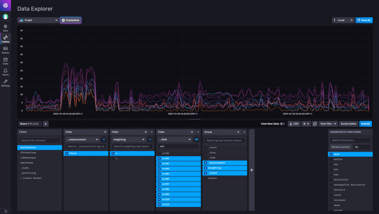
For advanced graphs and dashboards, I do use Grafana. The two products are very tied together in available functionality. Again, I recommend to follow the Grafana documentation for installing it. In this example, I've split the graphs per octave, and now you can better see in which octave more sound is registered: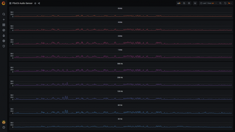
In the video for this project, I do go deeper into using and reading the graphs. So watch that ;)
But what can you do with this?
Good question! In the program that is here today, you can Analyze, Learn, Play with sound/audio data. But what more can you do with it? First some enhancement ideas, then some usage ideas.
Simple enhancement: Averaging
The PDM/PCM output is at a very detailed level (multiple readings per second), which is too much detail to be useful. I do already average the data to the second, but probably an even wider average would help:
- Smooth out sudden peaks/dips.
- Reduce the amount of data to send over WiFi, resulting in less power consumption.
- Store less datapoints on our InfluxDB, which will make it faster to analyze.
As you might have seen on the InfluxDB/Grafana dashboards, I did add an averaging function there for 5 seconds to get the smoother lines. But that is after publishing the data, and doesn't give less WiFi power consumption and less datapoints.
Advanced enhancement: Octaves & Weighting
My octaves are square blocks with the octave Hz roughly in the middle. Official octaves-bands have curves and overlap. The weighting is applied based on these whole octaves, which are an equal sum of a lot of readings, and thus miss out detail.
- By first applying the weighting formula to the detailed readings
- And then applying the octave-band formula to bin them into octaves
- The outcome would become more realistic
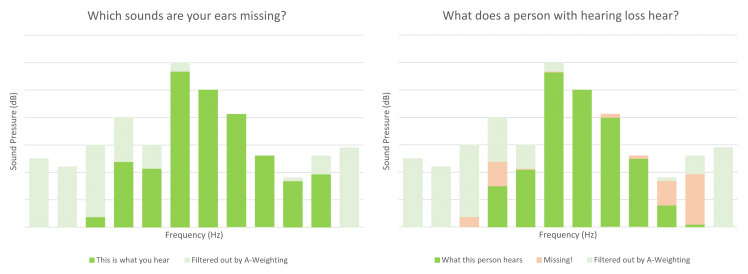
Usage: weighting data in real life
As I store both original and A-Weighted data, next is to visualize the sounds our ears are not able to hear. And for people with hearing loss, you can create custom Weighting models. Then you can tell (or warn!) what they are missing compared to others.
Did I hear ideas, questions, anything else?
The project has a working result, I'm satisfied with what I achieved. And I did learn an enormous amount of new things about sound, audio, ears, microphones, Fourier Transforms and much much more.
Credits go to all these pages that did help me getting to understand parts of it, summing together to this project. I've read so many pages, that I'm I did forgot some of them to list here.
Information about Sound, Audio and processing it:
- Wikipedia:
- NIH: Journey of Sound to the Brain
- NTI-audio: Frequency-Weightings for Sound Level Measurements
- 3Blue1Brown: What is the Fourier Transform? A visual introduction
- Steve L. Brunton: Fourier Analysis series
- Elan Ness-Cohn : Developing An Intuition for Fourier Transforms
- Stack Overflow: here and here
Technical information and code examples:
- FreeRTOS: Tasks and Queues
- Cypress documentation:
- WiFi Connection Manager Library
- Secure Sockets
- Hardware Abstraction Layer (for PDM/PCM, RTC)
- Ed Boel: Noice Level Meter
- TTNApeldoorn: LoRaSoundkit
- Enrique Condes: arduinoFFT
- David Lettier: NTP client
- Nicolas Seriot: NTP datagram
- Wikipedia: ASCI escape codes
- InfluxDB: Write data with the InfluxDB API
But that doesn't mean I'm done with it. I will make changes and enhancements. And if you have questions or additions, I'm happy to have a look at what you are doing and think along with you!
Code
Credits
bastiaanslee
Tinkerer in the field of Home Automation, with the main goal: fun! Playing with Raspberry Pi, Python, EmonCMS, meter reading, OpenTherm, Weather Station, IoT, cloud-server, Pebble Time, LoRaWAN, WeMos, InfluxDB, Grafana,NodeRed, Google Assistant, 3D Printing (Snapmaker2)

Leave your feedback...