
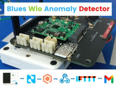
Predictive Maintenance With Blues Notecard And Wio Terminal
Made by pradeeplogu0 / Environmental Sensing / Fire & Pyrotechnics / Notifications / Productivity / IoT
About the project
Will guide you to build a cellular based predictive maintenance monitoring device with Blues Notecard, Edge Impulse, Qubitro & Wio Terminal.
Project info
Difficulty: Moderate
Platforms: Seeed Studio, Edge Impulse, Blues Wireless
Estimated time: 2 hours
License: GNU Lesser General Public License version 3 or later (LGPL3+)
Items used in this project
Hardware components

Story
In Industry 4.0, most industries are automated, and they can realize more than 200%productivity improvements.

Let’s take an example. I think this one is a good example for the industry of automation.

You well know this man, the real life Iron Man, Elon Musk. He tweeted that his Tesla factory is 75% automated. That seems like good news, right? But who cares? Everyone wants a 100% perfect product. If a system did something wrong, that means the whole process will be useless, and it affects the TTM (Time to Market) of the product. This is not only for the automotive industry, it’s the same for all industries.
So we need to ensure a system that works 24/7/365. But we want to reduce human error in the process, which is why we choose automation, but now we need humans to guarantee the system process.

Machine Learning Has played a significant role in optimizing manufacturing processes. Manufacturing companies can achieve what is called ”smart factories” by optimizing systems in factories to work with ML.
Smart factories monitor and collect production data continuously using smart devices, machines, and systems. Manufacturers can make better decisions based on advanced analytics provided by this data collection.
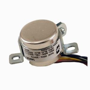
In this tutorial, I’m going to show you how to monitor industrial motor activity continuously and if the machine stops or any anomaly is detected, it will trigger an email alert.
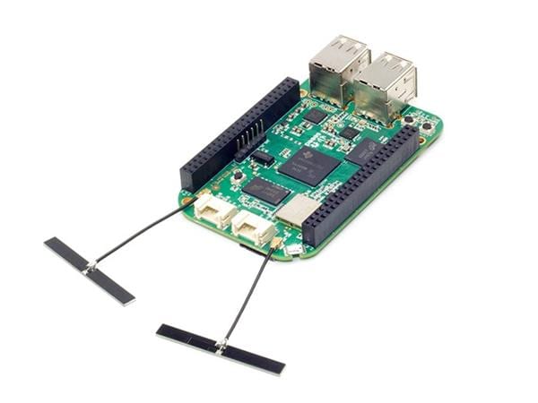
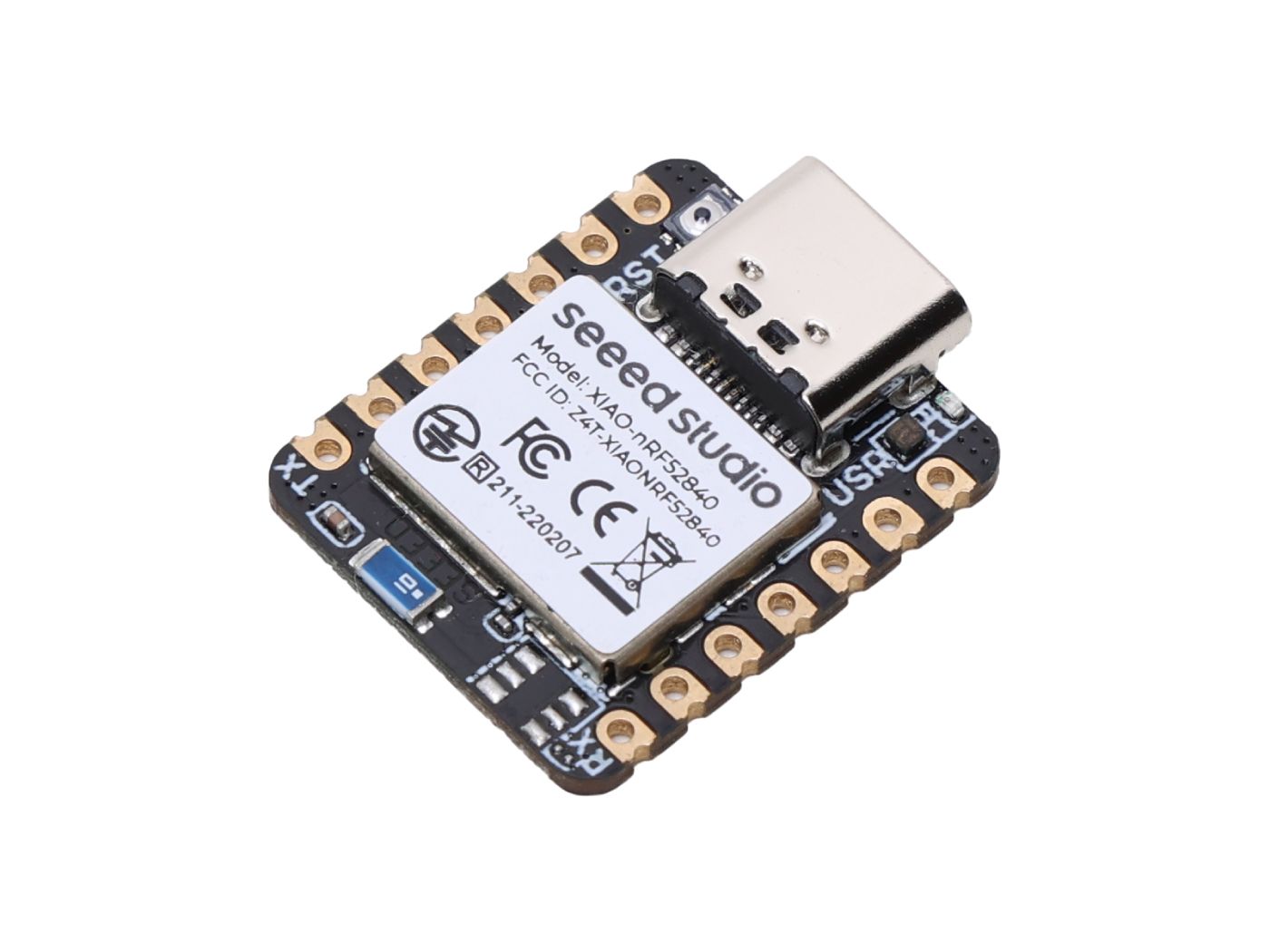
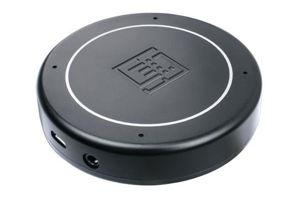
Hardware Requirements:
Software:
Flow Diagram:
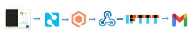
With this flow, we will first collect accelerometer data from the Wio Terminal, and then use Edge Impulse to classify anomalies. In the event of an anomaly being detected, the Blues Wireless Notecard will send the data to Notehub.io, which can then be forwarded to Qubitro via MQTT, and finally by using Webhooks, IFTTT will be used to trigger an email alert.
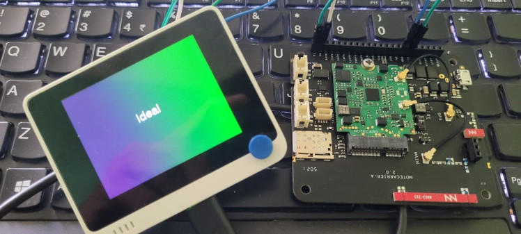
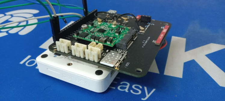
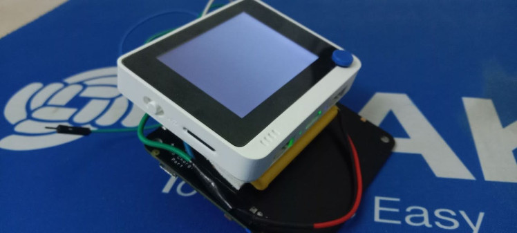
Hardware Connection:
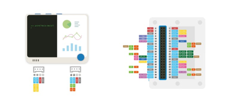
Connect the Blues Notecard’s Tx pin to Rx (pin 10), Rx to Tx (pin8) and connect +5V and Gnd pin to the Wio Terminal.
Edge Impulse Model Classification:
First connect the Wio terminal with the PC and go to https://ide.tinkergen.com/
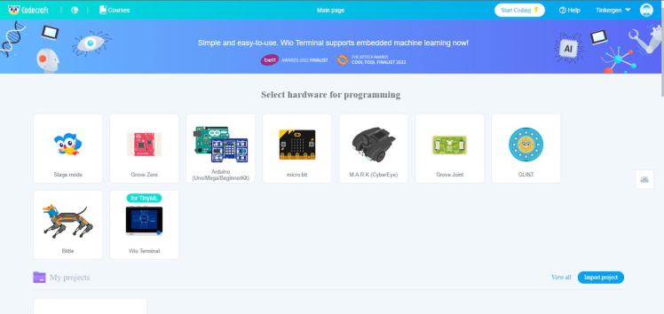
Once you open the IDE, select the device as Wio Terminal.
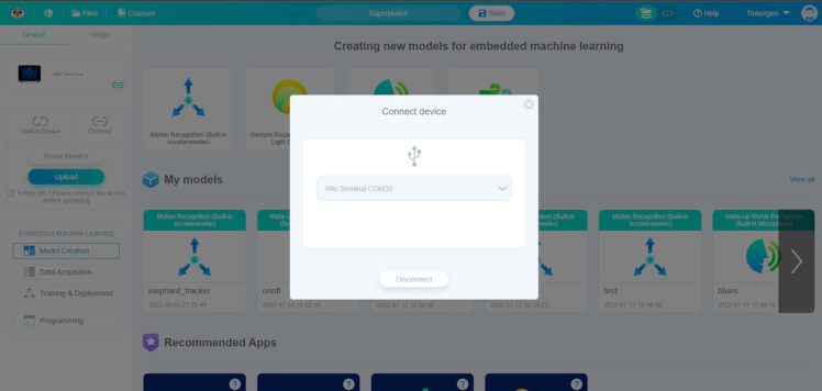
Next, select Motion data uploader.
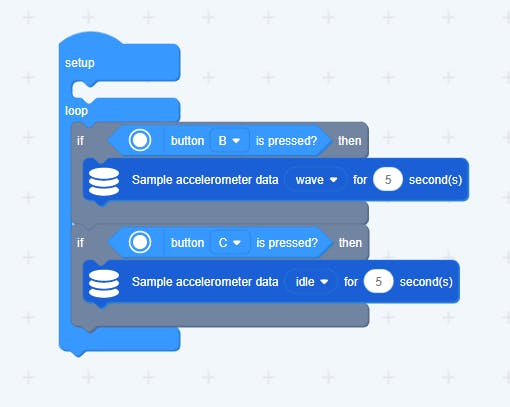
This is where you can choose or change the labels for the data. It is a default code that is used to get three different data points from the accelerometer on the Wio Terminal. As part of this project, I have used two types of data, one of which is “Ideal” and the other is “Wave”.
To upload this code to Wio Terminal, click on upload.
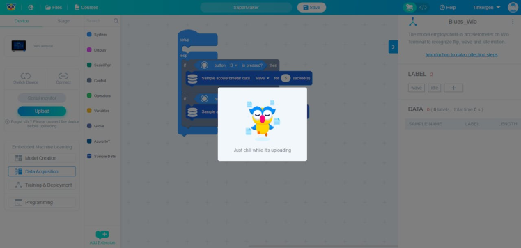
You will see this page after uploading.
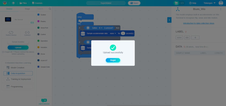
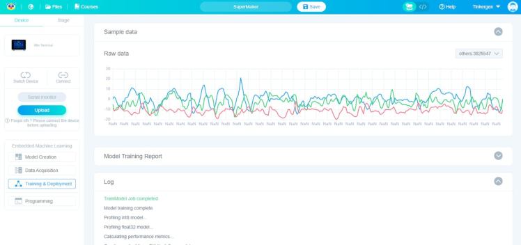
Once you click the button on the Wio Terminal, the data will be collected. Once the data has been collected, click on “Training and Classification”.

Then click the start training button. The log can be viewed after the job has been completed.
Click on the deployment option next.

Upon completion of development, you will be redirected to the programming area.
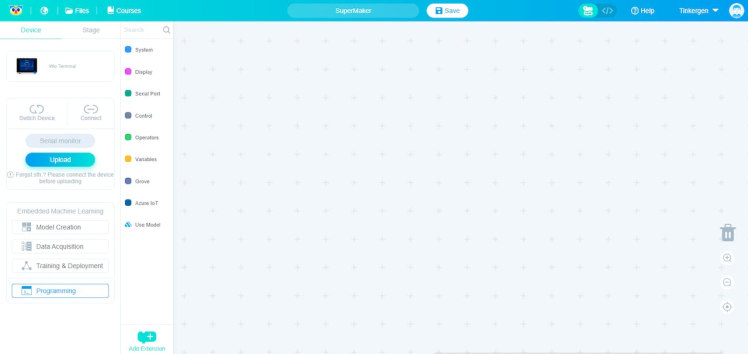
This is a simple block that will classify the data and show it on the Wio Terminal screen.
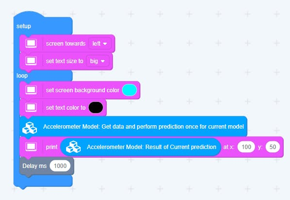

You can see the Wio Terminal response once the code has been uploaded. We now need to integrate the Blues Wireless Notecard with Wio Terminal. Just click on the code icon, and it will show the respective code. You can just copy it, as next step will require this information.
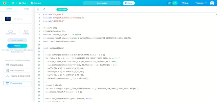
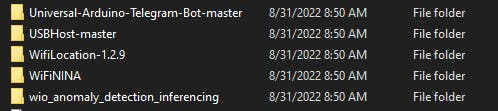
In order to add this model classification library to the Arduino IDE, you must copy and paste it into the Arduino library folder.
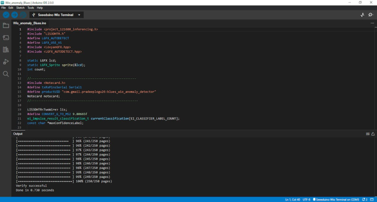
We are now ready to begin Arduino development.
Blues Wireless Notecard Integration:
Copy the code from the Tinkergen IDE and paste it, to make sure it works.
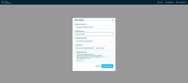
Create a new project in Notehub.io and copy the provided project ID, and replace it with the following code.
I've included Blues Wireless Notecard settings in this code, and it will send out a notification if it finds any anomalies three times.
#include <project_121680_inferencing.h>
#include "LIS3DHTR.h"
#define LGFX_AUTODETECT
#define LGFX_USE_V1
#include <Notecard.h>
#include <LGFX_AUTODETECT.hpp>
#include <LovyanGFX.hpp>
#define txRxPinsSerial Serial1
#define productUID "XXXXXXXXXXXXXXXXX"
Notecard notecard;
static LGFX lcd;
static LGFX_Sprite sprite(&lcd);
int count;
int count1;
LIS3DHTR<TwoWire> lis;
#define CONVERT_G_TO_MS2 9.80665f
ei_impulse_result_classification_t
currentClassification[EI_CLASSIFIER_LABEL_COUNT];
const char *maxConfidenceLabel;
void runClassifier() {
float buffer[EI_CLASSIFIER_DSP_INPUT_FRAME_SIZE] = {0};
for (size_t ix = 0; ix < EI_CLASSIFIER_DSP_INPUT_FRAME_SIZE; ix += 3) {
uint64_t next_tick = micros() + (EI_CLASSIFIER_INTERVAL_MS * 1000);
lis.getAcceleration(&buffer[ix], &buffer[ix + 1], &buffer[ix + 2]);
buffer[ix + 0] *= CONVERT_G_TO_MS2;
buffer[ix + 1] *= CONVERT_G_TO_MS2;
buffer[ix + 2] *= CONVERT_G_TO_MS2;
delayMicroseconds(next_tick - micros());
}
signal_t signal;
int err = numpy::signal_from_buffer(
buffer, EI_CLASSIFIER_DSP_INPUT_FRAME_SIZE, &signal);
ei_impulse_result_t result = {0};
err = run_classifier(&signal, &result, false);
float maxValue = 0;
for (size_t ix = 0; ix < EI_CLASSIFIER_LABEL_COUNT; ix++) {
ei_impulse_result_classification_t classification_t =
result.classification[ix];
ei_printf(" %s: %.5fn", classification_t.label, classification_t.value);
float value = classification_t.value;
if (value > maxValue) {
maxValue = value;
maxConfidenceLabel = classification_t.label;
}
currentClassification[ix] = classification_t;
}
}
void setup() {
lcd.init();
lcd.setRotation(1);
lis.begin(Wire1);
lis.setOutputDataRate(LIS3DHTR_DATARATE_100HZ);
lis.setFullScaleRange(LIS3DHTR_RANGE_4G);
Serial.begin(115200);
notecard.begin(txRxPinsSerial, 9600);
J *req = notecard.newRequest("hub.set");
JAddStringToObject(req, "product", productUID);
JAddStringToObject(req, "mode", "continuous");
notecard.sendRequest(req);
delay(1000);
}
void loop() {
lcd.fillScreen(0x008000u);
lcd.setFont(&fonts::Font4);
runClassifier();
lcd.setTextColor(0xFFFFFFu);
lcd.drawString((String)maxConfidenceLabel, 130, 100);
delay(500);
lcd.fillScreen(0x000000);
if (maxConfidenceLabel == "wave") {
count = count + 1;
if (count == 3) {
for (int i = 0; i <= 5; i++) {
lcd.setTextColor(0xFFFFFFu);
lcd.fillScreen(0xFF0000u);
lcd.drawString("-Alert Initiated-", 80, 100);
delay(100);
lcd.fillScreen(0x0000FFu);
lcd.setTextColor(0xFFFFFFu);
lcd.drawString("-Alert Initiated-", 80, 100);
delay(100);
}
J *req = notecard.newRequest("note.add");
if (req != NULL) {
JAddStringToObject(req, "file", "sensors.qo");
JAddBoolToObject(req, "sync", true);
J *body = JCreateObject();
if (body != NULL) {
JAddNumberToObject(body, "Anomaly_Score", 100);
JAddStringToObject(body, "Status", "Anomaly Detected");
JAddItemToObject(req, "body", body);
}
notecard.sendRequest(req);
}
Serial.println("Anomaly Detected");
lcd.fillScreen(0x000000);
count = 0;
}
}
if (maxConfidenceLabel == "Ideal") {
count1 = count1 + 1;
if (count1 == 20) {
J *req = notecard.newRequest("note.add");
if (req != NULL) {
JAddStringToObject(req, "file", "sensors.qo");
JAddBoolToObject(req, "sync", true);
J *body = JCreateObject();
if (body != NULL) {
JAddNumberToObject(body, "Anomaly_Score", 0);
JAddStringToObject(body, "Status", "No Anomaly");
JAddItemToObject(req, "body", body);
}
notecard.sendRequest(req);
}
count1 = 0;
Serial.println("No Anomaly Detected");
}
}
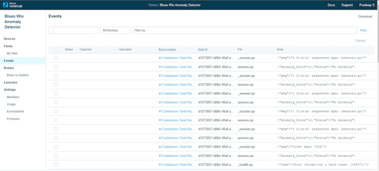
Serial.println("------------------------------------------------");
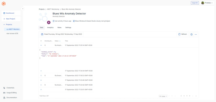
}Let's go to the events tab right away in Notehub.io and check out the incoming data.
Cloud Data Routing:
The next stage is to add a notification action, thus first we must use MQTT communication to route this data from Notehub.io to Qubitro. After that, navigate to the Device’s environment variables and set the “_sn” variable to make sure the device data is sent to the MQTT endpoint correctly.

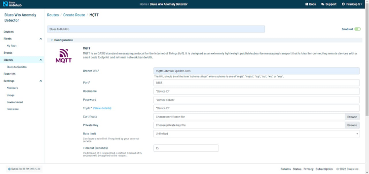
Go to the route section of Notehub.io, choose MQTT, and then initiate a new MQTT route. Copy the credentials, and then paste them in the format shown below.
Finally, scroll down and choose to transform the JSON data on the fly with a JSONata expression, since you only require a specific set of anomalous data.
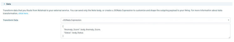
I only used the above expression since I'm utilizing this to obtain an Anomaly Score and an Anomaly status in this case.
[Refer to this Blues forum discussion for more information if necessary. https://discuss.blues.io/t/blues-mqtt-setup-with-qubitro/992]
Next, open the Qubitro portal and read the JSON data again.
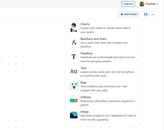
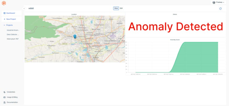
Navigate to the monitoring section, and you can add display widgets as per your needs.
Here is my sample Dashboard.
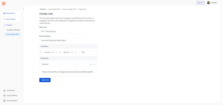
The next step is to add rules. You can add rules such as creating an alert whenever an anomaly is detected Qubitro will send data to IFTTT by using Webhooks, and we can add email triggers in IFTTT.
IFTTT Rule Setup:
Next, just go to https://ifttt.com/explore then click on create new.
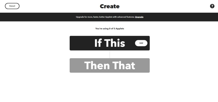
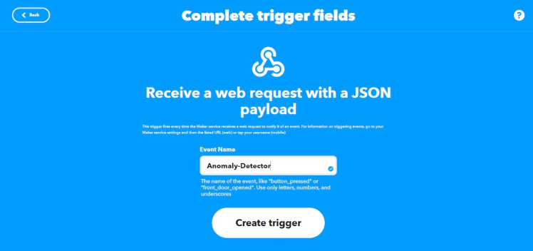
Search for trigger type as webhook, then select “Receive Web request as JSON payload”. Enter the action name.
After that, add your alert messages and choose action as your email service.
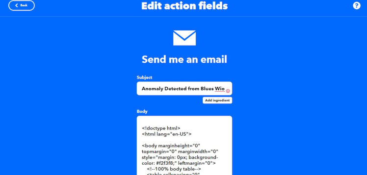
This is an example HTML email template.
Then, select connect.
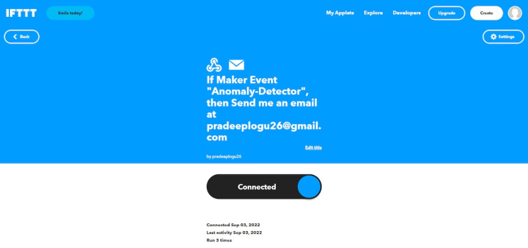
After that, go to https://ifttt.com/maker_webhooks and click on "Documentation." The personal key and webhook URL will then be displayed.
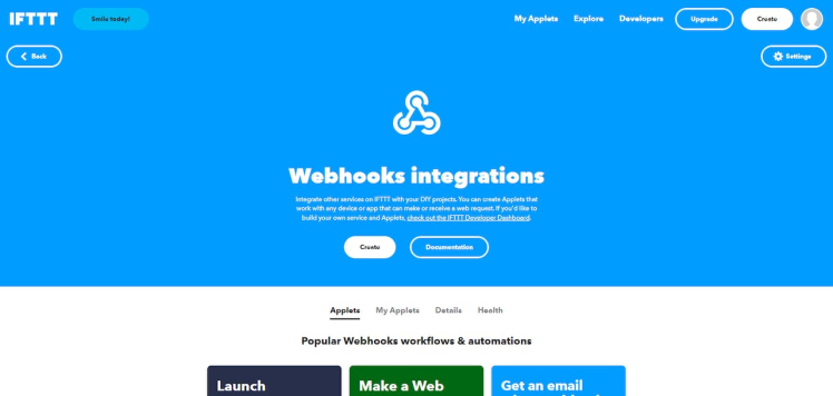
The webhook test page can be found here.
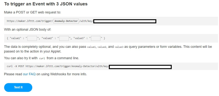
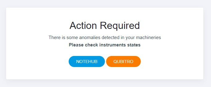
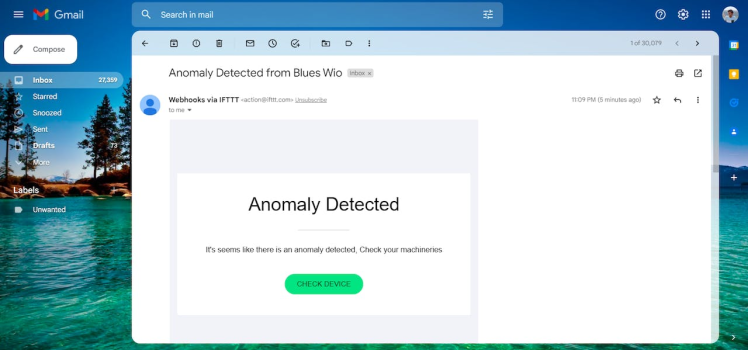
Then click Test it and wait for an email.
Navigate to the Qubitro portal, then go to the rule section, where you can add a new rule and set a rule (such as Score as 100) to be triggered whenever the anomaly score is 100.
Make Rule Setup:
In addition, I've added another automater called Make https://eu1.make.com/, to which you can add your own trigger actions.
Once logged in to Make, go to the scenarios tab and create a new scenario.
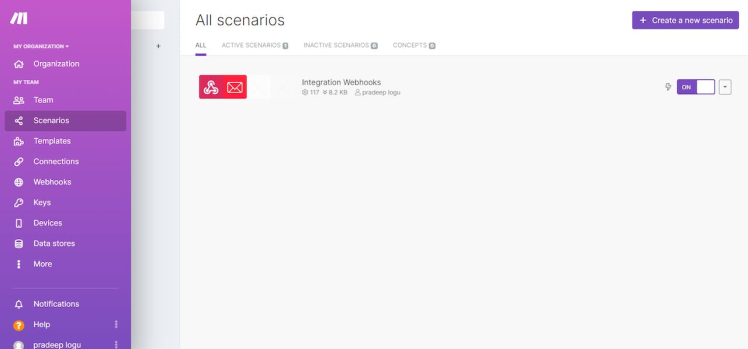
Configure a Webhook trigger and email action setup according to your needs.
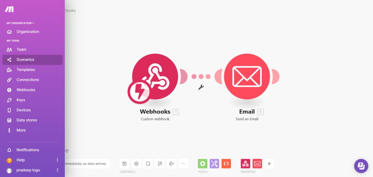
Here is my final email setup.

Conclusion:
I've just demonstrated how to create an anomaly detection system using the Blues Wireless Notecard and Seeed Studio Hardware along with Qubitro and other services in this article. You can now use ML to monitor the condition of your industrial system.
Credits
Related products


Leave your feedback...