
Pov Cylinder With Arduino Due

Made by electrouser856 / Displays / Lights
About the project
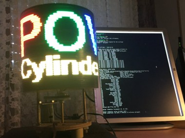
The device displays animated GIF pictures on a rotating cylinder. The GIF pictures can be downloaded from a PC via Bluetooth.
Project info
Difficulty: Difficult
Platforms: Arduino, Atmel, Microsoft, Texas Instruments
Estimated time: 1 month
License: MIT license (MIT)
Items used in this project
Hardware components


View all
Software apps and online services
Hand tools and fabrication machines
Story
Introduction
This is my first Arduino project. My work was inspired by several maker projects that created Persistence of Vision Displays [2,3,4].
Persistence of vision (POV) refers to the optical illusion whereby multiple discrete images blend into a single image in the human mind and believed to be the explanation for motion perception in cinema and animated films [1].
The projects [2,3,4] implement POV globe displays, using discrete LEDs and discrete shift registers. Instead my device is using a rotating cylinder and off-the-shelf RGB LED strips as POV Display.
The main features of my POV Cylinder are:
- POV (Persistence of Vision) Display
- Displays animated GIF pictures on a rotating cylinder
- The GIF pictures are stored in Arduino's RAM or Flash
- Communication with PC via Bluetooth
Technical Overview
- Cylinder Diameter: 200 mm
- Cylinder Height: 200 mm
- Cylinder material: Styrofoam
- Cylinder weight: 420 g
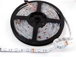
- 4 RGB LED Strips based on LPD8806
- Screen size 151 x 40 pixels
- Based on Arduino Due
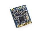
- Includes HC06 Bluetooth module
- Controlled via Bluetooth from a PC
Mechanical Construction
The mechanical construction is shown in the drawing below.
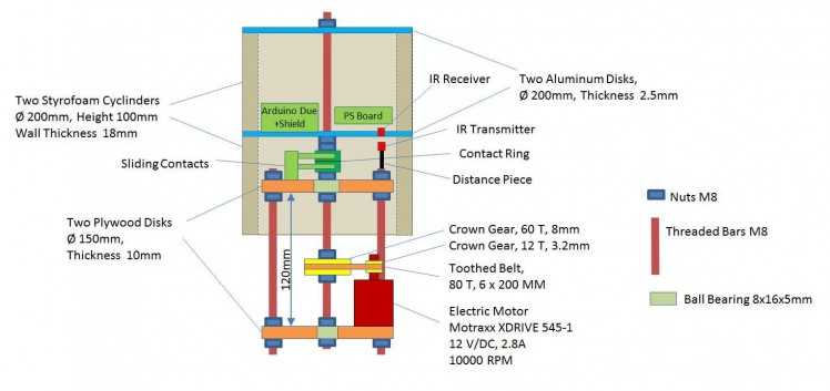 Mechanical Construction (not to scale)
The device comprises a chassis and a rotor. The chassis consists of two circular plywood disks which are connected via three threaded bars. The distance between the disks is 120 mm. In the middle there are two ball bearings and the shaft. For the shaft also a threaded bar is used. The shaft is driven by an electric motor via two crown gears and a toothed belt. The rotation speed is up to 1300 RPM (22 Hz).
The rotor consists of two styrofoam cylinders and two circular aluminium disks. The styrofoam cylinders are glued to the lower disk. The upper disk can be removed. It is used to attach the rotor to the shaft.
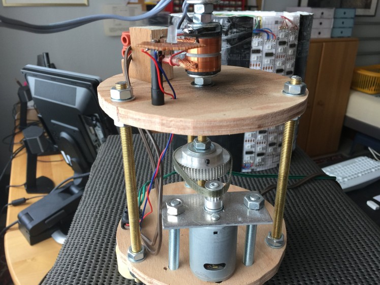 POV Cylinder Chassis (rotor removed)
The electronics is located in the upper part of the rotor. It includes the following parts:
- Arduino Due board
- Self-made shield for the Arduino Due board
- Power Supply (PS) Board
- HC-06 Bluetooth Module
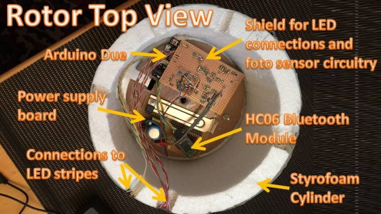 Rotor Top View
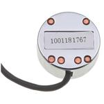
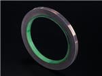
The power supply (7.5V) is fed to the power supply board via sliding contacts and a contact ring.
Four LEDs strips with in total 40 RBG LEDs are used. They are connected with cables to the Arduino Shield.
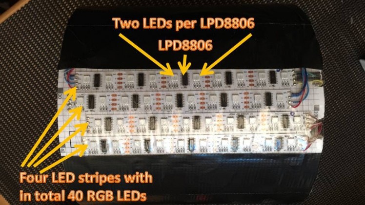 LED Stripes
The four LED stripes are placed as shown in the drawing below. By using four shifted LED stripes the distance in the Y-axis between the LEDs is divided by 4. The distance in the X-axis is handled by SW. The SW updates all 40 LEDs 151 times per revolution. The grid in the drawing corresponds to the visible pixels.
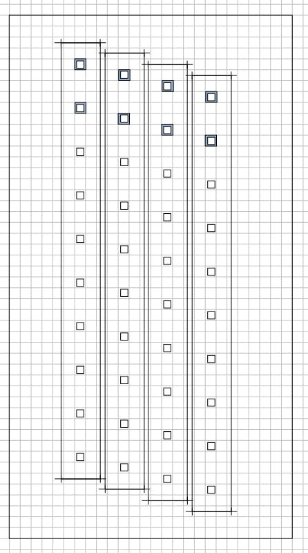 Placement of LED stripes
Electronic Circuitry
The electronic circuitry is shown in the attached PDF schematic.
There is a power supply board with a LM317 voltage regulator. The input voltage is 7.5 Volt and the output voltage is 4.6 Volt. The voltage regulator supplies the Arduino Due board and the LED strips.
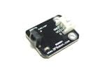
There is also a self-made shield for the Arduino. It contains the connector cables to the LED strips and a circuitry for the IR receiver. The IR receiver is used to detect the rotor position. It is connected to a timer/interrupt input of the Arduino.
There are four LED strips named STRIP0 to STRIP3. Each strip has 5 LPD8806 LED drivers and 10 RBG LEDs. STRIP0 is connect to USART0 and STRIP1 is connected to USART1. Both USARTs are operating in SPI mode. STRIP2 and STRIP3 are connected in series and are driven by the Arduino's SPI interface.
For communication with a PC a HC-06 Bluetooth module is connected to USART3. The Bluetooth module is supplied by the 3.3 Volt provided by the Arduino board.
Arduino Software
The Arduino software consists of the main program (mpc.ino) and the following libraries:
- bt - Driver SW for Bluetooth module
- LDP8806 - Driver SW for LED strips
- MemoryFree - Functions to detect available free RAM memory
- mpcgif - Playback of GIF files located in RAM or Flash memory
- pictures - Internal GIF pictures stored in Flash
- trace - Functions for SW debugging
Periodic output of the pictures to the LED strips is done interrupt driven. There are two toggle frame buffers. Each frame buffer holds one picture with 40 x 151 pixels. Each pixel is a one byte color palette index. While one frame buffer is output to the LED strips via interrupt and DMA, the other frame buffer is prepared by the main program (e.g. by the function decoding the GIF pictures). Toggling of the frame buffers is done by the frame interrupt routine.
There is one frame interrupt per revolution triggered by the IR sensor. The frame interrupt routine measures (via a hardware timer) the evolution speed and programs periodic column interrupts (one per column, i.e. 150 interrupts per revolution) with a hardware timer. The column interrupt routine outputs the current column to the LED strips. For performance reasons output is done via three DMA channels that operate fully in parallel.
The full Arduino source code is available at github.
PC Control Program
The PC Control Program (pccp) is a command line tool written in C++. It is running under Cygwin and communicates with the Arduino via Bluetooth. The pccp allows to control the POV Cylinder with the following single character commands:
- 0-7 - fill screen with color (black, red, yellow, green, cyan, blue, violet, white)
- t - draw triangle curve (as a test picture)
- s - enable or disable rotation of displayed picture
- r - draw single row
- c - draw single column
- y - playback internal GIF picture stored in Flash memory
- f - download external GIF file from PC via BT
- x - playback downloaded external GIF file
The pccp also provides an interface to a graphical user interface. Furthermore it displays the current rotation speed (in Hz and µs) and a frame counter value.
The full source code is available at github.
Graphical User Interface
The graphical user interface is an Universal Windows App. It allows to select the GIF file to be displayed by the POV Cylinder. The app has been derived from the FilePicker app from the "Microsoft Windows Universal Samples" [5].
The full source code is available at github.
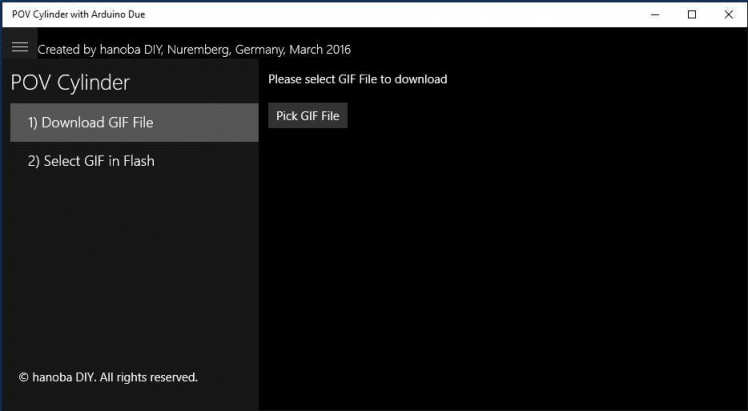 Screenshot Graphical User Interface
References
[1] https://en.wikipedia.org/wiki/Persistence_of_vision
[2] RGB LED GLOBE - POV - 40 x 200
Schematics, diagrams and documents
Code
Credits
Related products


Leave your feedback...