
Piglass

Made by 314Reactor / Wearables
About the project
A device that can measure environmental conditions and relay to the user; in glasses form.
Project info
Difficulty: Moderate
Platforms: Adafruit, Raspberry Pi, Pimoroni
Estimated time: 1 hour
License: GNU Lesser General Public License version 3 or later (LGPL3+)
Items used in this project
Hardware components


View all

Story
We are the Borg.
; ; 1 / 2
1 / 2
Key Goals Summary:
- Make a device that can measure environmental conditions and relay to the user.
- Make it wearable.
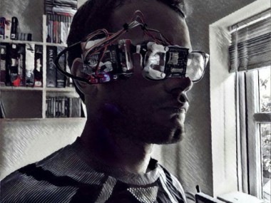
In the interests of producing more wearable tech, I thought; what would be cooler than a Raspberry Pi attached to a pair of glasses that can show sensor data to the wearers eye?
 Nothing.
I will of course require this fancy lot:
Components of Borg
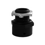
- Various screws and wires from ModMyPi
The Borg Protocols
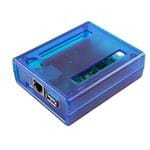
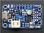
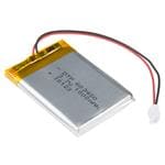
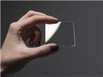
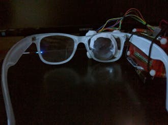
So I wanted something wearable – simple enough, I thought; get the usual Powerboost 500, battery, Pi combo all together with some sensors and whack in an OLED screen – after using Google Cardboard I realised I could use the lenses from said to make the screen readable close to the eye.
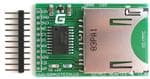
I had a scout around for some sensor kits, some were too big such as this, it would have worked but would have been a bit too bulky and I didn’t need the lighting – after some further searching I discovered the Enviro pHAT.
It covers anything a growing nerd could need to monitor, over 4 different sensors: Temp/Pressure/Light/Motion – hit the link above to see more.
Down to work
I hooked the board up to my Black HAT Hack3r and checked out this handy tutorial to get reading some >Pimoroni.
Once it was reading out some >extended header.
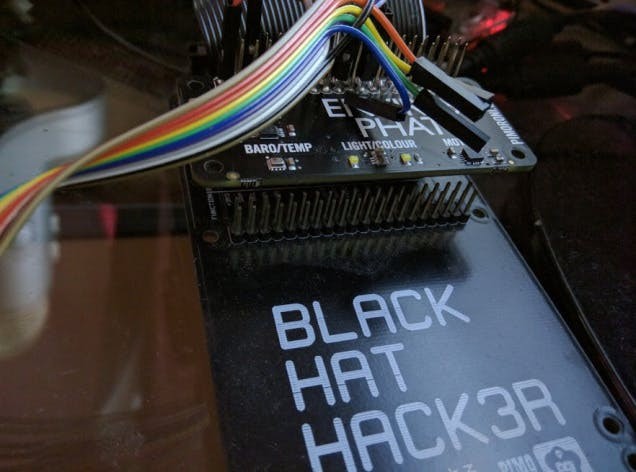 So many sensors…
As usual the simple thought turns into a few hours of trying to figure out how everything is even wired. Thanks to this random person for figuring out the correct wiring for a Raspberry Pi, if you ever see this.
Here's the OLED wiring from the above:
oled (GND/G) --- Pi ( Pin 6 Gnd) oled (Vin/+) --- Pi (Pin 1 3.3v) oled (MOSI/SI) --- Pi (Pin 19) GPIO 10 (MOSI) oled (SCK/CL) --- Pi (Pin 23) GPIO 11 (SCLK)) oled (DC/DC) --- Pi (Pin 16) GPIO 23 oled (Reset/R) --- Pi (Pin 18) GPIO 24 oled (OLEDCS/OC) --- Pin 24 (GPIO 8 CE0)You can get a good look at the Pin layout of a Pi here.
The pins on the OLED should be shown on the PCB of the board itself.
Once wired up it was OLED code time.
First I hit up a tutorial here. < This one is the most important as it guides you through the installation of the necessary software.
Then looked at some code from here. And also this handy stuff here.
I’d suggest the tutorial first followed by looking at the second links examples, these will get you setup writing stuff to the screen successfully. The third link has some further cool stuff for drawing shapes to the screen.
On my first attempts with the above I had some issues getting the screen to work, when trying to run text examples I ended up with a garbled screen – a bad feeling when you think you’ve busted a new piece of hardware in the first five minutes.
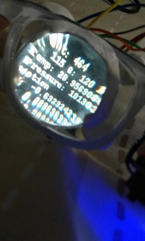
However I eventually discovered how to display a picture of a cat. With further trial and error I was able to display text – I combined this with the code for reading the Enviro pHat data and BEHOLD:
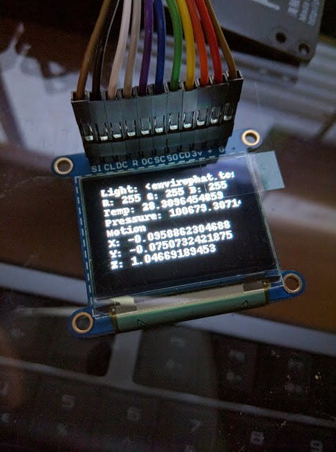 This is pretty sweet, right?
At this point I was excited – I moved onto making the text tidier and added some spacers to get the correct distance from the glasses + the lens:
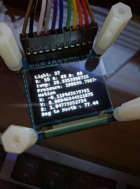 The light level at the time was 37. Valuable knowledge.
After some tweaks and testing, the final code:
#imports for the envirophat
from envirophat import light
from envirophat import leds
from envirophat import weather
from envirophat import motion
#general imports
import os
import math
import time
import decimal
#OLED screen imports
import Adafruit_GPIO.SPI as SPI
import Adafruit_SSD1351
#stuff for drawing
import Image
import ImageFont
import ImageDraw
#the setup section for the screen
RST = 24
DC = 23
SPI_PORT = 0
SPI_DEVICE = 0
disp = Adafruit_SSD1351.SSD1351_128_96(rst=RST, dc=DC, spi=SPI.SpiDev(SPI_PORT, SPI_DEVICE, max_speed_hz=8000000))
disp.begin()
width = disp.width
height = disp.height
#determining the direction of north for the heading sensor
north = 294
#main loop
while True:
	#setting up the image for the display as well as clearing anything currently on screen
	disp.clear()
	image = Image.new('1', (width, height))
	font = ImageFont.load_default()
	draw = ImageDraw.Draw(image)
	disp.clear()
	#here the sensors data is assigned to variables
	light_level = light.light()
	r, g, b = light.rgb()
	temp = weather.temperature()
	pressure = weather.pressure()
	x, y, z = motion.accelerometer()

	#calculating degrees to north
	corr_heading = (motion.heading() - north) % 360

	#if the light sensor is covered it will wait 5 seconds, if its still covered after this point, it will shutdown the raspberry pi
	if light_level == 0:
		time.sleep(5)
		light_level = light.light()
		if light_level == 0:
			os.system("sudo shutdown -h now")
		else:
			pass
	#here i assign headers to the data from the hat, into labelled strings
	text_light = ('Light: ' + str(light_level))
	text_rgb = ('R: ' + str(r) + ' G: ' + str(g) + ' B: ' + str(b))
	text_temp = ('Temp: ' + str(temp))
	text_pressure = ('Pressure: ' + str(pressure))
	text_motion_1 = ('Motion')
	text_motion_2 = ('X: ' + str(x))
	text_motion_3 = ('Y: ' + str(y))
	text_motion_4 = ('Z: ' + str(z))

	text_heading = ('Deg to North : ' + str(corr_heading))

	#finally the strings are written to the display
	draw.text((0, 0), text_light, font=font, fill=255)
	draw.text((0, 10), text_rgb, font=font, fill=255)
	draw.text((0, 20), text_temp, font=font, fill=255)
	draw.text((0, 30), text_pressure, font=font, fill=255)
	draw.text((0, 40), text_motion_1, font=font, fill=255)
	draw.text((0, 50), text_motion_2, font=font, fill=255)
	draw.text((0, 60), text_motion_3, font=font, fill=255)
	draw.text((0, 70), text_motion_4, font=font, fill=255)

	draw.text((0, 80), text_heading, font=font, fill=255)

	disp.roughimage(image)
	time.sleep(1)
As you can see the sensor data being read and displayed covers:
- Light amount 0-255
- RGB Light colour 0-255 per channel
- Temperature and Pressure
- Motion X, Y, Z
- Heading to north – calculated to show the degrees to north
To switch off you simply hold a finger over the light sensor for 5 seconds and it will execute a shutdown command on the Pi – the light levels pretty much never hit zero unless the sensor is entirely covered and I thought this would be more efficient than adding in a shutdown button. (This actually turned out to not work so well as it takes a lot for the light level to drop that far, I will probably solder on an 'off' button some time.
Call the code something like 'piglass.py' and drop a line in /etc/rc.local:
sudo python /home/pi/piglass.py &
The '&' symbol after will ensure that the script runs silently on boot, so the next time you boot and go into the command line of the Pi you won't see the script running making it a pain to type commands; shouldn't affect remoting in over SSH however.
First Contact
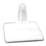
Basically you want to get the lens on so that it can view the small screen and Sugru around the top.
Then Sugru on the screen in the location it can be seen properly from the lens - Sugru on the ends of the Nylon Standoffs and sticking that to the glasses frame.
I opted to put the Pi on the right side of the glasses, GPIO facing out, and facing down - this gave me the best way to make sure the wires reached properly.
Once placed Sugru on the outer edge of the glasses frame and stick the Pi on, couple of tie wraps as well.
I also used Blu Tak to hold the wires in place - just to keep them stable and also not too permanent that I can't un-wire it in future for whatever reason.
 IMG_20160831_194032
.
 IMG_20160831_194057
 1472664965352
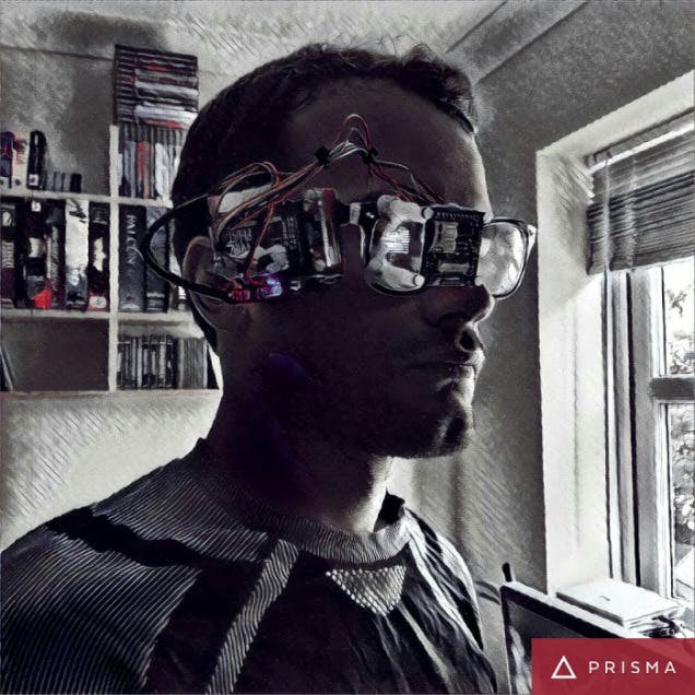
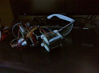
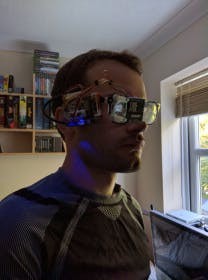
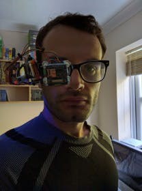
24 hours of Sugru drying later it was of course time to try them on:
 IMG_20160831_183834
 IMG_20160831_183903
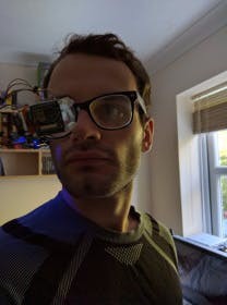 IMG_20160831_183912 (1)
As you can see the weight of the hardware drags them to one side. So I will probably attach a counterweight to the left side at some point.
Further thoughts
Having looked over my code while putting this on Hackster I've realised the code could be tidier, using a class in there and also that I did not account for the fact that the board will be on its side during use; which affects the compass - I may well revisit the code some time.
This is a great proof of concept – and with the memory card imaged I can make more similar devices quickly, possibly using different sensors or information to be relayed to the user.
I could possibly use an IR camera and an IR LED and have night vision relayed to the OLED screen for a future project.
 Sweet.
Code
Credits
Related products


Leave your feedback...