
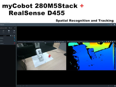
Operate Mycobot With The Spatial Recognition Of D455
Made by Elephant Robotics / Robotics
About the project
A project about a robotic arm and a depth camera working together.
Project info
Difficulty: Moderate
Platforms: Intel, ROS, M5Stack, Elephant Robotics
Estimated time: 1 hour
License: GNU General Public License, version 3 or later (GPL3+)
Items used in this project
Hardware components

Software apps and online services
Story
This article is republished from Tatsushi Matsubayashi [1] of ALBERT Inc.[2]
Link: https://blog.albert2005.co.jp/2022/12/21/realsense-d455_mycobot/
(We're honored to be allowed to translate in English and post.)
1. IntroductionThe Advanced Technology Department is working on multimodal reinforcement learning, including camera images and haptic sensors. Among other things, to implement the so-called Sim2Real, where the results of reinforcement learning in the simulator are also run on the actual machine, the robotic arm and camera of the real machine must be operated collaboratively. Therefore, in this case, we have used ROS to test the linked 6-axis robotic arm myCobot (made by Elephant Robotics) and the depth camera RealSense D455 (made by Intel), and the process and results are described in detail below.
Operating environment:
PC:Ubuntu 20.04, ROS Noetic, Python 3.8.10
Robotic Arm: myCobot280 M5Stack
Depth Camera:realsense D455
This blog describes how to create and run a simple program, but I assume that the ROS and Python environments are already set up.
2. myCobot BasicsFirst of all, prepare myCobot, but I'm a bit confused because some parts have changed in use due to firmware updates, etc. This work was done around September 2021, when myStudio version was 3.1.3. I don't think there will be any major changes, but if you see something different, please refer to the official instructions.
The following three preparations are required to run myCobot.
● Update the firmware(Basic ,ATOM)
● Robotic arm joint calibration
● Serial communication between the robotic arm and PC
Update the firmwareThe myCobot 280 M5 has an M5Stack Basic at the base and an ATOM (Basic, ATOM) at the end of the robotic arm to write the firmware to these two modules.
First, connect to the PC using USB and use chmod to allow reading and writing to the device. Also, for USB serial communication on Windows or Mac, a special driver needs to be installed.
$ sudo chmod 666 /dev/ttyUSB*Next, download the updated firmware app-myStudio (at the time of writing the latest version is 3.1.4, but only for Windows, 3.1.3 is available for Linux).
After extracting the source code and executing AppImage, it will start for Basic and ATOM, respectively. This is shown in Figure 1 and Figure 2.
Figure 1: Connect to Basic and start myStudio

Figure 1: Connect to Basic and start myStudio
Figure 2: Connect to ATOM and start myStudio

Figure 2: Connect to ATOM and start myStudio
In myStudio 3.1.3, the screen as shown in Figure 3 and Figure 4 will appear, then download the latest versions of minirobot for Basic and AtomMain for ATOM, select Flash, and write the firmware. When the writing with Basic is finished, the output of minirobot will be displayed on the panel. (Please note that if you do not write the latest version using Basic and ATOM, the robot arm may not work properly).
Figure 3: Interface for Basic firmware update

Figure 3: Interface for Basic firmware update
Figure 4: Interface for ATOM firmware update

Figure 4: Interface for ATOM firmware update
After updating the firmware, the next step is to calibrate the joint angle.
Calibration of joint anglesFirst, select Calibration in the Basic panel and press OK.
Each joint of myCobot has a notch representing the origin, as shown in Figure 5, so the notches are manually aligned with each other.
Figure 5: myCobot origin notches at each joint

Figure 5: myCobot origin notches at each joint
In this state, select Calibrate Servo in the Basic panel and press NEXT to complete the calibration. Running a test servo will allow the motor to rotate slightly around the notch to confirm proper calibration.
Serial communication between robotic arm and PCFinally, when you start the Transponder, you are able to operate myCobot from your PC via serial communication. this is easy to do, just select the transponder in the Basic panel and press OK. Then the display will show as in Figure 6, press the button for Basic.
Figure 6: Transponder's interface

Figure 6: Transponder's interface
In the other menus of the Basic panel, MainControl controls ATOM in Basic, and Information checks whether each joint is connected correctly. When myCobot does not work well on the PC, you can check if there is a problem with myCobot itself.
3. Python APIAfter the preparations are completed, we can operate myCobot on the PC. This time, I tried the method of operating from a python script using pymycobot and the method of operating MoveIt from ROS using the mycobot_moveit library.
First, install pymycobot.
$ pip install pymycobot --upgradeYou can also download the installation source from Github.
Example scripts are included in the test directory when downloaded from source. However, it won't work as-is, so be careful. I made the following example instead of rewriting.
# mycobot_control_test.py
#!/usr/bin/env python
import time

from pymycobot.mycobot import MyCobot
from pymycobot.genre import Angle, Coord

if __name__ == "__main__":
port = "/dev/ttyUSB0"
mycobot = MyCobot(port, baudrate="115200", timeout=0.1, debug=False)
 #After the baud rate are the default values

#Get the operation of the joint angle
print("get angles")
print(" degrees: {}n".format(mycobot.get_angles()))
time.sleep(0.5)

print("get radians")
print(" radians: {}n".format(mycobot.get_radians()))
time.sleep(0.5)

print("send angles: [0, 0, 0, 0, -90, 0]")
mycobot.send_angles([0, 0, 0, 0, 0, 0], 80)
time.sleep(1.5)
mycobot.send_angles([0, 0, 0, 0, -90, 0], 80)
print(" Is moving: {}n".format(mycobot.is_moving()))
time.sleep(1.5)

print("send radians: [0, 0, 0, 0, 1.57, 0]n")
mycobot.send_radians([0, 0, 0, 0, 1.57, 0], 80)
time.sleep(1.5)

print("send angle to joint 4: -90n")
mycobot.send_angle(Angle.J4.value, -90, 80)
time.sleep(1.5)

# Operations to get coordinates
print("get coordination")
print(" coordination {}n".format(mycobot.get_coords()))
time.sleep(0.5)

print("send coordination: [50, 50, 300, 0, 0, 0] → [50, 50, 300, 90, 90, 0]n")
coord_list = [50, 50, 300, 0, 0, 0]
mycobot.send_coords(coord_lis, 70, 0)
time.sleep(3.0)
coord_list = [50, 50, 300, 90, 90, 0]
mycobot.send_coords(coord_lis ,70, 0)
time.sleep(1.5)

# Scenarios using grippers
# print("open gripper")
# mycobot.set_gripper_state(0,0)
# time.sleep(1.0)
# print("close gripper")
# mycobot.set_gripper_state(1,80)
# time.sleep(1.0)

time.sleep(1.5)
print("release all servos")
mycobot.release_all_servos()
Run the mycobot_control_test.py file
$ python3 mycobot_control_test.pyCreate an instance of the MyCobot class in the mycobot module and use getters and setters to check and change the state.
Create Instance
mycobot = MyCobot(port, baudrate="115200", timeout=0.1, debug=False)Set four parameters. Enter the default value after Baud Rate. Port is the USB serial communication port. You can see the list of devices connected to your PC by running ls / dev / in Terminal. In Linux, it will be / dev / ttyUSB0 if there is no other USB port for serial communication. I think it is different for Mac and Windows, so check accordingly.
About getterget_angles ( ) and get_radians ( ) are functions that get the joint angles in degrees and radians. The return value is a list of six joint angle values.
There is also aget_coords ( ) function that gets the coordinates of the tip of the arm in a coordinate system* with the base bottom center as the origin. The return value is a 6-dimensional list with the x, y, z coordinates of the tip (mm) and the directions rx, ry, rz (angles). It is nice to have implemented inverse kinematics without MoveIt.
*coordinate system:With the Basic panel as the back, each positive direction is x: forward, y: left, and z: up. Note that the vectors are slightly different in MoveIt, which will be described later.
About setterThe functions that send the joint angles in degrees and radians aresend_angles ( )and send_radians ( ), and have two types of parameter settings.
First, when specifying and sending all 6 joints, the first parameter is the same as getter, putting 6 float values in the list type, and the speed of the joint movement * (int: 0 ~ 100) enters in the second parameter.
mycobot .send_angles ( [ 0 , 0 , 0 , 0 , 0 , 0 ] , 80 )Next, you take the angle of the joint and send it. Please put the code for the joint angle in the first parameter, the angle value in the second parameter, and the speed in the third parameter.
mycobot .send_angle ( Angle.J4.value , -90,80 )It is also possible to operate by coordinates like getter. In this case, a list of 6 elements [x, y, z, rx, ry, rz] is placed, with coordination in the first argument, velocity in the second, and mode in the third. Mode has two types, 0:angular and 1:linear
mycobot .send_coords ( [ [ 80 , 50 , 300 , 0 , 90 , 0 ] , 70 , 0 )Since the units of speed are not detailed in the source code, I think you measure it when necessary.
Other APIOnce the robotic arm moves, the motor will continue to apply torque to try to maintain the current state, so if it stays as it is, the motor will be overloaded. Therefore, let's release the motor torque with the function release_all_servos ( y) after the operation is finished.
If the robot arm is running and you instruct it to perform another action, an error will occur and it will move on to the next action. In the example script, the python built-in functiontime.sleep() is used in between to wait for each action to complete, but you can use the function is_moving() to get whether the motor is running so you can loop while, etc. (I think this function is bug and returns a constantly moving state.)
There are some other APIs that can be used to switch the power on and off, change the color of the LEDs, and check the motor status, but I omitted them this time because the goal is to move the arm.
4. ROSNext, use MoveIt in ROS to manipulate myCobot.
The elephant robot implements mycobot's moveIt and can be installed
There is a volunteer implementation of MoveIt and I decided to use it. The installation is written according to the GitHub README above.
$ cd /src
$ git clone https://github.com/Tiryoh/mycobot_ros
$ git clone https://github.com/nisshan-x/mycobot_moveit
$ rosdep update
$ rosdep install -i –from-paths mycobot_moveit
$ cd .
$ catkin_make
 #Set up work area
$ source devel/setup.bash
After completing the installation and setting up the workspace
$ roslaunch mycobot_moveit mycobot_moveit_control.launchMoveIt and Rviz GUI will start as shown in Figure 7. By dragging and dropping the green ball, the pose of the end position of the robot arm is calculated, and then by pressing the Plan and Execute button in the lower left corner, Rviz moves together with the actual robot.
Figure 7: The Rviz interface launched by mycobot_moveit_control.launch

Figure 7: The Rviz interface launched by mycobot_moveit_control.launch
* When the model and the actual machine don't work together
I don't know if this is a bug that occurs in all environments, and the model and the real machine don't always work together. This is a bug that occurs when the direction of motor rotation is reversed, so it's a bit tricky, but please compare the model with the real machine and look for the joint rotation in the opposite direction.
After confirming how many joints are rotating in the opposite direction, rewrite the URDF file describing the robot model.
/ src / mycobot_moveit / urdf / mycobot_urdf_gazebo.urdf
The description of the defined joint information is as follows.
mycobot_urdf_gazebo.urdf
~~
  <joint name="arm1_joint" type="revolute">
        <parent link="body_link" />
        <child link="arm1_link" />
        <origin xyz="0 0 0.0706" rpy="0 0 0" />
        <axis xyz="0 0 1" />
        <limit effort="30" lower="-2.88" upper="2.88" velocity="1.5" />
    </joint>
~~
Arm1 ~ arm6_joint Same instructions. The direction of the rotation axis is set to < axis xyz = "0 0 1" > < / axis >, and setting 1 → -1 reverses the rotation of the joint in the opposite direction.
In my environment, it seems that all joints except for the 3rd joint are reversed. I don't know if this is because of individual differences in the robot's servos or some other reason, please let me know if you know.
That's all there is to it, from myCobot setup to operational basics.
5. RealSence D455 BasicsI tested this time with the D455, but basically the D400 series can be used in the same way. Only the D435i and D455 have a built-in IMU sensor, but I didn't use it in this article (because the disadvantages of error accumulation are more obvious than the advantages of using the IMU in a fixed state).In addition to the D400 series with an infrared stereo camera, there is the L515 with a LiDAR, but the usage is the same. Also, I think the new one has the best performance, so I'll buy a D455. I think it's better to consult the environment you want to use before buying, because there are some parts (previous models are basically backward compatible, so there is a trade-off between price and performance).
Software installation and basic operation of the viewerInstall the library librealsense to operate RealSense. without this, realsense_ros, which will be described later, will not work. There is a document on how to install it on linux. the installation method on Windows is also in the same document library, if you need it.
# Server Public Key Registration
$ sudo apt-key adv –keyserver keyserver.ubuntu.com –recv-key F6E65AC044F831AC80A06380C8B3A55A6F3EFCDE
||  Adding a Repository
$ sudo add-apt-repository “deb https://librealsense.intel.com/Debian/apt- repo $(lsb_release -cs) main” -u
# install lib
$ sudo apt install librealsense2-dkms librealsense2- utils
# install dev
$ sudo apt install librealsense2-dev librealsense2-dbg
After the installation is complete, run realsense - viewer in the terminal to view it. If it does not work, try unplugging and plugging in the RealSense USB connection and restarting the PC. if the startup is successful, the viewer will be displayed as shown in Figure 8.
Figure 8: realsense-viewer

Figure 8: realsense-viewer
You can toggle the viewer between 2D and 3D using the 2D | 3D button in the upper right corner. In addition, you can view depth information and RGB information by opening the stereo module and RGB camera on the left.In 2D, you can see RGB and depth information in 2D. In 3D, the point cloud estimated by the depth estimating IR stereo camera is colored with a depth color map and RGB camera information and can be viewed from all angles.In addition, the D435i and D455 with built-in IMU sensors can also acquire attitude information via Motion Module. Next, let's take a look at the point cloud of Rviz using the ROS package realsense_ros. This can be installed using apt.
$ sudo apt install ros-$ROS_DISTRO-realsense2-cameraRealSense cameras are launched on the first terminal, providing color point clouds in addition to per-camera information, and Rviz is launched on the second terminal for visualization.
$ roslaunch realsense2_camera rs_camera.launch filter:=pointcloud
$rviz
In order to see the point cloud as shown in Figure 9, we will use the GUI to adjust the settings.
First, since the Fixed Frame of Global Option in the leftDisplay panel is the map, click it and change it to camera_link.
Then press the Add button at the bottom of the display panel and a new window will pop up listing the types of ROS messages that can be displayed in Rviz. Select PointCloud2 in the middle of the rviz group and press OK to add PointCloud2 to the display panel.
Also, if you click on the blank to the right of the Topic column in the group and select /camera/depth/color/pointsthat appears, the point cloud will be displayed on Rviz. By default, the point cloud size is set to 0.01 m, which is a large value, so the point clouds are displayed overlapping each other, but if you set it to around 0.001 m, you can see that the point clouds are acquired quite finely.
In addition, if you select TF from Add and add it, the camera position and orientation (axial) can be displayed. By default, the RGB camera origin and the stereo camera origin are displayed in the world and optical coordinate systems, respectively. (camera_link seems to be the same as the stereo camera origin)
Figure 9: Point cloud visualization using realsense_ros

Figure 9: Point cloud visualization using realsense_ros
Save the settings, as it is difficult to do this button pop-up every time.
Create the directory config in the workspace to save the settings, select Save Config As in Rviz's file, name the created config directory and save it.
$ rviz -d .rvizIf you change something, you can update the same file each time via Save Config. If you are just looking at point clouds and camera positions, you can easily do that withrealsense_viewer,but you can use ROS to process the raw data. Starting here is like an exercise in understanding the meaning of ROS message data.
(But, personally, this is a big stumbling block)
After executing rs_camera.launch filters:=pointcloud.
Let's look at the raw data of the /camera/depth/color/points topic sent from another terminal.
$ rostopic echo /camera/depth/color/pointsOf course this array of values is point cloud data, which is expected to be represented by RGB values in xyz coordinates and position, but it is difficult to read this directly. If you look at the numbers, you will see that each value is in the range of 0 to 255 and similar values appear periodically in a regular pattern. However, it is not reasonable to guess where x represents and where red represents from here.
So, first, find out the type of this message.
$ rostopic type /camera/depth/color/points
sensor_msgs/PointCloud2
We now know that the message type is of type sensor_msgs/PointCloud2.
Also, if you look at it from the ROS documentation you can see it as follows.
Header header # header
uint32 height # number of rows of data
uint32 width # Number of columns of data
PointField[] fields # 1 point data structure
bool is_bigendian # whether the big end
uint32 point_step # number of bytes in a point (number of 8-bit numbers)
uint32 row_step # number of data in a row (= width * point_step)
uint8[] data # raw data (8bit row_step * height data array)
bool is_dense # if true, then no invalid data
Since it is a point cloud, what is the significance of the order of the data, unlike a 2D image? As the question implies, the height and width do not seem to make sense.
It is not clear what it means to hold variables that can be calculated from other values and are unlikely to be used, but the structure is this. If you want to see the actual value of each,
$ rostopic echo /camera/depth/color/points/<Variable Name>By doing this, you can output only one variable in the data. For example, displaying back point_stepand field gives.
$ rostopic echo /camera/depth/color/points/point_step
–
20
—
$ rostopic echo /camera/depth/color/points/fields
–
name: “x”
offset: 0
datatype: 7
count: 1
–
name: “y”
offset: 4
datatype: 7
count: 1
–
name: “z”
offset: 8
datatype: 7
count: 1
–
name: “rgb”
offset: 16
datatype: 7
count: 1
—
The output will be Since point_step = 20, you can see that the data of a point is represented by 20 bytes, and you can see from the content of the field how these 20 bytes are composed.
The meaning of each variable is
name: the name of the data being represented
offset: the corresponding byte
datatype: the type code of the data being represented
count: how many data items are included
For example, the x coordinate corresponds to data from 0 to 3 and the type code is 7 (corresponding to float32), representing a data. y and z should be treated in the same way, but RGB is also represented in the same way. When I look at the 16th through 19th values corresponding to RGB, there are hexadecimal values in GBRA order. The conversion to float32 seems to be difficult to handle, so it seems that the xyz coordinates and RGB need to be handled separately.
Now that we know how to represent the data, let's actually deal with it.
(I think there is a smarter and faster way to handle the next script, so if you have any suggestions, please)
Add a script directory to the mycobot_test package and add the python script there.
$ cd /src/mycobot_test
$ mkdir scripts
$ cd scripts
$ touch red_point_detection.py
$ touch object_position_search.py
Add the dependencies to CMakeLists.txt and package.xml.
# CMakeLists.txt
find_package(catkin REQUIRED COMPONENTS
# Add rospy and sensor_msgs modules to be able to import
    rospy sensor_msgs
)
catkin_package(
# Add build package
    sensor_msgs
)
# Add scripts to the executable directory
catkin_install_python(PROGRAMS
   DESTINATION ${CATKIN_PACKAGE_BIN_DESTINATION}/scripts
)
Python
<!-- package.xml -->
<!-- add -->
  <build>rospy</build>
  <build>sensor_msgs</build>
<!-- package.xml -->
<!-- add -->
  <build>rospy</build>
  <build>sensor_msgs</build>
The following red_point_detection.py is a script that extracts only the red color from the point cloud and creates a new message.
#!/usr/bin/env python3
import time, os, sys, signal, threading
import numpy as np
import rospy
from sensor_msgs.msg import PointCloud2

class RedPointsDetectionNode(object):
    def __init__(self):
        super(RedPointsDetectionNode, self).__init__()
        self.data = PointCloud2()
        self.point_step = 20
        self.R_COL = 18
        self.G_COL = 17
        self.B_COL = 16
        rospy.init_node("red_points_detection_node")
        rospy.loginfo("red points detection start")

    # Subscriber
    def sub_pointcloud(self):
        def callback(data):
            self.sub_data = data
        sub = rospy.Subscriber("camera/depth/color/points", PointCloud2, callback = callback)
        rospy.spin()

    # Publisher
    def pub_red_pointcloud(self):
        pub = rospy.Publisher("red_point_cloud", PointCloud2, queue_size = 1)
        while not rospy.is_shutdown():
            pub_data = self.red_point_detection(self.sub_data)
            pub.publish(pub_data)

    def red_point_detection(sub_data):
            red_point_data = sub_data
            red_pointcloud = np.array([d for d in sub_data.data]).reshape(-1, self.point_step)
            r_flags = red_pointcloud < 180
            g_flags = red_pointcloud > 150
            b_flags = red_pointcloud > 150
            R_under_threshold_row = np.where(r_flags)[0][np.where(np.where(r_flags)[1]==self.R_COL)]
            G_over_threshold_row = np.where(g_flags)[0][np.where(np.where(g_flags)[1]==self.G_COL)]
            B_over_threshold_row = np.where(b_flags)[0][np.where(np.where(b_flags)[1]==self.B_COL)]
            not_red_row = np.unique(np.concatenate([R_under_threshold_row, G_over_threshold_row, B_over_threshold_row]))

            red_pointcloud = np.delete(red_pointcloud, not_red_row, axis=0).ravel().tolist()
            red_point_data.width = int(len(red_pointcloud) / self.point_step)
            red_point_data.height = 1
            red_point_data.row_step = pub_pc2_data.width * self.point_step
            red_point_data.data = red_pointcloud
            rospy.loginfo("red pointcloud {}".format(int(len(red_pointcloud) / self.point_step)))
            return red_point_data

    # node start to subscribe and publish
    def start_node(self):
        sub_pointcloud = threading.Thread(target = self.sub_pointcloud)
        pub_red_pointcloud = threading.Thread(target = self.pub_red_pointcloud)

        sub_pointcloud.setDaemon(True)
        sub_pointcloud.start()
        pub_red_pointcloud.setDaemon(True)
        pub_red_pointcloud.start()

        sub_pointcloud.join()
        pub_red_pointcloud.join()

if __name__ == "__main__":
    color_points_detector = ColorPointsDetectionNode()
    color_points_detector.start_node()
    pass
The subscriber reads the camera/depth/color/points data and the publisher extracts only the red points from the data and distributes them. The red points are processed to remove the points with RGB values of R < 180, G > 150, and B > 150 from the original point cloud. It would have been better to use HSV than RGB, which is susceptible to lighting conditions, but this time it was difficult to convert to HSV when processing PointCloud2 data, so it was shelved.(If it's C++, using PCL seems to be easy with python conversion, but it's useless with python because it's hard to write other procedures).
Once written, move it to the workspace, catkin_make and execute it.
$ roslaunch realsense2_camera rs_camera.launch filters:=pointcloud
$ rosrun mycobot_test red_point_detection.py
$ rviz -d .rviz
If you select /red_point_cloud added to the PointCloud2 message in Rviz, you can see the extracted point cloud as shown in Figure 10.
Figure 10:extracting red point cloud results

Figure 10:extracting red point cloud results
object_position_search.py is a script to find the average value of the coordinates of the extracted red points.
# object_position_search.py
#!/usr/bin/env python3
import time, os, sys, signal, threading

import numpy as np

import rospy
from sensor_msgs.msg import PointCloud2
import sensor_msgs.point_cloud2 as pc2
from geometry_msgs.msg import Point

class ObjectPositionSearchNode(object):
    def __init__(self):
        super(ObjectPositionSearchNode, self).__init__()
        rospy.init_node("object_position_search_node")
        rospy.loginfo("object position search start")
        self.object_position = Point()

    # Subscriber
    def sub_pointcloud(self):
        def callback(data):
            rospy.loginfo("subscribed pointcloud")
            xyz_generator = pc2.read_points(data, field_names = ("x", "y", "z"), skip_nans=True)
            xyz_list = [gen for gen in xyz_generator]
            list_num = len(xyz_list)
            x = np.array([xyz_list[i][0] for i in range(list_num) if (xyz_list[i][2] < 1.0 and xyz_list[i][2] > -1.0)])
            y = np.array([xyz_list[i][1] for i in range(list_num) if (xyz_list[i][2] < 1.0 and xyz_list[i][2] > -1.0)])
            z = np.array([xyz_list[i][2] for i in range(list_num) if (xyz_list[i][2] < 1.0 and xyz_list[i][2] > -1.0)])

            self.object_position.x = np.average(x)
            self.object_position.y = np.average(y)
            self.object_position.z = np.average(z)

        sub = rospy.Subscriber("red_point_cloud", PointCloud2, callback = callback)
        rospy.spin()

    # Publisher
    def pub_target_position(self):
        pub = rospy.Publisher("object_position", Point, queue_size=1)
        while not rospy.is_shutdown():
            rospy.loginfo("published object position: {:.5f}, {:.5f}, {:.5f}n".format(self.object_position.x, self.object_position.y, self.object_position.z))
            pub.publish(self.object_position)
    def start_node(self):
        sub_pointcloud = threading.Thread(target = self.sub_pointcloud)
        pub_target_position = threading.Thread(target = self.pub_target_position)

        sub_pointcloud.setDaemon(True)
        sub_pointcloud.start()
        pub_target_position.setDaemon(True)
        pub_target_position.start()

        sub_pointcloud.join()
        pub_target_position.join()

if __name__ == "__main__":
    object_position_searcher = ObjectPositionSearchNode()
    object_position_searcher.start_node()
    pass
With red_point_search.py running previously, start a new terminal and run it.
$ rosrun mycobot_test object_position_search.pyIt takes the average of the coordinate values of red_point_cloud and distributes them, while recording these values. Coordinates are in meters, and this script retrieves points within 1.0 meters. Since the coordinates obtained using rospy.loginfo are logged, the coordinates are output to the terminal.
There is a point_cloud2 module in the sensor_msgs library for processing and reading PointCloud2 data, converting coordinate values from 4Byte to float32. The content is simple, but I had a hard time understanding the existence of this module. If you have other complex message data, it's best to see if there is an accompanying processing module. This is the real sense setup and data processing. Regarding data processing, I think you still need to find ways to process faster (or improve the algorithm), depending on the application.
6. Connecting myCobot to RealSense D455 using ROSNow that the RealSense data processing is done, I want to use it in combination with myCobot. Therefore, the most important thing is the transformation from the RealSense camera coordinate system to the myCobot coordinate system. there is a TF (transform) on Rviz that shows the camera axes, but you need to understand this. As the name suggests, it describes a coordinate transformation that describes the relationship between one coordinate system and another. First, let's see what happens if this TF is not set.
$ roslaunch realsense2_camera rs_camera.launch filter:=pointcloud
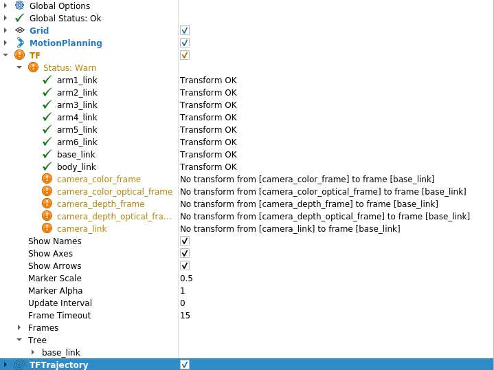
$ roslaunch mycobot_moveit mycobot_moveit_control.launchYou will then see a warning in the Rviz display panel as shown in Figure 11. The message is that there is no Transform from each coordinate system of the camera to base_link (the origin of myCobot).
So let's create a package that broadcasts TF (coordinate transformation) from the camera to myCobot. sorry for the back and forth between C++ and Python, but this time I'll use roscpp. first create a package.
$ cd <your_ros_ws_for_MyCobot>/src
$ catkin_create_pkg tf_broadcaster roscpp
$ cd tf_broadcaster
$ touch src/tf_broadcaster.cpp
Rewrite the generated tf_broadcaster.cpp, CMakeLists.txt, package.xml as follows. Note that the C++ file is a class, as it was created to practice creating nodes in a class, but it can be written more easily.
// tf_broadcaster.cpp
#include <ros/ros.h>
#include <geometry_msgs/TransformStamped.h>
#include <tf2_ros/static_transform_broadcaster.h>
#include <tf2_geometry_msgs/tf2_geometry_msgs.h>

class TfBroadcaster
{
public:
    TfBroadcaster();
    ~TfBroadcaster();
// Broadcast
    void BroadcastStaticTfFromCameraToMyCobot();

private:
    ros::NodeHandle nh_;
// TF Broadcaster
    tf2_ros::StaticTransformBroadcaster static_tf_broadcaster_;
// constant
    double PI_ = 3.1419265;
};

TfBroadcaster::TfBroadcaster(){}
TfBroadcaster::~TfBroadcaster(){}

void TfMyCobotBroadcaster::BroadcastStaticTfFromCameraToMyCobot()
{
    geometry_msgs::TransformStamped transformStamped;
    transformStamped.header.stamp = ros::Time::now();
    transformStamped.header.frame_id = "camera_color_frame"; //link
    transformStamped.child_frame_id = "base_link";
    // son link
  // Parallel movement
    transformStamped.transform.translation.x = -0.3;
    transformStamped.transform.translation.y = -0.3;
    transformStamped.transform.translation.z = -0.3;
    // Turning back
        tf2::Quaternion q;
    q.setEuler(0, 0, 0);
    transformStamped.transform.rotation.x = q.x();
    transformStamped.transform.rotation.y = q.y();
    transformStamped.transform.rotation.z = q.z();
    transformStamped.transform.rotation.w = q.w();

    static_tf_broadcaster_.sendTransform(transformStamped);
}

int main(int argc, char** argv)
{
    ros::init(argc, argv, "tf_mycobot_broadcaster");
    TfMyCobotBroadcaster tf_mycobot_broadcaster;
    tf_mycobot_broadcaster.BroadcastStaticTfFromCameraToMyCobot();

    ros::Rate loop_rate(10);
    while(ros::ok()){
        ros::spinOnce();
        loop_rate.sleep();
    }
    return 0;
}
# CMakeLists.txt
cmake_minimum_required(VERSION 3.0.2)
project(tf_broadcaster)
find_package(catkin REQUIRED COMPONENTS
  roscpp geometry_msgs tf2_geometry_msgs)
catkin_package( CATKIN_DEPENDS geometry_msgs tf2_geometry_msgs)
include_directories(${catkin_INCLUDE_DIRS})
add_executable(tf_mycobot_broadcaster src/tf_mycobot_broadcaster.cpp)
target_link_libraries(tf_mycobot_broadcaster ${catkin_LIBRARIES})
<!-- package.xml -->
<?xml version="1.0"?>
<package format="2">
  <name>tf_broadcaster</name>

  <version>0.0.0</version>
  <description>The transform broadcaster package</description>
  <maintainer email="root@todo.todo">root</maintainer>
  <license>TODO</license>

  <buildtool_depend>catkin</buildtool_depend>
  <depend>tf2_geometry_msgs</depend>
  <depend>geometry_msgs</depend>
</package>
As you can see, we set the instance variable of the transformStamped class and broadcast the instance. The broadcast variable type is tf2_ros::StaticTransformBroadcaster, but this time we use a static TF because the camera and robot positions are fixed. There are also dynamic TFs that can be used when the position relationship changes over time, for those who are interested.
Here, the positional relationships are not known yet, so the values are temporary, but we can make up the display, so let's try it. Also, the parent link is camera_color_frame instead of camera_link, because the origin of the latter matches the point cloud coordinate system. After catkin_make, run rs_camera.launch and mycobot_moveit_control.launch as before, and run tf_broadcaster in another terminal.
$ rosrun tf_broadcaster tf_broadcasterThis broadcasts the position relationship between the imager and myCobot's base_link, so the TF warning disappears. If a point cloud is added in this state, it will look like in Figure 12. Of course, the position relationship between the camera and myCobot is temporary, so the position of myCobot seen by the camera and the position of the model shown in Rviz do not overlap.
Figure 12: Testing TF Broadcast

Figure 12: Testing TF Broadcast
So, next we will calibrate the relative pose and position of the robot as seen from the camera.
I think there is another way to specify the position relationship by fixing the camera at a specific location, but this time we mark three points to determine the robot coordinates and we calibrate the position relationship by finding a unit vector and calculating it in relation to the camera coordinate system.
Some of you may have noticed that the previous photos were taken with the markers already attached, but the markers were placed in the manner shown in Figure 13.
Figure 13: Placement of myCobot position and orientation calibration markers

Figure 13: Placement of myCobot position and orientation calibration markers
ration markers
The origin (bottom center) of myCobot is at the midpoint of markers 2 and 3, and marker 1 is perpendicular to line segments 2 and 3 at that origin.
1. First, rewrite red_point_detection.py and create blue_point_detection.py to get the point cloud of blue marker. The script is omitted here because it just rewrites the RGB range to be extracted. After that, I think there are multiple ways to get the coordinate transformation from there, but this time it is obtained by the following process. Determine marker coordinates Subscribe to marker point cloud
a. Clustering point clouds into three (by k-means method)
2. Determine the origin and unit vectors The midpoint of Markers 2 and 3 is the origin V_robot
a. The unit vectors V_X and V_Y of X and Y are V_robot → Marker 1, V_robot → Marker 2, respectively.
b. The unit vector of Z is the fork product of the plane with markers and the normal vector
3. Use Euler angles to create a rotation from the camera pose to the robot pose theta_1 = the elevation angle of the camera relative to the horizontal plane
a.theta_2 = angle of rotation toward the front of the camera
b.theta_3 = angle between the camera and the direction in front of the robot
4. Translate the origin in the V-Z direction to the fixed base of myCobot (2.7 cm)
* The axis from which the Eulerian rotation starts is arbitrary, so the result will vary depending on the library used.(I don't think everyone has bothered to do this, so I'm wondering if you pass the unit vector and the origin of the two coordinate systems if there is some library that converts it to TF.)
The following script is added to the scripts directory.
# mycobot_position_calibration.py
#!/usr/bin/env python3
import time, os, sys, signal, threading

import numpy as np

import rospy
from sensor_msgs.msg import PointCloud2
from geometry_msgs.msg import Point
import sensor_msgs.point_cloud2 as pc2

class MyCobotPositionCalibrationNode(object):
    def __init__(self):
        super(MyCobotPositionCalibrationNode, self).__init__()
        rospy.init_node("mycobot_position_calibration_node")
        rospy.loginfo("mycobot position calibration start")

    # Subscriber
    def sub_pointcloud(self):
        def callback(data):
            self.data = data
            rospy.loginfo("subscribed pointcloud")
            xyz_generator = pc2.read_points(self.data, field_names = ("x", "y", "z"), skip_nans=True)
            xyz_list = [xyz for xyz in xyz_generator if (abs(xyz[0]) < 0.8 and abs(xyz[1]) < 0.8 and abs(xyz[2]) < 0.8)]
            xyz_array = np.array(xyz_list)

            if len(xyz_list) > 3:
                marker_centroids = self.kmeans(3, xyz_array)
                rospy.loginfo("n marker positionsn{}".format(marker_centroids))
                translation = self.cal_translation(marker_centroids)
                rospy.loginfo("n translationn{}".format(translation))

        sub = rospy.Subscriber("blue_point_cloud", PointCloud2, callback = callback)
        rospy.spin()

    # node start
    def start_node(self):
        sub_pointcloud = threading.Thread(target = self.sub_pointcloud)
        sub_pointcloud.setDaemon(True)
        sub_pointcloud.start()
        sub_pointcloud.join()

    # clustering method
    def kmeans(self, k, X, max_iter=30): # k: cluster num, X: numpy array
        data_size, n_features = X.shape
        centroids = X[np.random.choice(data_size, k)]
        new_centroids = np.zeros((k, n_features))
        cluster = np.zeros(data_size)
        for epoch in range(max_iter):
            for i in range(data_size):
                distances = np.sum((centroids - X[i]) ** 2, axis=1)
                cluster[i] = np.argsort(distances)[0]
            for j in range(k):
                new_centroids[j] = X[cluster==j].mean(axis=0)
            if np.sum(new_centroids == centroids) == k:
                break
            centroids = new_centroids
        max_norm = 0
        min_norm = 0
        sorted_centroids = []
        for centroid in centroids:
            norm = centroid[2]
            if norm > max_norm:
                sorted_centroids.append(centroid)
                max_norm = norm
                if min_norm == 0:
                    min_norm = sorted_centroids[0][2]
            else:
                if norm > min_norm and min_norm != 0:
                    sorted_centroids.insert(1, centroid)
                else:
                    sorted_centroids.insert(0, centroid)
                    min_norm = norm
        sorted_centroids = np.array(sorted_centroids)

        return sorted_centroids

    # translation angles calculation
    ## calculation
    def cal_translation(self, marker_points):
        # マーカー1, 2, 3の位置ベクトル
        #Position vector of marker 1, 2, 3
        a_1, a_2, a_3 = marker_points
        # カメラからロボットへのベクトル
        #Vector from camera to robot
        V_robot = self.cal_robot_position_vector(a_2, a_3)
        # ロボットのXYZ単位ベクトル
        #XYZ unit vector of the robot
        V_X = (a_2 - V_robot) / (np.linalg.norm(a_2 - V_robot))
        V_Y = (a_1 - V_robot) / (np.linalg.norm(a_1 - V_robot))
        V_Z = self.cal_normal_vector(marker_points)

        # カメラの水平面に対する仰角
        # Elevation angle of the camera relative to the horizontal plane
        theta_1 = - (np.pi/2 - self.cal_subtended_angle(-V_robot, V_Z))
        # カメラの正面方向の回転角
        #Rotation angle of the camera in the frontal direction
        V_Y_camera = np.array([0, 1, 0])
        V_Y_camera_rotated = self.cal_rotate_vector_xaxis(V_Y_camera, -theta_1)
        theta_2 = - self.cal_subtended_angle(V_Z, -V_Y_camera_rotated)
        # カメラとロボットのそれぞれの正面方向とのなす角
        #Angle between the camera and the respective frontal direction of the robot
        _, V_robot_projected_to_plane = self.cal_vector_projection(V_robot, V_Z)
        theta_3 = self.cal_subtended_angle(V_Y, V_robot_projected_to_plane)
        # mycobotの位置を土台の高さ0.027 m, V_Z方向に平行移動
        # mycobot position at foundation height 0.027 m, parallel to V_Z direction
        V_robot = V_robot + 0.027*V_Z

        return V_robot, theta_1, theta_2, theta_3


    ## vector and angle caluculation
    def cal_robot_position_vector(self, a_2, a_3):
        return (a_2 + a_3) / 2

    def cal_normal_vector(self, marker_points):
        a_1 = marker_points[0]
        a_2 = marker_points[1]
        a_3 = marker_points[2]
        A_12 = a_2 - a_1
        A_13 = a_3 - a_1
        cross = np.cross(A_13, A_12)
        return cross / np.linalg.norm(cross)

    def cal_subtended_angle(self, vec_1, vec_2):
        dot = np.dot(vec_1, vec_2)
        norm_1 = np.linalg.norm(vec_1)
        norm_2 = np.linalg.norm(vec_2)
        return np.arccos( dot / (norm_1 * norm_2) )

    def cal_vector_projection(self, org_vec, normal_vec):
        # org_vec: 射影したいベクトル
        # org_vec: the vector you want to project
        # normal_vec: 射影したい平面の法線ベクトル
         # normal_vec: Normal vector of the plane to be projected
        projected_to_vertical = np.dot(org_vec, normal_vec) * normal_vec
        projected_to_horizontal = org_vec + projected_to_vertical
        return projected_to_vertical, projected_to_horizontal

    def cal_rotate_vector_xaxis(self, vec, angle):
        rotate_mat = np.array([[1, 0, 0], [0, np.cos(angle), np.sin(angle)], [0, -np.sin(angle), np.cos(angle)]])
        return vec.dot(rotate_mat)

    def cal_rotate_vector_yaxis(self, vec, angle):
        rotate_mat = np.array([[np.cos(angle), 0, -np.sin(angle)], [0, 1, 0], [np.sin(angle), 0, np.cos(angle)]])
        return vec.dot(rotate_mat)

    def cal_rotate_vector_zaxis(self, vec, angle):
        rotate_mat = np.array([[np.cos(angle), np.sin(angle), 0], [-np.sin(angle), np.cos(angle), 0], [0, 0, 1]])
        return vec.dot(rotate_mat)

if __name__ == "__main__":
    mycobot_position_calibrator = MyCobotPositionCalibrationNode()
    mycobot_position_calibrator.start_node()

    pass
This time we set the camera and robot in order from the closest marker_1, marker_2 and marker_3 according to their position relationship, but it should be noted that it needs to be adjusted according to the placement of the camera.
After the build is complete, the camera, color search, and calibration nodes are launched in each of the three terminals.
$ roslaunch realsense2_camera rs_camera.launch filter:=pointcloud
$ rosrun mycobot_test blue_point_detection.py
$ rosrun mycobot_test mycobot_position_calibration.py
This will record the transformations t_x, y, z (m) and the Euler angles theta_1, 2, 3 (radians) to the terminal of mycobot_position_calibration.py. The values fluctuate due to point cloud data collection and clustering, so the values are averaged multiple times.(In this setup, both the parallel translation and Euler angles fluctuate by about 1%)
After getting the value, rewrite the temporary value in tf_broadcaster.cpp.
// tf_broadcaster.cpp
~~
# それぞれ t_x,y,z と theta_1,_2,_3 に得られた値を入れる
# Put the obtained values in t_x,y,z and theta_1,_2,_3 respectively
    transformStamped.transform.translation.x = t_z;
    transformStamped.transform.translation.y = -t_x;
    transformStamped.transform.translation.z = -t_y;

    tf2::Quaternion q;
    q.setEuler(theta_1, theta_2, theta_3);
~~
I was looking for TF from camera_color_frame to base_link, and found that the point group coordinate system is camera_depth_optical_frame, and the xyz direction is different after calculation (I didn't notice the difference, I was confused) so x = t_z, y = - t_x, z = - t_y.
After rewriting and catkin_make, start the node.
$ roslaunch realsense2_camera rs_camera.launch filter:=pointcloud
$ roslaunch mycobot_moveit mycobot_moveit_control.launch
$ rosrun tf_broadcaster tf_broadcaster
The position relationship between the camera and the robot is then reflected, and the robot on the point cloud and the robot model shown in Rviz can be superimposed, as shown in Figure 14.
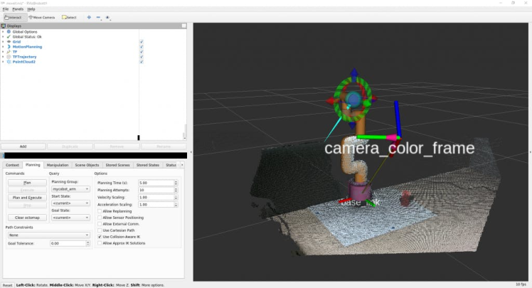
Figure 14: Setting the value obtained from the calibration to TF and broadcasting it was not perfect, but I was able to keep the deviation within an acceptable range to simply reach and pick up the object.
When moving the point cloud and the superimposed robot model, you can see that.
myCobot's joints have a little bit of play, which makes it difficult to make precise movements.
Since the point cloud coordinate system obtained from RealSense is converted to the coordinate system of myCobot, let's try to position the tip of myCobot towards the object.(I tried to reach it using MoveIt, but it was stuck in C++, so I made a script that can be easily operated with pymycobot)
Since the coordinates are in the optical coordinate system of the camera, convert them to the myCobot coordinate system with the previously obtained translations and rotations. Add the following to the script directory.
# mycobot_reaching.py
#!/usr/bin/env python3
import time, os, sys

import numpy as np
import quaternion
from pymycobot.mycobot import MyCobot

import rospy
from geometry_msgs.msg import Point
from tf.transformations import quaternion_from_euler

class MyCobotReachingNode(object):
    def __init__(self):
        super(MyCobotReachingNode, self).__init__()
        rospy.init_node("mycobot_reaching_node")
        rospy.loginfo("mycobot reaching start")

        # メンバ変数
        # mycobot インスタンス
        # member variable
        # mycobot instance
        port = "/dev/ttyUSB0"
        self.mycobot = MyCobot(port, baudrate="115200", timeout=0.1, debug=False)
        # 平行移動と回転
        # 光学座標系→mycoboto座標系なので4.2節とXYZ軸が違うことに注意
        # Translation and rotation
        # Note that the XYZ axes are different from those in section 4.2 because the optical coordinate system is a mycoboto coordinate system
        self.translation_from_camera_to_mycobot = np.array([t_x, t_y, t_z])
        q = quaternion_from_euler(-theta_2, -theta_3, theta_1)
        self.rotation_from_camera_to_mycobot = quaternion.as_quat_array(q)
        # subscriber
        self.sub_point()

    # Subscriber
    def sub_point(self):
        def callback(data):
            rospy.loginfo("subscribed target point")
            self.mycobot_move(data)

        sub = rospy.Subscriber("object_position", Point, callback = callback)
        rospy.spin()

    # move mycobot
    def mycobot_move(self, point_data):
        # mycobot座標系への変換
         # Convert to mycobot coordinate system
        target_point = np.array([point_data.x, point_data.y, point_data.z])
        target_point -= self.translation_from_camera_to_mycobot
        target_point = quaternion.rotate_vectors(self.rotation_from_camera_to_mycobot, target_point)

        # mm単位のため*1000、手前中心付近にリーチングするためx-20mm, z+40mm
        # *1000 for mm increments, x-20mm, z+40mm for reaching around the center of the front
        coord_list = [target_point[0]*1000-20, -target_point[2]*1000, target_point[1]*1000+40, 0, 90, 0]
        self.mycobot.send_coords(coord_list, 70, 0)
        time.sleep(1.5)

if __name__ == "__main__":
    reaching = MyCobotReachingNode()
    pass
This time, I'll mobilize all the libraries I've used and the scripts I've made.
You can run rs_camera.launch, mycobot_moveit_control.launch, tf_broadcaster, red_point_detection.py, object_position_search.py, mycobot_reaching.py in 6 terminals, but each time you open a terminal you have to set it up... And debugging would be difficult, so create your own startup file.
Go to your workspace, create the directories and files for startup, and add the startup path to CMakeLists.txt.
$ cd <your_ros_ws_for_MyCobot>/src/mycobot_test
$ mkdir launch
$ cd launch
$ touch mycobot_reaching.launch
<!-- mycobot_reaching.launch -->
<launch>
    <include file="$(find mycobot_moveit)/launch/mycobot_moveit_control.launch" />
    <include file="$(find realsense2_camera)/launch/rs_camera.launch">
        <arg name="filters" value="pointcloud"/>
    </include>

    <node name="tf_broadcaster" pkg="tf_broadcaster" type="tf_broadcaster" />

    <node name="color_points_detectior" pkg="mycobot_test" type="red_points_detection.py" output="screen" />
    <node name="object_position_searcher" pkg="mycobot_test" type="object_position_search.py" output="screen" />
    <node name="mycobot_reaching_node" pkg="mycobot_test" type="mycobot_reaching.py" />
</launch>
# CMakeLists.txt
~~
# Add launch file
install(FILES
  DESTINATION ${CATKIN_PACKAGE_SHARE_DESTINATION}/launch
)
~~
The structure of the startup file is simple, just arrange the nodes to be run simultaneously and the startup file in the startup tab. To execute a node, write any node name in the node tag, and write the package name and executable name as you would for rosrun. Add output="screen" if you want the output to be displayed on the command line.
Include the file path in the include tag when executing the startup in the boot file. Try catkin_make and run it.
$ roslaunch mycobot_test mycobot_reaching.launchI was able to move myCobot to track the red objects captured by RealSense, just like in Movie 1.
There was a lot of lag before following the project, and I always felt that I still didn't learn enough in all aspects.
7. SummaryIn this article, I summarize how to use ROS to coordinate the 6-axis robotic arm myCobot and the depth camera RealSense D455. I have no experience in robotics development, including ROS. I don't think there's a blog that summarizes what I've tried from scratch so far, so if you bought a robotic arm or depth camera but don't know how to use it, I hope it's helpful to those people who want to know how to use it.Also, I would appreciate it if someone with robotics development experience or who is good at data processing could point out that it would be better to do something like this.
This time I applied the reinforcement learning model I learned in the simulator to myCobot and also performed picking experiments, so I may write another blog as part 2.
Reference
1. Tatsushi Matsubayashi, 2022.12.21, RealSense D455による空間認識でmyCobotを操作. https://blog.albert2005.co.jp/2022/12/21/realsense-d455_mycobot/
2. ALBERT Inc. https://www.albert2005.co.jp/english/
Credits
Elephant Robotics
Elephant Robotics is a technology firm specializing in the design and production of robotics, development and applications of operating system and intelligent manufacturing services in industry, commerce, education, scientific research, home and etc.
Related products


Leave your feedback...