

Obiwan, An Orientable Laser Pointer

Made by remi-mazhar / 3D Printing / Lights
About the project
Obiwan is a laser pointer capable of orienting itself in any given direction, and of "light painting".
Project info
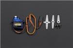
Items used in this project


Story
Introduction
Obiwan is a laser pointer capable of orienting itself in any given direction.
Context
We are a small IT club in a high school with about 8 active members. As a very young club managed entirely by students, we are very proud to showcase this project, made in a few weeks with only about 10 euros of budget in total. Hope you will enjoy reading about this project as much as we enjoyed making it!
Goals
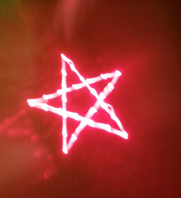
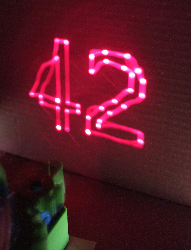
The main goal is to be able to orient the laser in an arbitrary direction. We then hope to use the device to draw a pattern and capture it with a long exposure photo, similar to light painting. Finally, if all our previous goals are achieved, we may try to fully automate the laser to draw a pattern from a vector image.
Basic principle
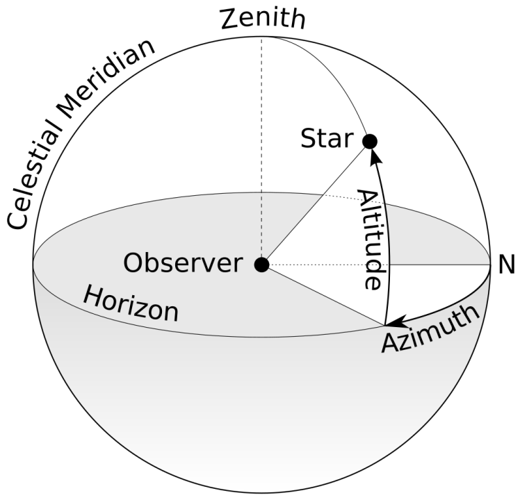
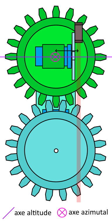
To steer the laser, we will use two motors: one will control the left-right movement, called Azimut, while the other will control the up-down movement, called Altitude. This vocabulary is borrowed from the celestial coordinate system called “horizontal coordinate system” used in astronomy:
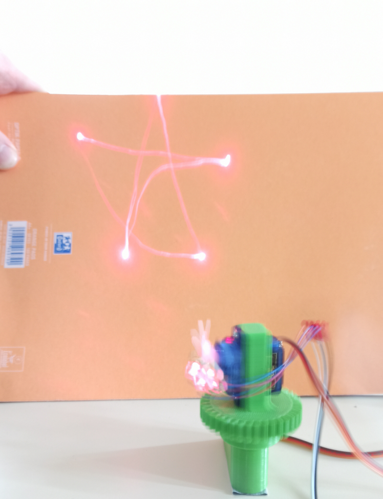
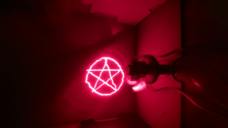
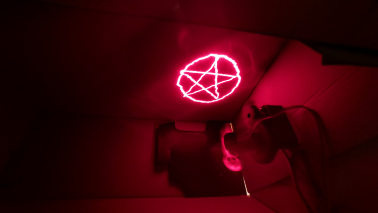
To photograph the created designs, we will use the light painting technique. It consists in taking a photo with a relatively long exposure (the duration that the camera will catch the light) to have the light point’s trajectory appear on the image.
Difficulties encountered and solutions
Architectural/manufacturing choices
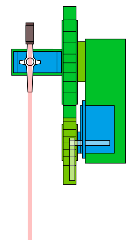
The movement is controlled by servo motors and an Arduino. The motor “Azimut” drives the gear wheel on which is placed the motor “Altitude”. The laser is taped on the motor “Altitude”. The structure is 3D-printed in PLA.
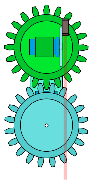
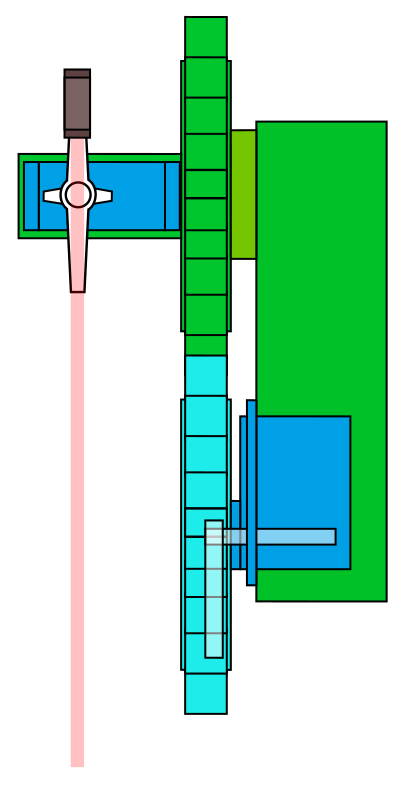
The altitude motor's center of mass is positioned in the center of its gear wheel, which makes it so the lazer has an eccentricity compared to the azimuthal axis. This means the laser beam is not secant with the azimutal’s rotational axis.
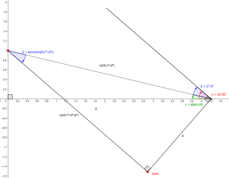
Eccentricity
This eccentricity drives the drawings to be deformed. We fixed this issue thanks to trigonometry: the program takes the target's coordinates in, and calculates the angles to give to the motors to point at, despite the eccentricity.
Precision
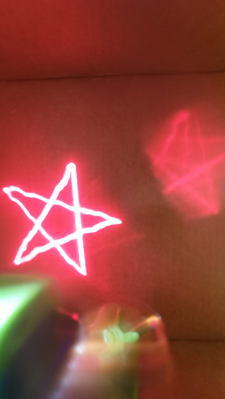
In the beginning, we drew on a wall approximately 1.5m from the laser. However, the tracing lacked precision, since our motors only have an approximately 1° precision. So we first reduced the size of the azimuth axis gear to have a 1:2 reduction, and thus have an accuracy of 0.5 degrees. This had the side effect of making the device more compact.
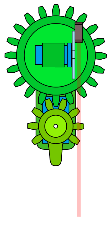
This however wasn't enough to solve the issue, because the altitude axis remained the same, and not even the 0.5° precision wasn't enough. We then realised that simply bringing the device closer to the drawing surface greatly increased accuracy, as the drawings were then more degrees wide.
Rectilinearity
With our device, when moving from one position to another the path was not straight, because the speed of the motors is not constant. To draw straight, we therefore point to intermediate positions.
By adding more intermediate points, the strokes are straighter and more uniform.
Final Results
CAD, enclosures and custom parts
Credits
Related products


Leave your feedback...