

Nxp Cup Project

Made by Polytech_nice_sophia / Automotive / Robotics / Vehicles / IoT
About the project
The NXP Cup is a world wide competition where trio student teams build and program an autonomous model car to be raced on a track. The fastest one achieving one lap within its three attempts win the most points. There is also other tracks with various specificities, being part of optional extra disciplines.
Project info
Difficulty: Difficult
Estimated time: 5 months
License: GNU General Public License, version 3 or later (GPL3+)
Items used in this project
Hardware components

View all
Software apps and online services
Story
NXP Cup
ATHIAS Benoit, LINHARES Thomas, TANTI Luca
ft. MULLER Fabrice
1. Context
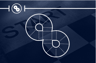
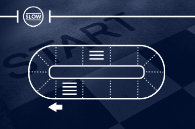
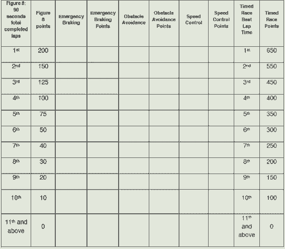
The NXP Cup is a world wide competition where trio student teams build and program an autonomous model car to be raced on a track. The fastest one achieving one lap within its three attempts win the most points. There is also other tracks with various specificities, being part of optional extra disciplines, rewarded with additional points : - The Figure 8 track, where students have sixty seconds to complete as many laps as possible within three attempts, without exiting the road. The team with the most laps completed wins.
- The Figure 8 track, where students have sixty seconds to complete as many laps as possible within three attempts, without exiting the road. The team with the most laps completed wins.
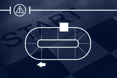
- Obstacle avoidance, which the car has to avoid an obstacle placed on the track. Nothing is allowed to touch the obstacle, and no wheel is allowed to get out of the track. Only one attempt is enabled and can last ninety seconds maximum.
- Speed limit zone, according to a 4 stripes pattern on the track, the car's speed has to be reduced about half of its initial speed. After a 3 stripes pattern representing the end of the speed zone, its speed has to be resumed. No wheel is allowed to get out of the track, only one attempt is enabled and can last ninety seconds maximum.
- Emergency braking, which the car must stop when an obstacle is place ahead. The car is not able neither to touch the obstacle nor to exit the track. Only one attempt is allowed.
The team with the most point according to the scoring system win the NXP Cup.
2. Schedule
2.1. Gantt
2.1.1. Initial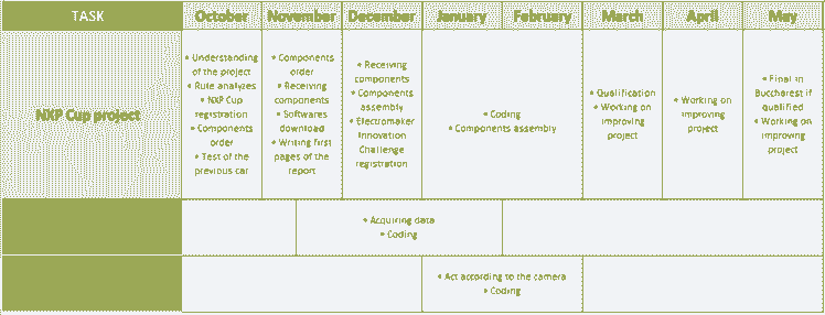
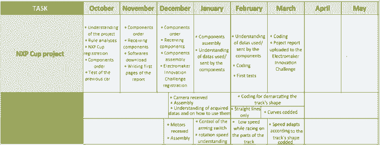
2.1.2. Realized
2.2. Work done in session
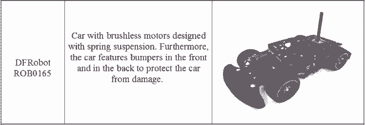
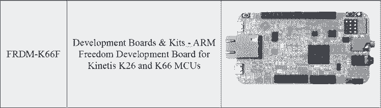
11th October : Understanding the project and rules to compete in the NXP CUP.We have thought about future orders to be made. We thought we would take the RDDRONE-FMUK66 card. Order of the car DFRobot ROB0165 Smart Robot Racing Car with Brushless Motors.
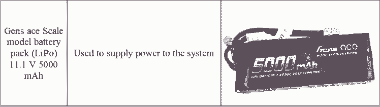
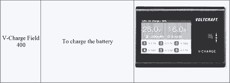
17th & 25th October : Handling and analysis of the existing project. We did tests on the car to see what to improve. We noticed that the car did not have an internal battery, so we ordered one and its charger. Moreover, it seems to have trouble to turn on the left. The wheels weren’t parallel, which makes the trajectory of the car imprecise when it picks up speed. On the other hand, to turn on the right the car negotiates the curves very well even at a high speed.
8th November : Reception of the card, configuration, and installation of the software for communicating with the card.
15th November : Download of the software to code on the board. Encountered problem : One command was missing in NXP datasheet: $ git clone https://github.com/PX4/Firmware.git We had to modify the line according to the following : $ cd ~/src/Firmware && make nxp_fmuk66-v3_default To $ cd ~/Firmware && make nxp_fmuk66-v3_default
22nd November : CMUcam5 received. Download of the software to code on the camera via the following website : https://nxp.gitbook.io/nxp-cup/developer-guide/development-tools/rddrone-fmuk66-development/setting-up-mcuxpresso We began installation and settings of MCUXpresso and the download of the SDK.
29nd November : 10.3.1 version that we installed is not the good one because the SDK generates an error. We had to take 10.3.0 version and SDK 2.5. We had an issue in the building project because the px4_sitl_default folder was not found. So we generated it that way : $ cd ~/Firmware && make px4_sitl_default
14th December : We received the cars and began to assemble them, cf 3.3 Assembly.
21st December : The first car had been assembled, the second one could not be assembled because of pieces which could not fit cf 3.4.Issues encountered.
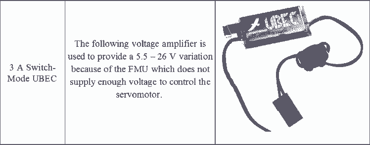
18th January : We restarted to work on the project after a little break. We began to look for the datas acquired with the camera and control the trigger of the motors. 3 A Switch-Mode UBEC received and welded. It will powered the servomotor correctly, previously the FMU did it and did no supply enough voltage for controlling.
25th January : We can now control the trigger of the motors with the arming switch. We began to work on the control of their rotation speed.
7th February : We tried to control the motors according to the datas acquired with the camera, without success...
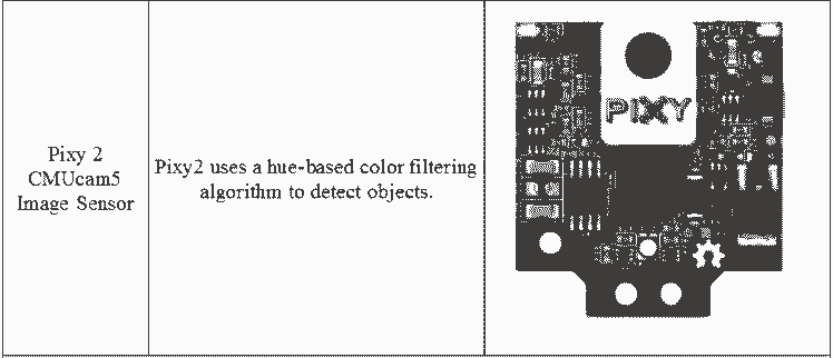
14th February : As previously, we got stuck on the advancement of the code. So we have done some tests with the Pixy 2 cam : if used without the FMU board and only with its specific software PixyMon we were able to have data from the camera and visualize images. Connecting it to our FMU Board made our program crashed again. We realized wires were wrongly connected once sold cf 3.4.Issues encountered. Therefore, we put camera’s wires in the right place to enable communication between the FMU and the camera.
21st February : We corrected the code so that now we can receive data from the camera and manage it to control the motors. We are able now to demarcate the straight lines of the track. Therefore on these parts of track the motors make the car drive at constant low speed.
6th Mars : We are able now to also demarcate the curved lines of the track. On these parts of track the motors make the car drive at constant low speed.
13th Mars : The speed adapts according to the track’s shape codded.
3. First car
The first car is the one using PX4 Robotic Drone FMU (RDDRONE-FMUK66) board.
3.1. Components
3.1.1. BOM
Here is what we ordered :


https://www.mouser.fr/ProductDetail/SparkFun/SEN-14678?qs=gTYE2QTfZfThcsWCHU6Kqw%3D%3D

3.1.2. Architecture
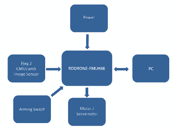
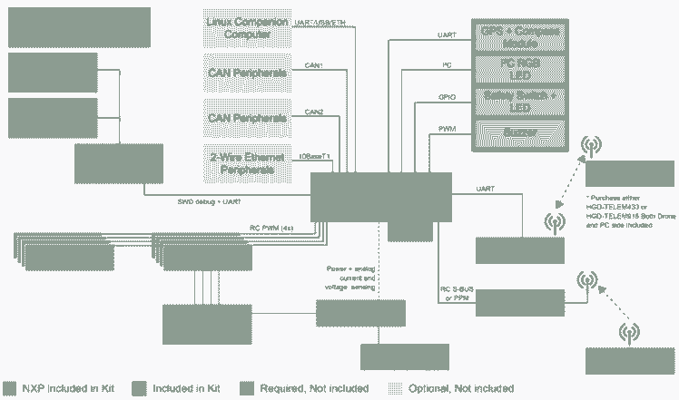
3.1.2.1. General
The architecture is the following one :
3.1.2.2. Pixy 2 CMUcam5
The PixyCam is used according the following pins :
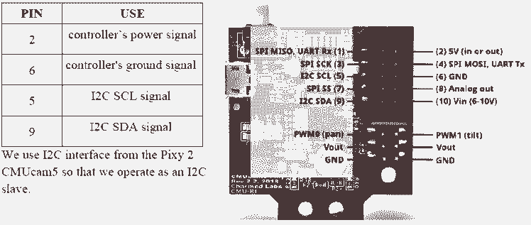
It detects and tracks lines for use with line-following robots.
With its software, PixyMon v2 we have this vision for a straight line :
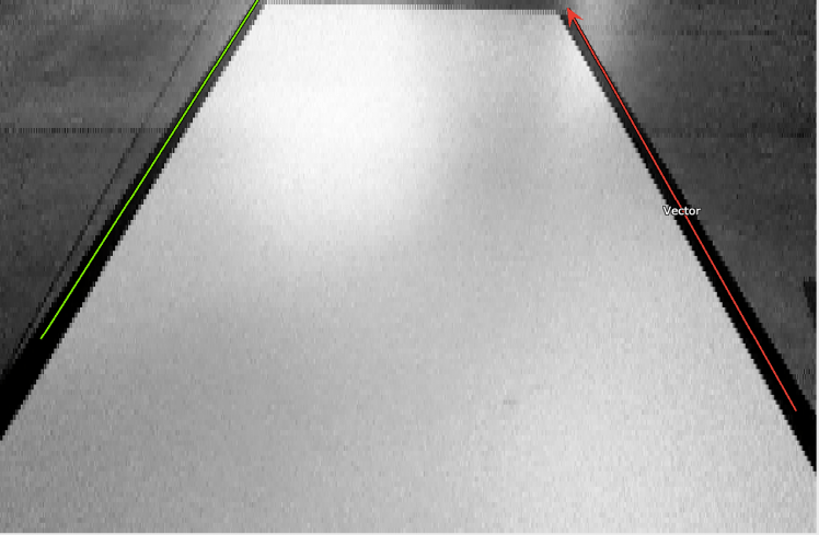
With the black and white contrast, the camera provides line, as the green one on the left, and vector, as the red one on the right.
All the controlling position is done in the nxpcup_race.cpp file uploaded.
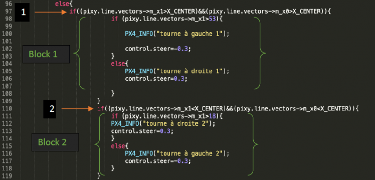
When the camera identifies a vector, the program enters in this if() condition :

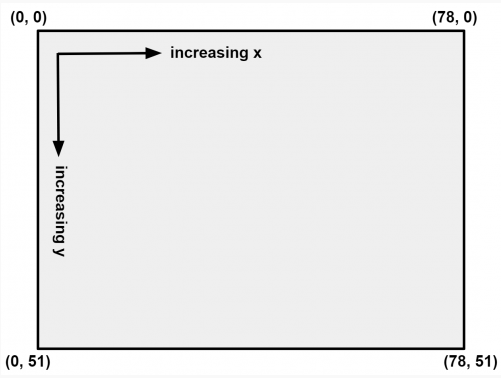
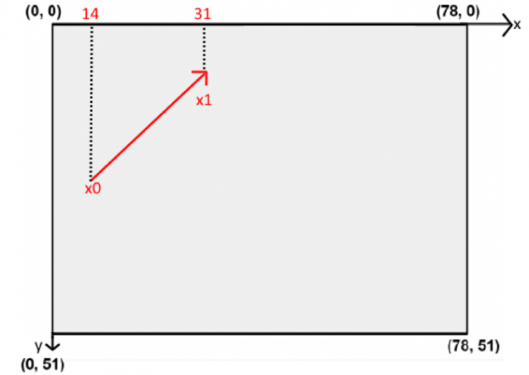
In each if() condition we operate the command pixy.line.vectors->m_X, which X is the coordinate vector of x1, x0, y1 or y0, according what we enter (see code below). Therefore, it returns the values of the coordinates so we can compare them with different constants values, chosen from this graphic below.
With our settings, for the previous straight line we have this result :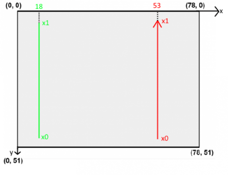
With the following code, we control our car position :
The variable control.steer is affected to the wheels orientation.
The vector/line automatically selected can be on both sides, so we coded each case.
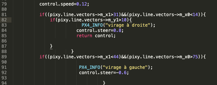
The line 1 & 2 check whether a turn is detected and the vector position.
The block 1 treats when the vector would be on the right side. If the coordinate vector of x1 is higher than 53 the wheels turn on the left side with a constant orientation and inversely for the right side.
The block 2, treats of the left side. If the coordinate vector of x1 is higher than 18 the wheels turn on the right side with a constant orientation and inversely for the left side.
Let us take an other example, a right trun :
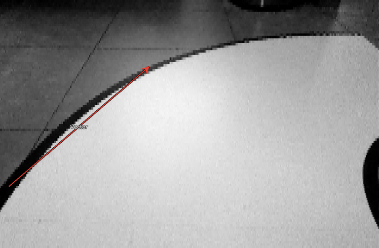
Corresponding to this case :
When the vector is near to the axis X middle and the beginning of it is close to the left of the window, it means, there is a right turn soon. But the wheels will turn until the car will be close enough to the turn.
Therefore we have this following code for a turn, treating either a left or right one :
The variable control.speed is affected to the wheels rotation.
Above all of we saw, we have the following if() condition :
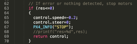
It enables to stop the car when the Pixy 2 camera does not detect any vector through the res variable.
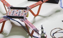
3.1.2.3. PX4 Robotic Drone FMU RDDRONE-FMUK66
The RDDRONE-FMUK66 unit reference design is the following :
 Simplified schema :
We have the following configuration :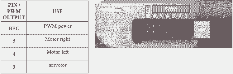
3.1.3. Assembly
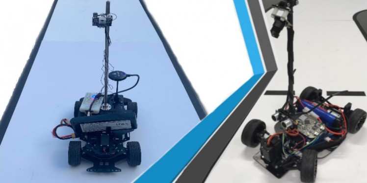
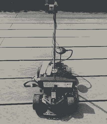
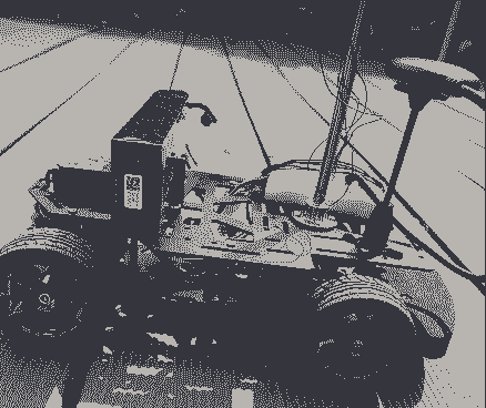
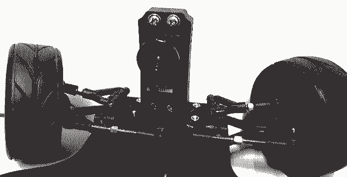
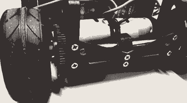
Here are the main part of the car :
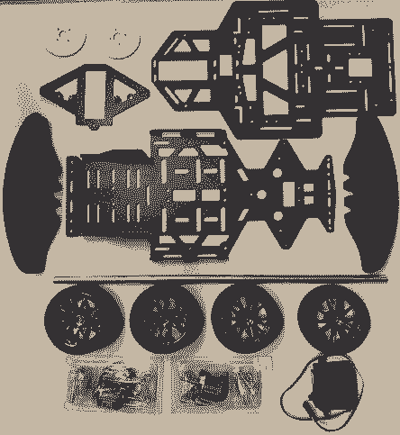
Actual shape, for the tests :

We will share some pictures of the assembly soon.
3.1.4. Issues encountered
3.1.4.1. PIXY 2 CMUcam5
The cable between the camera and the FMU board was wrongly wired.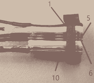 The green and the blue wire had to be exchange
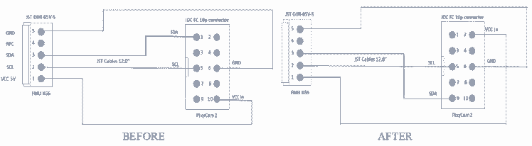
3.1.4.2. Power connection FMU – Servo
The FMU does not supply enough voltage to control the servomotor. Therefore, we had to use the following voltage amplifier, which provide a 5.5 – 26 V variation.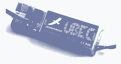
3.1.4.3. Car assembly
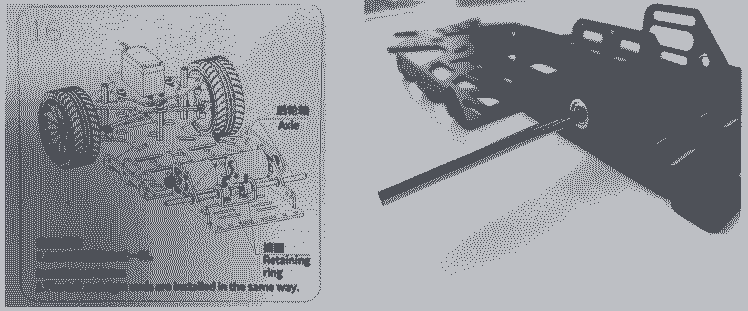
During the step 13 the gear did not fit the motor axis.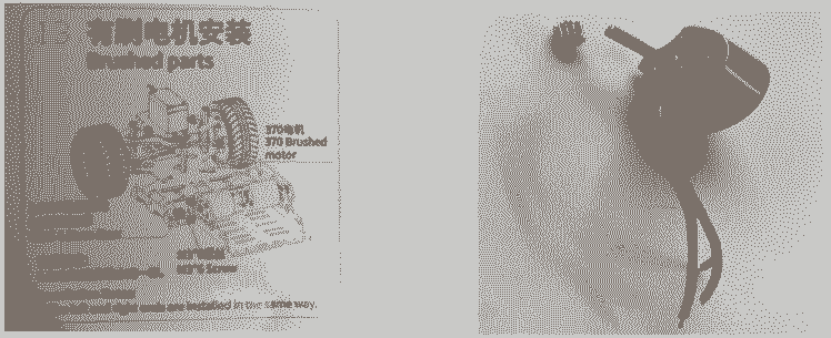 As same as the following axles for step 16 which cannot fit in the hole of the car chassis and get stuck in it.
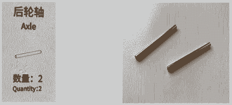
3.2. Results
Here is a video showing the advancement of the project :
or
3.3. Futur improvements
The project is in progress, we will share more advancement soon, with code and explanation !
4. Second car
The second car was taken from a NXP Cup 2018 project. Because of the issues encountered for the first car, particularly not being able to have two cars, we had to find another one.
This one was found dismounted with the skill to drive on a straight line, thanks to the code on the FRDM boards. Therefore, we had to improve the code to make it drives on the full track.
4.1. Components
4.1.1. BOM
Here is what we have :


4.1.2. Architecture
4.1.2.1. General
The architecture is the following one :
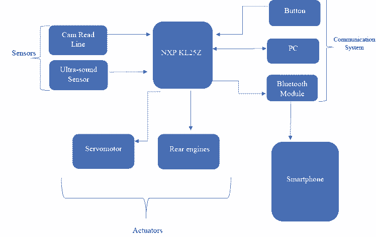
The microcontroller allows to make acquisitions of the different sensors, namely the camera and the ultrasound sensor. We then process these different data in order to send the actuators the desired commands to follow the path on which the car is placed. Then finally the communication systems are used to interact with the board, we can communicate in serial link with the PC to display the sensor data, but the idea of using a Bluetooth module to monitor this data in real time seemed interesting. The push button allows us to modify the speed values during the race.
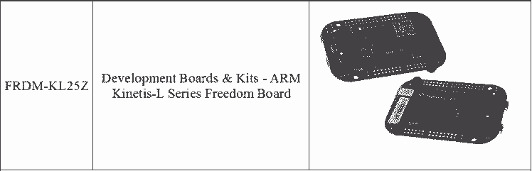
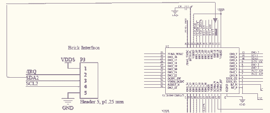
4.1.2.2. The FRDM KL25 board controller
The interface that we use is shown below :
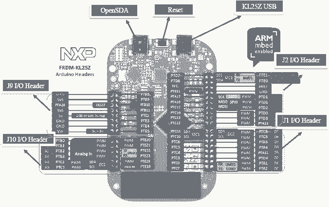
OpenSDA: OpenSDA Serial and Debug Adapter : This is a serial and debug adapter that is built into several NXP evaluation boards. It provides a bridge between the computer (or other USB hosts) and the embedded target processor, which can be used for debugging, flash programming, and serial communication, all over a simple USB cable.
Reset Button : When the Reset Button in pressed, the newest program on the Microcontroller Disk will be loaded into the Microcontroller FLASH memory. When the program has been loaded onto the microcontroller, it will then start it.
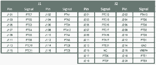
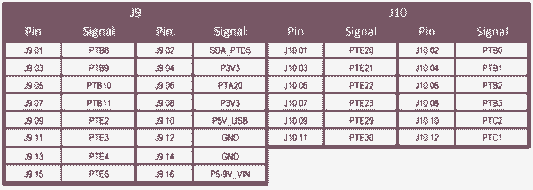
Input/Output Header : The microcontroller is packaged in an 80-pin LQFP. Some pins are utilized in on-board circuitry, but many are directly connected to one of four I/O headers. Those I/O headers make it easy to access to MCU I/O. Among them, J1 I/O Header, J2 I/O Header, J9 I/O Header, and J10 I/O Header are connected to the System Board. Here is some information about FRDM-KL25Z I/O Connector signal connections:
4.1.2.3. System Board
The system board in charge of the whole system of the external signal input and human-computer interaction, multimachine communication function, steering gear control.
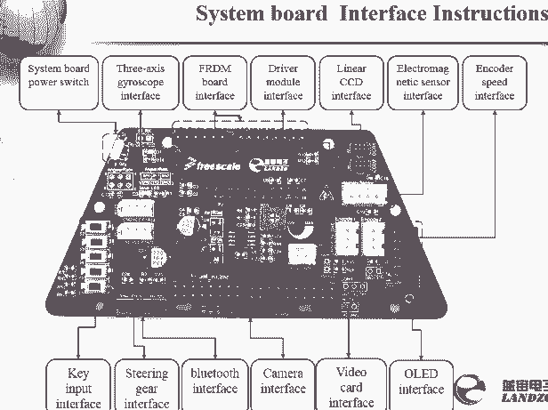
Here are the parts used :
System board power switch : Toggle this switch to power the control board.
FRDM board interface : This part is connected to I/O Header which is on the FRDM KL25 Board
Driver module interface : This part is connected to motor driver board. Because of these pins, it can be used as a bridge to connect the two boards, it means that it can pass the microcontroller's control commands to the motor driver board, and pass power from the battery to the FRDM KL25Z Board.
Linear CCD interface : This interface is connected to a CCD adapter board which is connected to the sensor. So that the data collected by the camera (located the on the sensor) could be transmitted to the system board, and then those data are passed to the system board to be processed.
Steering gear interface : Connected to the servo motor, then the command of control direction is transmitted to the steering gear.
4.1.2.4. Motor driver board
This board is responsible for the power supply to the whole system and to driver motors.
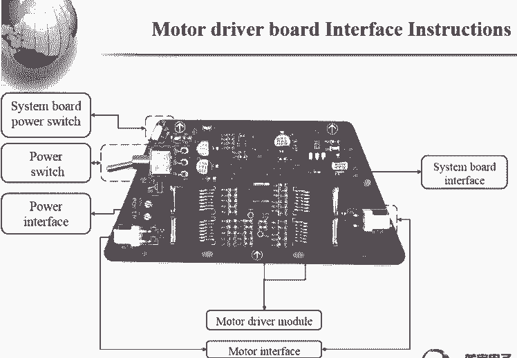
System board power switch : Toggle this switch to power the control board.
Power switch : Toggle this switch to control whether to be powered by the battery.
Power interface : This interface is connected to the battery.
System board interface : Connected to the system board, as mentioned above.
Motor interface : Connected to the motor.
4.1.2.5. Ultrasound Sensor
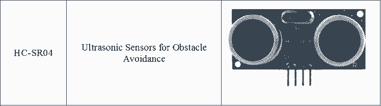
The HC-SR04 sensor uses ultrasound to determine the distance from an object. It offers an excellent non-contact detection range, with high precision and stable measurements.
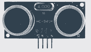
The connections are the following :
VCC = +5V DC
Trig = Trigger input of Sensor : Corresponds to a TTL input, with a duration of at least 10 us.
Echo = Echo output of Sensor : TTL signal, whose high state width is proportional to the distance from the obstacle encountered.
GND = Ground
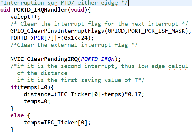
In order to perform distance measurements, it was necessary to configure two pins as GPIOs, one as a Trig input and the other as an Echo output. The output therefore corresponds to the enable signal, we use a delay() function that uses the TFC_Ticker interrupt to send a TTL signal of at least 10 us. Then we configure the GPIO that will serve as an input (which corresponds to the echo signal of the ultrasonic sensor) to trigger an interruption at the transition from the low-high state and the transition from the high-down state.
Once the second pulse is detected, the difference between the two instants when the interruptions are detected (using the TFC_Ticker counter) must be stored in a volatile variable and finally divided the speed of sound by the difference between these two instants.
Finally, by transmitting the data sent by the sensor in UART we observe that it is possible to detect an object at about 2 m, however we set a distance range of 0 to 50 cm for our obstacle detector.
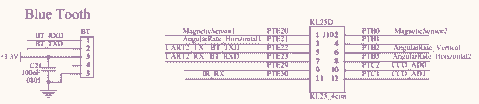
4.1.2.6. Bluetooth module
We considered using a Bluetooth module to visualize the sensor data in real time. Indeed, to debug in the situation where the car did not respect the control laws or simply to determine if the problems came from the equipment or the code, it seemed interesting to have an interface allowing to visualize the data from the camera or the ultrasonic sensor during the use of the car.
The interface used to connect the Bluetooth module to the card is shown in the figure below with its location on the module and on the board.
We therefore configured pin PTE22 ( of the KL25Z) connected to the BT_TXD connector as a GPIO and an output using channel 2 of the UART, however we soldered another connector to the Bluetooth module ( we connected pin DIO 7) because the previous pins were not accessible via the application proposed by the supplier.
Note : the use of this module is not authorized during the race
4.1.2.7. Servomotor
In order to steer our car, we have at our disposal a servomotor to steer the angle of the wheels according to the data sent.
This servomotor therefore works with the 5 volt and GND inputs of the board as well as with a PWM input that will control the desired wheel angle.
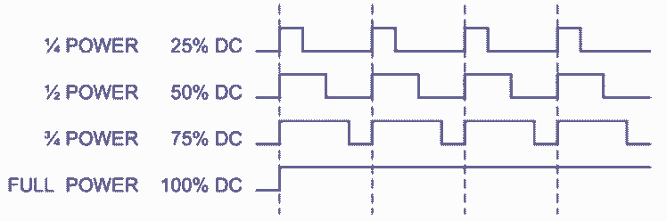
The principle of pulse width modulation (PWM) in this case is to create a clock signal whose width of the pulse is variable and proportional to the coded value. If the average of this signal is extracted, an analog value proportional to this width is obtained.
To control the servomotor, a direction angle is given by the TFC_SetServo() function given in the TFC_Servo.h library which sends the PWM to the servomotor. We had it swept through many values and found that TFC_SetServo() had to be set to a value between[1.5; 4.1] in order to be able to turn completely left and right.
The function that regulates the PWM took in parameter the desired position between [-1;1]. Therefore, we had to normalize around[-1; 1], respectively -1 to turn maximum to the right and +1 to turn maximum to the left.
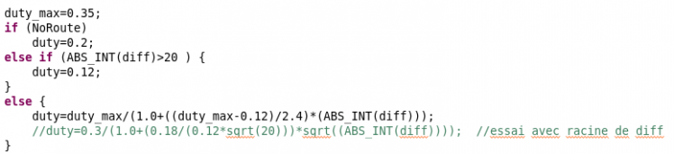
In order to have a car that is as fast as possible but stable when cornering, the need to adapt the speed according to the situation in which it finds itself has become important. To set a function that automatically determines the speed according to diff, several tests were necessary. The only two criteria are an easily adjustable maximum speed and a minimum speed for which the car is still moving.
To avoid instability, the speed had to decrease rapidly. So we quickly came to a 1/diff function, which turned into 1/(1+diff) to avoid convergence problems.
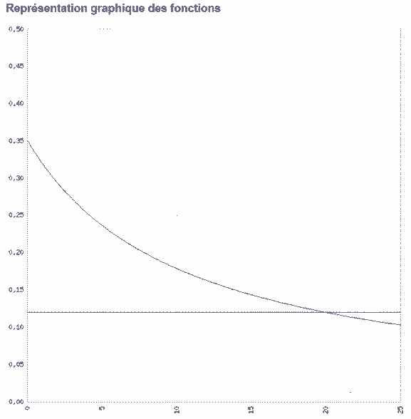
To meet these criteria, we have arrived at the following function :
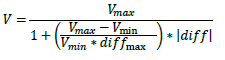
diff_max corresponding to the diff value to have a minimum speed.
Which lead to the following graph, according to the angle of steering :
Therefore, we have the following code :
In addition, in order to increase the speed of the system, we have chosen to add a corrective action on the derivative. The faster the car is, the faster the system needs to react. We therefore considered that the gain Kd was proportional to the speed.
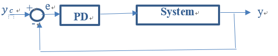
We have chosen not to add an integral action after several tests because of the difficulty in adjusting the corrector.
As a first method of adjustment, we tried the Ziegler-Nichols method, but it proved unsuccessful. We therefore decided to adjust the corrector in a more traditional way by carrying out numerous tests, first on steps, then directly on the circuit. When the system is not fast enough, it is necessary to increase the action on Kd. When the system is not precise enough, it is necessary to increase the action on Kp. If the system oscillates, it is necessary to increase Kd or decrease Kp.
As soon as you have a stable system, you should try to increase the maximum speed, then readjust the corrector gains.
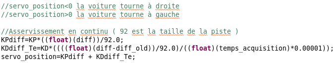
The weighting coefficients of the corrector are applied in a proportional and derived manner.

To protect the servo motor, a saturation is applied after the corrector, to avoid turning the wheels more than possible.
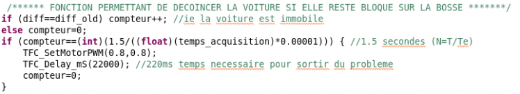
To get through the bump, if the arrival speed is not sufficient (which can happen when exiting the bend), the car may stop on the coast. This function allows you to boost the car if it is stationary for more than 1.5 seconds.
4.1.2.8. The rear engines
In order to propel our car, we have at our disposal 2 continuous engines, one for each rear wheel. As a result, the car's speed can be adjusted by also applying a PWM signal to the motor connections.
Thus, the function TFC_SetMotorPWM() provided by the TFC_Motor.h library allows us to set this PWM sent to the motor, which allows us to set both speed and direction. In this case, when we will change the pulsation it will influence the speed of the car.
 As with the servomotor, the function normalizes the motor functioning over a range [-1; 1], where the positive part is forward and the negative part is reverse.
4.1.2.9. The camera

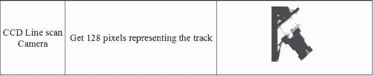
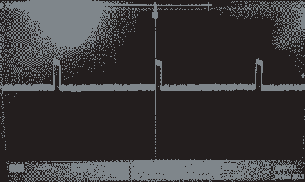
As the car travels on a white track bounded by black lines, the detection of the road is done by the detection of its black lines. To detect the difference between white and black, a contrast table is created parallel to the pixel table. The maximum contrast of this table will indicate the presence of a black line.
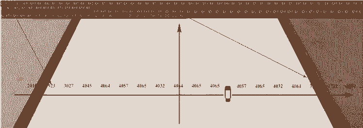
The sensor captures 128 pixels and stores them in a 128-bit array called LineScanImage(). These numbers received represent the track color: about 4000 for white, 1000~3000 for black.
To avoid considering small variations in contrast as a trace on the track, a constant (Threshold) is defined corresponding to 80% of the maximum contrast below which a contrast of will not be considered as a line. This constant is recalculated at each acquisition to be able to adjust approximately to the ambient brightness if it changes. However, to avoid that this constant falls too much, especially when the car meets an intersection, for which there is no contrast (no lines), a minimum value equal to 40% of the initial maximum contrast is also defined from the beginning.
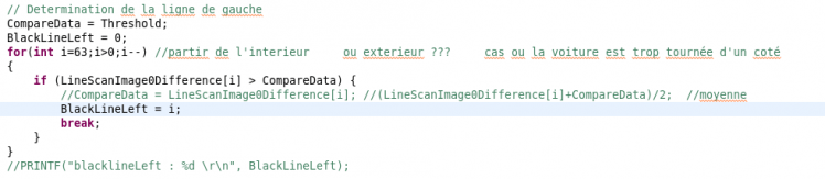
To determine the position of the lines in relation to the camera centre, the contrast table is run from its centre and the values exceeding the previously defined Threshold constant are searched in one direction and then in the other. The indices of these values in the table will be retained as the position of the black lines.
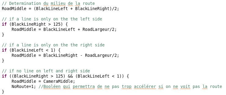
From the position of these lines, the position of the middle of the road is determined, which is generally between the two lines, with some exceptions.
When the car enters a bend, very often the middle of the pixel line seen by the camera leaves the track. The car would thus confuse the right and left lines and make unforgivable steering errors.
To correct this problem, a function analyses the difference between the position of the two lines, if this difference is very small, it means that the middle of the pixel line seen by the camera is on a line. In this case, the car remembers the previous calculated mid-point and continues to turn in the right direction.
This function even allows the car to leave the track very slightly and still return to it.
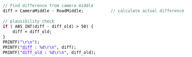
When we are of course from the position of the middle of the road, we can calculate the difference between this middle and that of the camera, which will allow us to control the system by trying to make this value null.
4.1.3. Shape
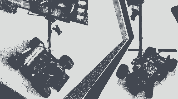
4.1.4. Issues encountered
4.1.4.1. Servomotor
TFC_SetServo() had to be set to a value between[1.5; 4.1] in order to be able to turn completely left and completely right and not between[-1 ; 1]. Therefore, we had to normalize our domain range.
4.1.4.2. Configuring the camera
Acquiring the data from the camera is very important. At the beginning, we had trouble receiving them because of our camera settings. We had to adjust the camera parameters to process the data.
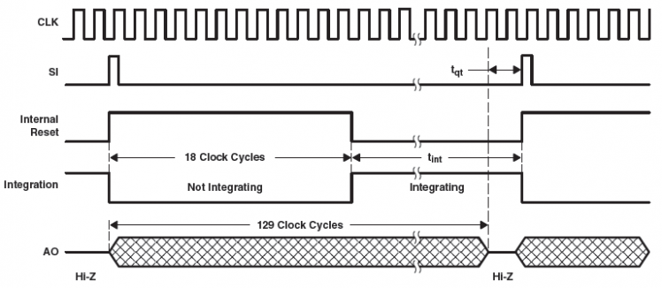
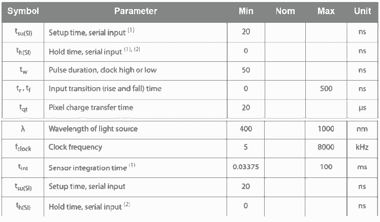
As we can see on the figure, the camera’s routine is influenced by several delay, for instance, the integration time is primordial because it fixes the time where the camera is exposed and thus it imposes the minimum delay between acquisition of two sample.
Moreover, integration time is the delay influencing the luminosity contrast, this was the first parameter we fixed.
This table found in the datasheet of the Camera provides us to fix a minimum for the Integration Table, and also ensure that the Tqt minimum delay is respected.
4.2. Results
We will upload a video soon, showing our advancement/results.
4.3. Future improvements
We have now to code for the optional extra disciplines : Obstacle avoidance,Speed limit zone and Emergency braking.
Moreover, we will upload code soon.
Schematics, diagrams and documents
Code
Credits
Related products


Leave your feedback...