

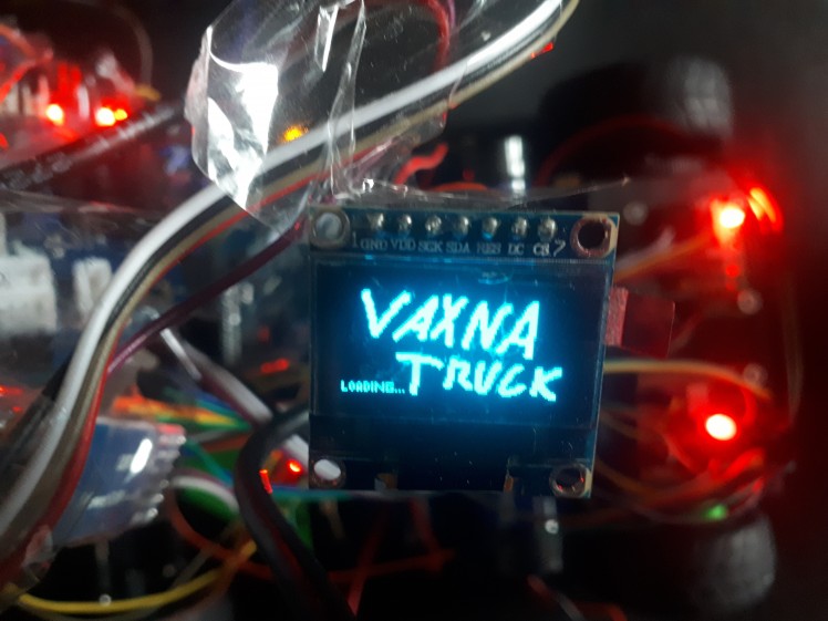
Nxp Cup - Autonomous Racing Car
Made by VAXNA / 3D Printing / Robotics / Vehicles
About the project
Autonomous cars are starting to rule world. So let's try to make our own and go to race!
Project info
Difficulty: Difficult
Platforms: NXP
Estimated time: 5 months
License: GNU General Public License, version 3 or later (GPL3+)
Items used in this project
Hardware components


View all
Software apps and online services
Hand tools and fabrication machines
Story
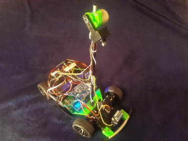
Me and my friends have decided to go again to NXP Cup this year. We already had some knowledge from previous one, so we decided to make something more difficult. So we will be making a new main board, camera on servo motor, bluetooth communication and much more.
About NXP Cup
Why?
NXP Cup is competition for students of high schools and universities, which is about getting a real experience of hardware, NXP microcontrollers and having fun.
Where and when?
Competition is splitted into two parts. First is local and second is global. Our team will compete in local part in Czech republic. Global part should be happening in Romania. Those parts were planned on March and May, but were postponed, because of current coronavirus situation.
How?
Both parts will have some content, just the final part will take two days and the first part will take just one day. Each part have five disciplines:
- Figure 8 - The goal is to complete as much as possible tracks on track which looks like number 8 in 60 seconds.
- Speed limit - The goal is to slow down when car sees slow down sign and speed up back, when it sees speed up sign.
- Obstacle avoidance - The goal is to don't hit white cube which will be placed on track and don't leave track while avoiding the collision.
- Emergency break - On the track will be placed again white cube, but this time the goal is to stop in front of it.
- Timed race - The goal is to complete track in shortest time possible. Max 500 points.
The goal is to finnish this with car which is programmed by students themself. All tracks are roads wide about 60 cm, which have black lines on edges.
Camera
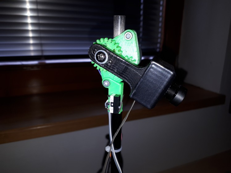
This is the most important thing of whole vehicle. The camera is used for navigation of car between two edge lines of track. It is even stated in rules that it should be main thing that is used for navigation of car. We are using monochromatic line scan camera. This means that our camera can see just one line of black, grey and white pixel, aka it has resolution 128x1. This resolution is compensated by high possible framerates and also by good light sensitivity.
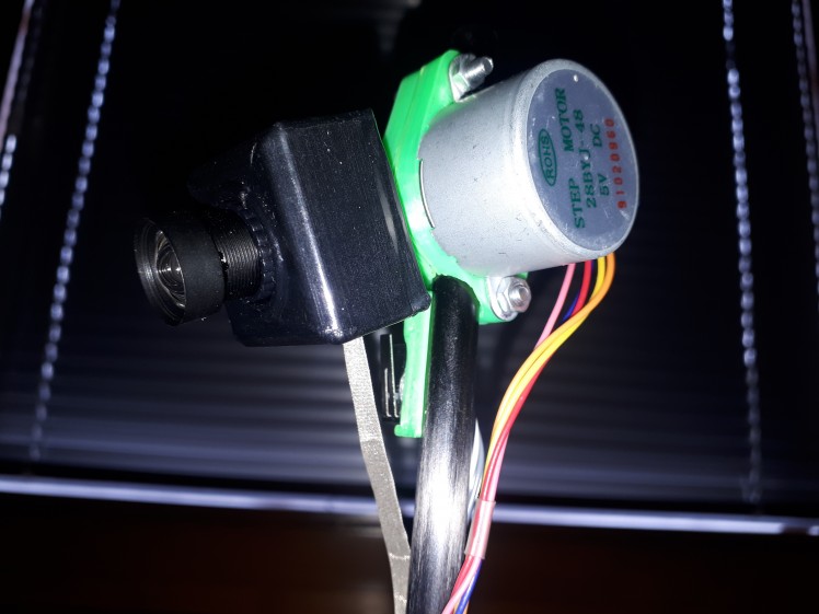
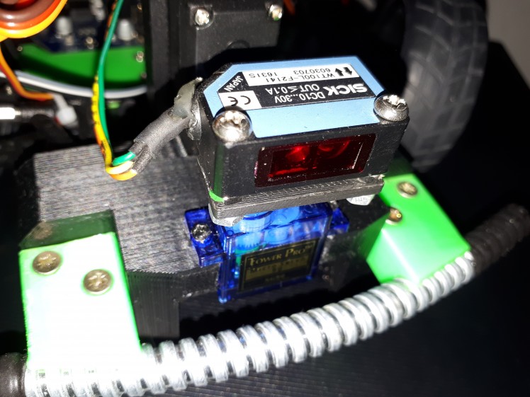
While we were racing previous year, we had found out two things. First is that light doesn't come only from front of camera, but also from back. This happens, because camera chip is placed on thin PCB, which lets come light through. So to mitigate this problem we 3D printed black camera case and now it looks cooler too!
Second problem was, that we were moving camera up and down a lot. We were doing this because we were trying to find right distance, where camera captures turns correctly and doesn't capture car itself and we found that also for different type of tracks best position differs. Next issue was also that if we accidentally hit the camera we had to found right position again. So we added stepper motor with gears with 1:2 ratio, which make our camera move faster. Also you can see at the image that we added end switch. Because servo motor doesn't itself provide any informations about it's initial position. When our cars boot up, we always move it down to the position where it touches the end switch. From that moment we know where is our camera looking at.
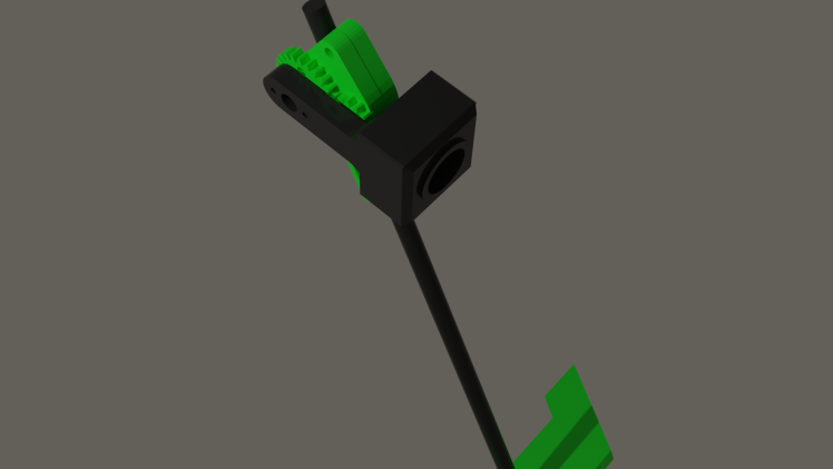
Here you are able to see 3D render of all 3D printed parts (just the stick isn't 3D printed and was added to make complete looking image).
So lets look more at the hardware and software side. Our goal is to capture as much as possible images per second while keeping good contrast. If we wouldn't have good contrast, then we would either have issue with having image too dark, so there wont be possible to see anything on it or it would be too bright it, so you wouldn't be able to see anything as well, but in this case everything would be white. Also we can't have our exposure long, because it would limit our framerate. Framerate is calculated as:
- FrameRate = 1 / Exposure
It is partially possible to fix those problems by normalizing values. Lets say that we have black color with value 0 and white with 1. We take our oversatured image which have lowest value of 0.8 and highest 1, this gives us value range of <0.8, 1> which we are going to map into <0, 1>. By this our colors change from 0.8 to 0; from 0.9 to 0.5; and from 1 to 1. By this really simple process we got normal looking image without saturation, but it also brings a lot of noise into the image, so it makes searching for lines a lot harder. And if we would add 25% light into our scene, then captured image would go into <1, 1> range and we would be unable to extract any data from this, not even noisy ones.
So, lets get back to the exposure and how to set it right. Our goal is to achieve biggest possible contrast possible. Contrast is calculated by following equation:
- Contrast = LightestColor - DarkestColor
We achieve biggest contrast when lightest color is pure white and darkest color is pure black. Our camera is linear sensor, so this means if we increase exposure by 50%, then both darkest and brightest value should increase by 50%. Our goal is to get average color to 0.5. Consider following examples <0, 0.1>, average of those values is too low (10x), so we can say that we need to divide exposure by 0.1; <0,1> average is 0.5, so we are perfectly fine and don't change anything; <1,1> average is too high (2x), so we divide exposure by 2. Based on this we can create following equation for adjusting exposure.
- NewExposure = OldExposure / (LigtestColor + DarkestColor)
And that's it, everything works. Well almost.
You can go with your car anywhere and colors looks just fine. Atleast untill you go to room which isn't lighted by sun, but by fluorescent lamp or something. You would start to see a huge blinking, even while the lights are shining light for your eye just as usual. Why does that happens?
Our lights are powered by AC power, which follow sinus at fequency of 50 Hz. Which looks like this (x axis is in seconds):

You can see that it is really running at 50 Hz, but peaks are at 100 Hz. Also what really matters for light isn't voltage, but the power, which looks like this:

We can now see the 100 Hz really clearly. So how to fix this problem? We will need to get our sampling frequency synchronized with the power frequency, so only aviable frequencies which makes sense are 100, 50, 25, ... Hz. But we want to stay at highest possible frequency, because the lines are really thing and we can miss them really easily if we don't take photos often. But lower frequency like 50 Hz is useful in low light scenario, where we need our exposure over 10ms because of low light levels.
So lets look how to implement this. We would need to take frame each 10ms with our exposure. But we reach into problem here. Start and end of frame capturing are linked together into single event.

As you can see on the image we send SI pulse and read pixel data one by one by sending CLK pulses. But as you might see, after reading 18 pixels of our image there begins new integration (capturing of image) which we want to happen after some more time (integration of previous image took 6ms and we want to keep our sync at 10ms, so we want to wait 4ms more). We can fix this by clearing CMOS by dummy read (we ignore content and do the read as fast as possible). So our final reasult looks like this: We integrate the image for 6ms then read it and process it, imediatly after this new integration begin, so we read the sensor after 4ms, but ignore the data. And after this new integration with lenght of 6ms for our real image begins.
Of course there can be case that the track will be lighted by some better lights. Some lights have capacitor which decreases this flashing or they can store some of that energy in term of heat and light for some time. Then the light power will look like this:

Or it can be just be under sunlight, so it would be perfect line. When we got enough stable light output like this, we can remove the code to fix blinking and try to get more than 100fps. But we should keep always around this piece of code as the competition happens in enviroment we don't know.
Let's look how to program this. K64F have aviable four PITs. PIT stands for programmable interrupt controller. It is really simple device in which you set after what period you want to trigger interrupt and it will trigger it. Interrupt is usually small function, which doesn't get executed by other code, but it gets executed by interrupt controller. It is device, which can interrupt executing of current code, save it's state and execute some that interrupt function when some event happens, like PIT waits for time we set it to wait.
We will need two PITs for our camera. One will be for 10ms clear interval and second for setting integration interval.
Let's look at sample code of interrupt handler:
- extern "C" {
- void PIT_CHANNEL_0_IRQHANDLER(void) {
- if(PIT->CHANNEL[0].TFLG & PIT_TFLG_TIF_MASK) {
- PIT->CHANNEL[0].TFLG = PIT_TFLG_TIF_MASK;
- // interrupt code goes here
- }
- }
First thing we need to write is extern "C", beucase C++ doesn't follow old school low level code practices, which can make it hard to find our interrupt function. This toogles it to old C mode, so everything will works fine. Then it is follow by function declaration, it always have to have void return type with void parameters, so the function doesn't return any value and doesn't accept any too. The channel sets which PIT should be used, in this case we are using PIT0. First thing the function do is that it check if it was executed by the interrupt and if it wasn't then it exits. If it was, then it clears interrupt flag. This flag causes interrupt controller to trigger this interrupt and if it won't be cleared, then it would end in endless interrupt loop. This is followed by our real interrupt code.
Now we need to look how to detect lines from image we got. We are looking for black line with white area next to it. I have first thought about thresholds and search for area, but this didn't worked really well. The best way I found out is use of derivation. Derivation will give peaks at places where is rapid change for black to white or vice versa. It works great, but to achieve best quality detection we need to use averaging. At first someone might get idea that the way to do this is to average adjacent derivations, but this won't work. Let me show you why:
- Derivation = (Der1 + Der2 + Der3)/3
This equation equals to next equation:
- Derivation = ((P1-P2)+(P2-P3)+(P3-P4))/3
And when we simplify that, we simply get:
- Derivation = (P1-P4)/3
This won't get us rid of the noise. So I came with different approach. I average first group of pixel, then I average second group of adjacent pixels and perform derivation on average of those groups:
- Derivation = (P1+P2+P3)/3 - (P4+P5+P6)/3
If the result is close to 0, then it means there are no lines. If the result is away from zero, then it means that there is line somewhere. Based on if the derivation is positive or negative you can detect if it is change from white to black or black to white.
Stepper
The stepper motor is controlled with use of 4 signals. They are called A,B,C,D and each of them controls one coil. I am using motor 28BYJ-48 for which is best working half step mode, which you can see on picture below. There also exist full step mode, which I tried, but I had feeling that it leads into worse performance. Half step mode consist of 8 different combinations of ABCD (you can see that everything on image repeats after 8 divisions) and half step mode is using just 4 combinations. Motor is moved forward by sending pulses from left to right and in opposite direction by sending them from right to left.
When the car boots up, then position of motor depends on the position where the motor was before car was shut down. But it isn't good to get the position by this way, because someone might apply huge enough force to the motor by hand and move it into different position also this position saving would slowly destroy flash memory of controller. So best way is always at car boot send those pulses in direction which move the camera down and at each move check if the camera had hit the end switch (that is small switch mounted under camera and is defining the lowest position of camera, also the angle under which the camera hits the switch must be known, so we can do all calculations we need). After the camera hit the end switch, the switch closes and send signal to out microcontroller, this stops moving of stepper and says that we are now at position 0, aka start position.

Bumper
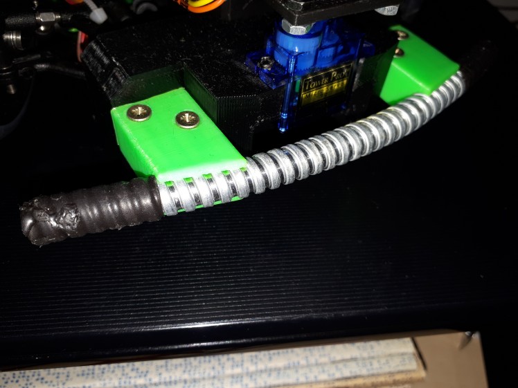
We learned from previous year how much is bumper important. We have collided with walls and various objects many times and almost totally broke our car. So this time we have added bumper from flexible piece of tube, which holds on massive 3D printed block, which we also use as holder for our laser. The tube is able to absorb part of the collision and rest is transfered through the massive block to our car, so the collision isn't handle only by edge of the car.
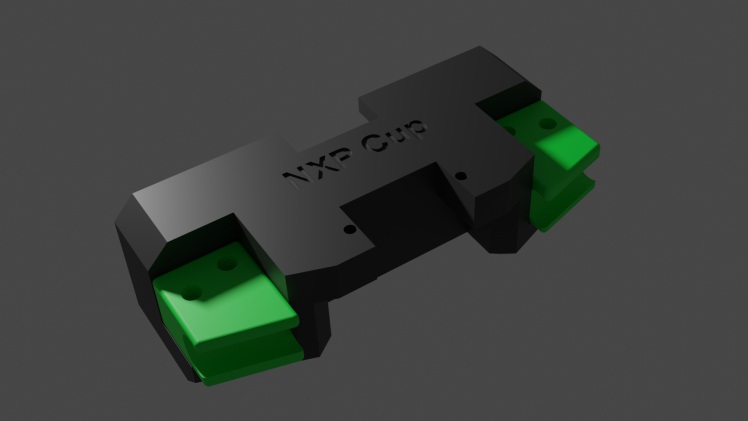
Here is 3D render of bumper, as you can see it is really massive and it also includes holder for the laser.
Laser
This part is needed because of obstacle avoidance cheallange. Goal is to dodge white cube, which will be placed into the track. Our plan is to find this obstacle with laser, which will be rotated around with servo motor. This is first step, which is very acurate with giving information if obstacle is close, but it isn't able to give perfect position. After we find the obstacle we will use camera with stepper motor to properly scan it's position.
To make this part working it is needed to be connected directly to battery for maximum voltage also there is need for optocoupler as this laser sensor outputs aproximately battery voltage, which is about 7.2V. But K64F is able to handle 5.5V at maximum. So we power optocoupler diode with this voltage, which have it's current limited by resistor, so it performs fine. This diode lights on transistor, which get's opened. This transistor is powered by 3.3V, which is fine voltage for K64F.
Schematics for this simple circuit is here:

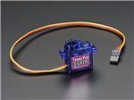
Servo
Both laser and steering needs servo. It is controlled using PWM with speed of 50 Hz. The position of servo motor is changed by duty cycle. It is usually 1ms for minimum and 2ms for maximum, but it is better to calibrate each servo invidualy and find their center position as well as step size for duty change.

Also one might think, that it would be good to use servo for moving camera up and down instead of stepper, but I decided to don't do that. Servo might be faster and easier to control, but this comes at some price. And that price is precision. Servo motor is actually made of DC motor, just like that one in those small RC cars or other kids toys and potentiometer. The motor rotates and rotation is outputed from motor via gearbox to which is attached the potentiometer, which is used for detecting of position. The issue is that there might be some small dust, nonlinear precision of resistor element, low precision controller, etc in the potentiometer. This can lead into sudden unexcepted jumps when trying to move motor slowly or in motor not moving at all. It can't just be used for setting of exact positon (atleast those cheap servos can't), so I choosed to use stepper, which is slower but more precise.
Encoder
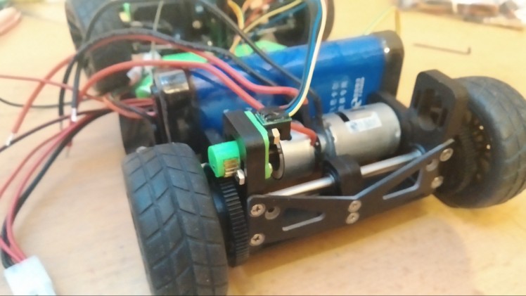
We have learned from previous year, that it is very useful to know venhicle speed. It can be used to regulate what power we want to pass into motors, mainly at start where we want to pass maximum power till our car gets at desired speed. Also it is very good for challanges where we want to go really slow. There can happen that if we go into turn, then there is aditional friction which can make our car stop and will hold it for ever. So if encoder tells us that we are stuck, then it can put additional power into motors, so we will start moving again.
Encoder produces two singnals known as phase A and phase B, we were lucky and our cotroller already contained hardware module for quadrature decoder (encoder data reading), which gives us ability to read encoder at high speed with 0% CPU use.
Decoding is very simple, if signal leads on phase A, then the encoder is moving forwards.
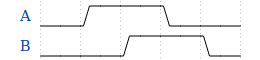
If signal leads on phase B, then encoder is moving backwards.

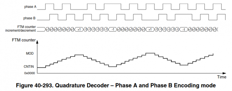
It actually works by incrementing/decrementing when there is edge on any phase. This implementation is mostly important if you are planning to use controller without hardware decoder and you need to code your own is software. There are eight possible states which you can find in K64F documentation on page 1072 or you can extract them from graph below:
On the hardware and software side it works all really simply. We are putting into the motors PWM signal, which regulates how much power can go into them. But sadly power isn't proportional to speed. So we get our current speed using the encoder and by this we can calculate error from desired speed. Then we pass this error into PID regulator (this stands for proportional, integral and derivative regulator), which adjusts power which should go into motor to achieve our desired speed.
Also to make work everything correctly, then we would need to use PIT, just like for camera. I choosed to use PIT3, which will be executed 20 times per second, each time it is executed, it will read how far did the encoder moved form last read, pass this value into PID regulator and update motor speed. We are using this PIT, because if we would be just reading and adding together the values, then we would get distance. To calculate speed we can use this primary school equation:
- Speed = Distance / Time
In our case time will be always 50ms and distance will be the amount that the position of encoder has changed by last read.
Display
We are using display which comes with the kit. It is SD1306, which is controlled with SPI. It will be used for different menus and diagnostics information and it should make control of the car much more easy. For controlling the display we use u8g2 library which is really easy to port into other devices, event that it was made for arduino and is really useful for easy work with basic texts and bitmaps.
Communication
While we will be racing then it is against rules to attach any computer or wireless device to the car. So when we will be racing, then we will use OLED display described above together with buttons to control car. But when we won't be racing and will be debugging, then we are going to use two things for debugging.
First is over USB connector. It allows us to program microcontroller and also it gives us ability for stable and fast communication with device. Second is bluetooth. We will be using it when we are testing car on track, so we wouldn't had ability to keep USB cable connect because it is too short, gets into wheels or can disconnect easily.
Single MCU architecture or multi MCU architecture?
This question might be kind of difficult and depends on a lot of things and correct architecture design. But first it would be good to know what is actually MCU. MCU stands for micro-controller unit. It contains chip which can run code, process data, etc and it also contains pins with a different functions (most know function is Input and Output). Let's look at adventages of each those possibilities.
Signle MCU:
- lower price
- no wait for data delay and communication CPU overhead
- smaller space usage
Multi MCU:
- higher processing power
- more aviable I/Os
I have choosen for my project signle MCU architecture and I will explain very soon why.
First reason is very simple. I use what I got into my hands. I had ability to use KL25Z microcontroller or K64F microcontroller. (I think that those are most common MCUs used in the competition, so this small guide should be able to help others with choosing correct MCU too.) I had easier ability of K64F and also more replacement MCUs of that type if anything broke. Also it was way more powerful than KL25Z. It have 2.5x faster CPU speed, 8x more flash, 16x more RAM. Also it contains instructions for dividing, float point calculations and faster intrrupt execution, so the CPU is actually more faster than 2.5x. Also it got some other good stuff like hardware support for encoder, which would be taking a lot of CPU in KL25Z.
With this processing power I think it is unnecessary to include two K64F. But let's look into it in more detail and consider what we did and some other stuff.
Here is sample image of dual MCU architecture:
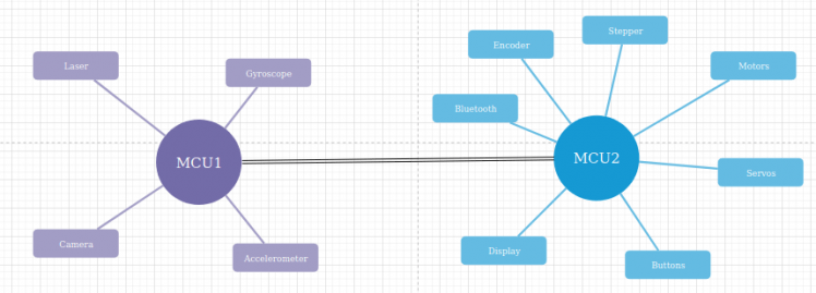
At first it looks really nice, but when we would start to moving it into reality, then issues would appear.
Goal of MCU1 is to get data from accelerometer, gyroscope and camera, do all needed calculations needed to know correct speed of each motors, position of servos, etc. Also it would have access to laser, so at beggining MCU2 would set what track will the car be racing on and based on it, it would ignore laser, set speed to zero when it sees obstacle or dodge it.
MCU2 would be using all those data to set correct servo position, get data from encoder and set motor power based on desired speed from MCU1. Also it would control stepper for moving camera. And also it would have include all the communication over bluetooth and creating UI with display and buttons.
Everything seems nicely separated and processing should be nicely split, but lets look into hardware prespective how it will all work.
Fastest way to communicate between those two devices is over SPI bus. Hardware limitations for frequency of SPI bus on K64F is 30 Mhz and 12 Mhz on KL25Z. This means 3.75MBps or 1.5MBps. Those aren't that bad speeds, but those processors communicate with their registers at 480MBps or 192MBps, so the difference is huge.
Let's say that MCU1 decide to change speed of motors. It would need to check if the SPI bus is free or else wait till it will be free and this cost CPU. Then it would transfer at those slow speeds over SPI bus + it needs to include control bytes, so we know what those values mean. After it the MCU2 would need to check if it received anything and what does it mean and then finally set the motor speeds. The main benefit is in calculating of PID on secondary MCU, so offloading MCU1 for camera data processing, but it is just about 5 FPU calculations, which K64F supports natively and they are really fast. The setting of motor PWM is question of two 4 bytes write into memory, which happens at those 480MBps. The PWM is generated by hardware and thus it doesn't put any load on CPU.
If MCU1 had motors and encoder attached to itself, then it could do FPU calculations itself and then do simple write to memory to set motors speed, which would take about same processor time as to transfer those data into MCU2.
When we now talked about motors, then we can focus a bit about the encoder. It actually doesn't use any CPU as K64F have hardware support for it, so no matter how fast it is rotating, it will still use no CPU. But if you are planning to build it with KL25Z, then it migh be actually useful as it doesn't have hardware support for encoder. Because of this no support it would have to use interrupts to add this support, so it means atleast 30 cycles for interrupt, 4 interrupts per disk hole, 10 holes per disk, 100 rotations of wheel per second. Of course those are just sample numbers and they can be for sure higher or lower. But they evaluate to 120 thousand cycles of those 48 milion aviable, those numbers don't sound actually that high, but they might be interesting to offload into MCU2. But this isn't my case as I am using K64F.
Servos are just same as motors. They too depend on PWM, which is just two writes into memory and also there is somewhat reduced usability of offloading PID calculation, so this is actually even more useless.
Let's look at display and buttons. They at first also sound really cool to offload them into secondary MCU, because that would again give more processing power for processing camera data. But sadly this again become useless, because we don't really need those buttons and display when car is riding and that's the moment when the processing of camera data happens. So it's always running either dipslay with buttons or camera with sensors. Ofcourse that there is case when we want to debug our car, so we would like to see display displaying results from camera, so both should be running, but in this case we don't care about drop of fps even into 20fps, because it doesn't really matter to our eyes and will give us good enough impression.
Next thing is bluetooth. If it will be used just for reading motor speeds, encoder data and servos data, then it is usefull, because all those data can be cached in MCU2 and just sended to another bluetooth device without talking to MCU1. But if you decide to send over bluetooth other stuff, such a raw camera data, then it isn't much usefull anymore, because MCU2 doesn't normally have access to camera data and would need to ask MCU1 for them. Which would need to send it over SPI to MCU2, but there isn't really much difference if the bluetooth module would be hooked directly into MCU1 and would send the data ove UART to bluetooth module.
Last thing is stepper motor. It's offloading can be usefull if we would want to move it's position by bigger ammount if we are driving. But also it would be need to the case that we wouldn't care what is currently position of motor and this doesn't happen really often when we are driving, atleast not in our case. Otherwise moving motor by one step is just two writes in memory and we know exactly where our motor is with no delay.
So we are now able to see overall result. It is somewhat a bit negative to neutral, but a bit positive for KL25Z. But it is also increasing cost to double, while it is just better to use single K64F. Also there is need to program two chips at once and debugging them at once too and this somewhat increase testing complexity. So now you are able to see why I choosen single K64F.
But as I said, the dual MCU have adventage in more I/Os and there I hit problem with my single MCU build. And that problem was also somewhat created by K64F having less I/O pins than KL25Z, so lets look at my architecture.
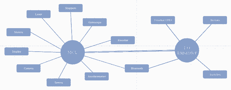
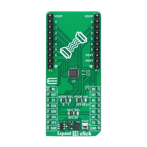
I was able to connect all components, which requires high speed communication directly to MCU. To the MCU I also connected 16 ports I/O expander over I2C, which is shared with gyroscope and accelerometer, so it doesn't use any more pins in MCU. To it there are connected only components, which require very low check rate such a switches and buttons and they also don't require to be checked while the car is driving, so I2C bus will be fully free for gyroscope and accelerometer. Also there is connected status and enable pins of bluetooth module, which are only needed to be used once for module configuration at car boot. After all this I was left with next 5 unused pins, to which I solder header and might use them for external components.
3D-Part Manufacturing Process
In a modern age 3D printers have become very useful tools for hobbyists. It is almost necessary to have one if you want to work on some home project. But when you have one, printing is the easiest part of manufacturing process because before you even start printing you must make a digital 3D model.I have two 3D printers at home, obviously the cheapest on the market because I’m a student with a minimal income :D, but that just mean that even with little money you can make BIG things.If you want to design your own parts and print them you need these 3 things:
- 3D modeling software
- 3D slicer
- And 3D printer
Which 3D modeling software you should use depends on what thing you want to make. For example if you want to make a statue you probably shouldn’t use engineering software but one that would have tools appropriate for operations that you will perform. My favorite program in which I create my digital models is FreeCad. It’s powerful, open source and easy to use. Final product of this part of making is an .stl file which contains your digital model. Actually, if you want to replicate this project and tune your NXP car you can skip this part, because I actually made these .stl models so you can just download them.Next part in a manufacturing process is a 3D slicer in which your digital model is sliced into thin layers. If you seek for a professional slicer with tons of options I can recommend you Cura. Here you can specify printing process and choose properties of your final product. Chosen printing speed, temperature and other “details” are important and will ruin your results if you mess it. Sometimes it just need patience and learning from mistakes. When your model is ready to make, slicer will generate a g-code file which is basically a finite program for your 3D printer.
Custom parts assembly Instructions
- Before you begin, make sure you have exactly same model of your NXP car (Alamak car kit), otherwise these parts won’t fit
- Download stl files
- Open them your 3D model slicer and select suitable printing properties at your discretion
- Print them all (material doesn’t much matter, but I used both PLA and ABS)
- Assemble them correctly. Let the pictures guide you to success.
You can check all models on https://www.thingiverse.com/thing:4319473
Main board
When we had all other hardware planned, then we had realised we got problem. Default main board supplied with car kit had different pinout than we needed and haven't supported all our hardware. Also we wanted maximum compute speed for this card, so we decided to use K64F instead of KL25Z controller. And those controller had different pinouts, so we couldn't fit even the brain of our car into main board, so we got into the design of our new main board.
For the design I used EasyEda which is really simple tool for making schematics and turning them into PCB layouts. Also they cooperate with JLCPCB, that is company which makes cheapest PCBs on market and also they offer discount on first order.
We had added there important parts which were on old board such as small powersupply for generating 6V, which power servo motros. Or buttons, but we modified them so they don't behave as single analog element, which is a bit harder to get the presses from, so we couldn't use classical debounce and there is also issue that there can be multiple keys pressed which makes extraction of real value a bit hard and also it would need use of A/D translator which we are using for camera, so it could decrease maximum fps.
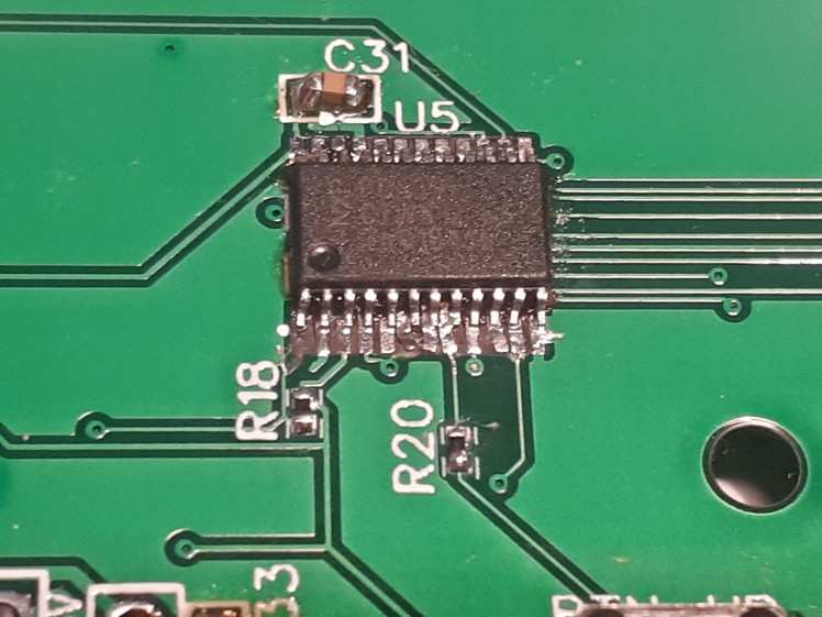
Then we added some new parts, such as external I2C for easy addition of I2C modules, gyroscope for better calculation of car movement, switches and proper display mount. And because we had added all that stuff and we used controller with less pins we had also to add I/O expander for increasing amount of aviable I/O ports.
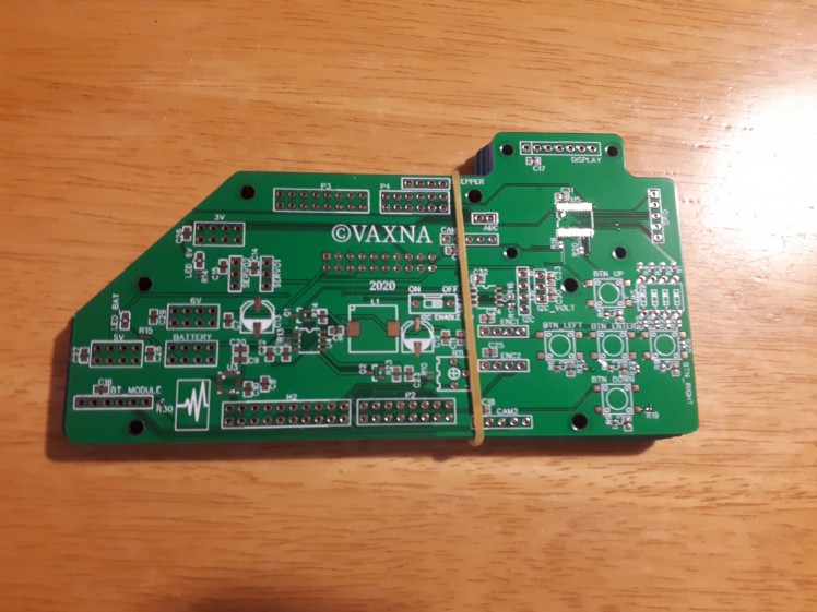
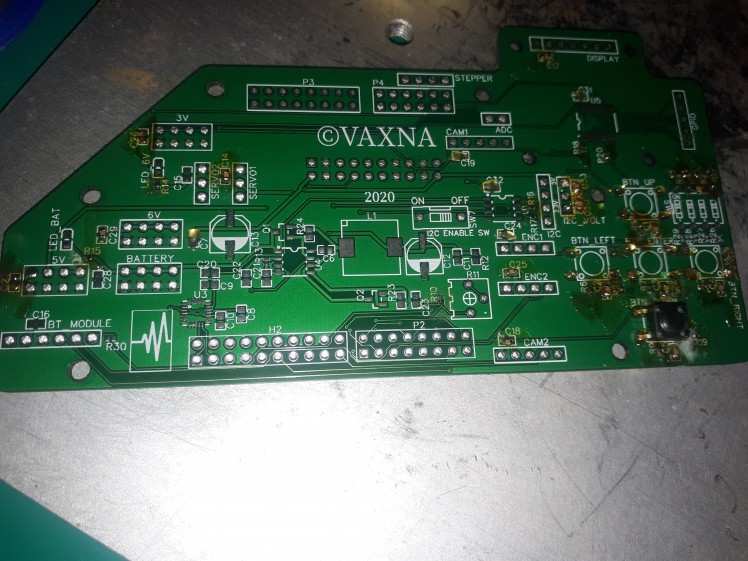
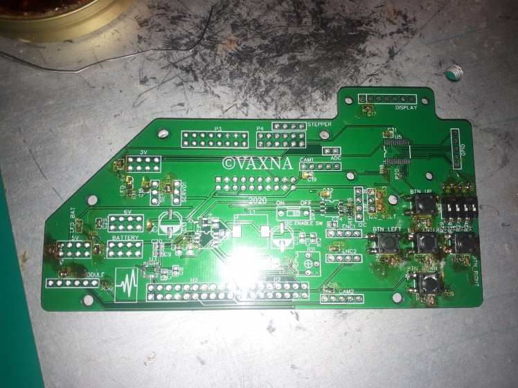
The PCB was designed with layout that will fit on existing motor board and other parts such SD1306 display and K64F controller.
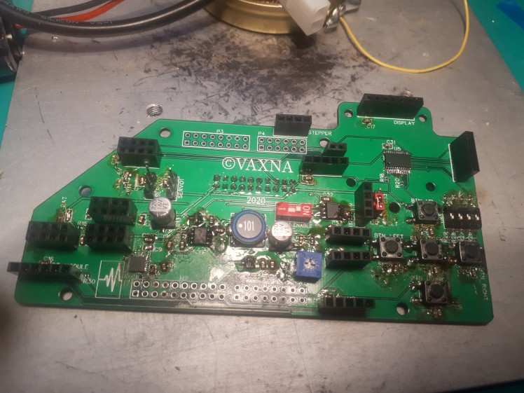
And here it is, 5 new pieces which freshly arrieved form China:
The cruel reality
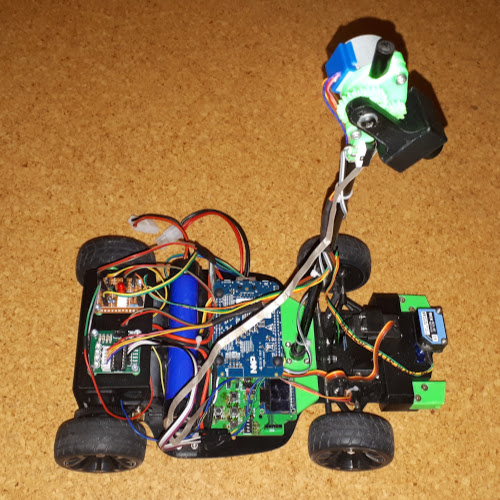
Sadly we had ordered our board with components too late. When we were ready to solder them, the schools got locked because of COVID-19 and I don't have correct equipment for SMD soldering at my home. So for temporary solution I took a lot of wires and tape and somehow put everything together. You can look at my result yourself.
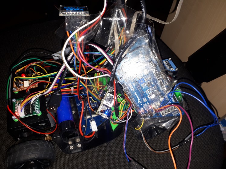
But this state should be enough for testing. We got motors, servos, stepper, encoder and K64F working, but it would be nice to have everything in more stable form. Right now there are sometimes problems with connections, so servos are sometime randomly moving and unexcepted stuff happens. Also we are missing some features, such a gyroscope and and buttons.
Fighting with cruel reality
I have waited some time if schools will finally open and I will be able to continue my work. But it seems like the will be closed for some more time. So I decided to go to my school, pick parts which I kept there in my locker and decided to try to solder it all at my own. I don't have air soldering station, liquid flux nor tweezers. But I managed to solder all the parts and mostly check if they are working.
This is image from beggining of soldering. But there is already a lot of work finnished. You can probably at first sight just see the button, but if you look in more detail, you will be able to see some capacitors soldered and if you look even into more detail, then you will be able to see resistors. They look like just tiny black dot as they are of size 0402 (0.4x0.2mm).
Also you are able to see big yellow drops without component on board. This is my solution to the missing liquid flux. Before I solder any component I heat my soldering iron to 200°. This temperature is ideal, because it makes flux liquid, but it doesn't make it vaporize or smoke. First thing I do is that I insert my soldering iron into the solid flux and then move it above the board. At this moment there should be enough amount of flux on the tip. Then I touch board with the tip and the flux transfers to the board.
This process with adding flux is necesary, because if you try to get the flux at soldering temperatures (I use 350°), then the flux doesn't stay at the tip and thus is unable to get onto the board and component.
After the flux is on all spots you want to solder currently components on, then you can turn soldering iron to the soldering temperatures. Wait till the soldering iron is heated and place component on the board. If you are soldering capacitors or resistors, then place component right next to flux, then place tip of the soldering iron to the side of component in way that it touches by biggest possible are and push that component against flux. This will transfer heat trough the component to the flux, so it will melt and component will be inside it. After very short time the flux will activate and clear board and component pads. Still hold soldering iron that way and touch both component pads with a tin. After this there should be your component with melted tin on it's spot, then you should remove soldering iron.
This requires a bit of practice as components stick to the soldering iron or they rotate on the pads or even stand up (they rotate by 90 degrees, the way that they point up and stand on single pad). This is usually caused by having tin only on one of pads. Also you should keep in mind that pads connected to the ground plane are able to suck huge amount of heat. So you should heat them longer time even like 10 seconds, so component properly stick. You should be able to see small change of tin ball as it sticks correctly to the ground plane (this change is really fast and take like half second).
If you are able to use liquid flux or air soldering station, then for sure use it. It is a lot easier than this way.
Here I have soldered all buttons and switch and also most of the capacitors and resistors.
I will now explain why I soldered bigger components like switches and buttons before smaller ones, even if it is better practice to solder small components first.
The reason is very simple. I want my board tested as well as possible and be working on first try. I am mainly soldering those components before I solder I/O expander because it will make testing harder. I test those components by touching the correct pad on I/O expander, which belongs to tested button or switch and by other onto the 3.3V or ground. When second pad is ground, then there should be resistivity of 10kΩ. If the resistivity is zero, then you have short circuited grounding resistor, if the resistivity is infinite, then you have bad connection of some part. When second pad is 3.3V, then the resistivity should be infinite, but when you press the button it should change to 1kΩ. If this doesn't happen then you have again some issue in your circuit. Switches are tested the same way as buttons are.
Also you should be checking all those capacitors. Most of them are on some power rail. There are four power rails called battery, 6V, 5V and 3.3V. When you solder capacitor, then check to what rail it belongs and measure capacity there. It should increase by the size of capacitor soldered. Mostly all capacitors are 100nF, so it should increase by this. If this is the first capacitor soldered onto the rail, then the capacity should be 100nF. After you measure the capacity of rail you should get correct value. If the multimeter is unable to measure capacity, then it means you got short circuit. If it measures unchanged capacity, then it means that there is bad connection between capacitor and board.
Also I recommend to solder capacitors before resistors or any other components onto rails as you then won't be able to measure it's capacity after it. When you are measuring resistors, then you should find two correct pads where they connect and check if there is short circuit or bad connection.
Fighting with cruel reality second time
Right now I can just tell you: Apply as small amount of tin to small components with a lot of legs as possible.
If you will take a lot of tin and put it onto legs, then they would all connect together and you will have a huge problem with removing it. When you try to solder component like this, then take as much small amount of tin possible and try to solder it. If the amount won't be enough then add the tin slowly. When I soldered it, I thought I am adding just ideal amount, but it was way toooo much. Second issue was that I tried to remove tin for long time, till some of pads deatached from board. I can just again say that if this happens to you then oldschool tin extractor works just fine and try to finnish your removing as soon as possible.
I will also give few words how I was fixing those pins disconnected from board. I found that best tool for inspecting is strong lamp and you should place PCB in front of the lamp and it shines through, so you will be nicely able to see connected traces or missing ones. I was lucky and all traces were still connected, they just moved from their original position and touched other pads. Most simple way to fix this is to heat your soldering iron to bit higher temperature and move the tracks, so they don't touch each other or even take them up from board and place them on leg of component.
And I lied a bit. One trace got disconnected from board. It was trace from I/O expander's interrupt pin. I was planning to fix it by connecting wire from interrupt pin to the correct place on board, but I decided to not fix this pin and keep it disconnected as I don't need interrupts from this IC for anything yet. But it might be important to fix it in future if I decide to connect something to GPIO header what would need iterrupts.
You can see result below after soldering almost all components:
There are only missing headers for connecting K64F as it is the last thing I need to do and also it is tallest component. But before I solder it, I connect this board to the motor board through the connector on bottom. This allow me to check if battery and 6V rails are working. It is detected really fast as two blue LEDs should light up. Probably everything is working if the LEDs are lighting and no components blew up. Also it is now good time to take screwdriver and multimeter. Connect multimeter to the 6V rail and measure voltage. It will be probably a bit off from 6V. Now take screwdriver and slowly turn with blue potentiomerter on the board till you set the voltage of 6V rail to 6V.
Now solder those remaining headers and connect K64F. Now it is time to hope that everything is soldered correctly and you can test it out. Upload some program for display and see if it lights up, then servos, camera, etc. I hope it will all work for you. For me it luckily all worked on first try.
Does it works?
As you can see, we had built our own track and our car is moving! It's not yet totally perfect, but it works and we will still work on our car till competition will come, to win it.
Future plans
It is possible we are also going to use ultrasonic sensor together with laser one to get even more precise results when searching for cube on track. Also we need to finish our code to make our car run properly, but we got a lot of time for that as COVID-19 delayed the competition and there isn't yet new date for it.
How to make own testing track
If you are interested in making your own track like I did, you would need huge roll of paper. I don't know exactly the size, but you can see it is huge. You have to place 3 those huge papers together and use transparent tape, so it will hold to ground. The you should draw with pencil shape of your track, as it is really easy to fix this if you make wrong draw. After you are sure you had designed your track correctly, then use black electric tape to make all those edges.
Results
Except our results here soon.
Schematics, diagrams and documents
CAD, enclosures and custom parts
Code
Credits
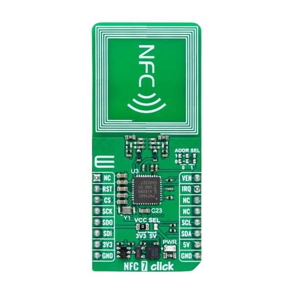
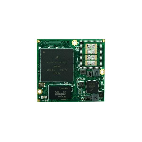
Related products


Leave your feedback...