
Nrf5340 Oscilloscope Band

Made by aniketdhole / 3D Printing / Displays / Environmental Sensing / Productivity / Wearables
About the project
Measure and Analyse Voltages on the Go with nRF5340
Project info
Difficulty: Moderate
Platforms: Adafruit, Ender, Nordic Semiconductor
Estimated time: 2 days
License: Apache License 2.0 (Apache-2.0)
Items used in this project
Hardware components

Software apps and online services
Story
Almost all Hobbyist and Makers dream about owning a Oscilloscope but due to huge prices we could not afford it. So why not make your own?
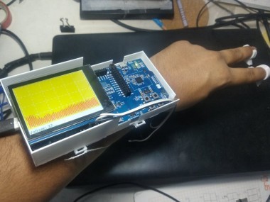
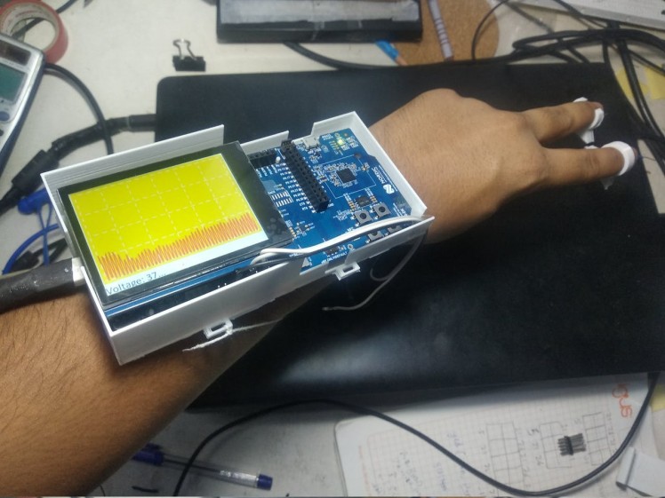
I have created a Hand Held Oscilloscope which can be used as a wearable to measure voltages with probes attached to your fingers.
1 / 2
It uses nRF5340's inbuilt ADC to read Voltage. ADC means Analog to Digital Converter. It measures the analog voltage signal and converts it into Digital Bits in range of 0 to 1023.
ADC

ADC
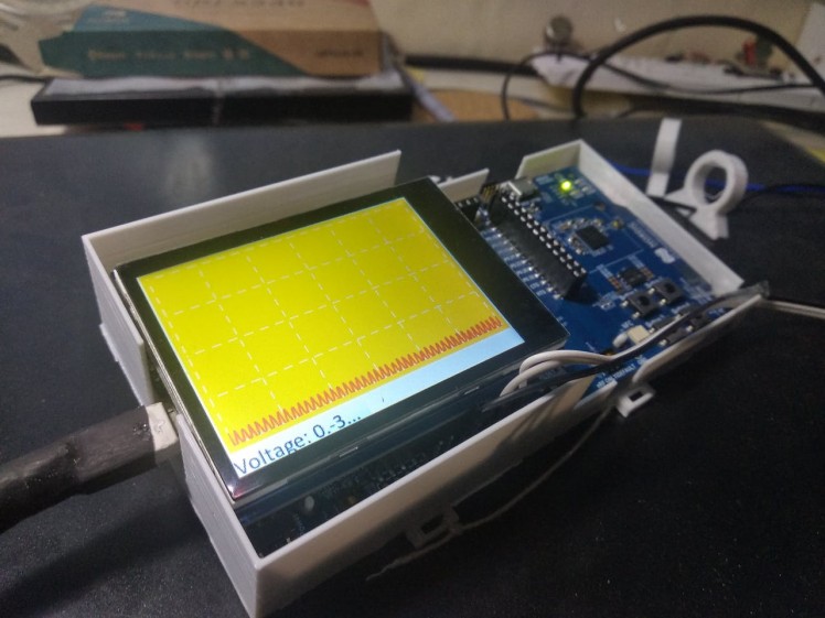
It then uses LVGL Display Library from Zephyr OS to plot that data on the Adafruit Display using Charts.
Adafruit TFT Dislpay

Adafruit TFT Dislpay
How I Made It:Software:
- First I had setup the nRF5340 with Zephyr OS and all its dependencies like west.
- Then Installed the nRF Toolchain.
- Then tested out sample code for blinky and ncs-display.
- Then worked on reading values from Potentiometer and PWM Signals generated from Arduino

Hardwareand Build
The Main Parts were the Body Case and Wiring the Cables
- The Body was 3D Printed and Sketched by me using Fusion360, Here is the STL Files
1 / 2 • 3D Printed

3D Printed
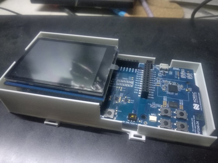
- Then the Jumper Cables were Attached to nRF5340 by soldering Headers to Remaining Analog and Ground Pins as All header pins were occupied by Display Shield.
- To use it as a Wearable, I have added place for adding Flaps on both sides of 3D Printed Case
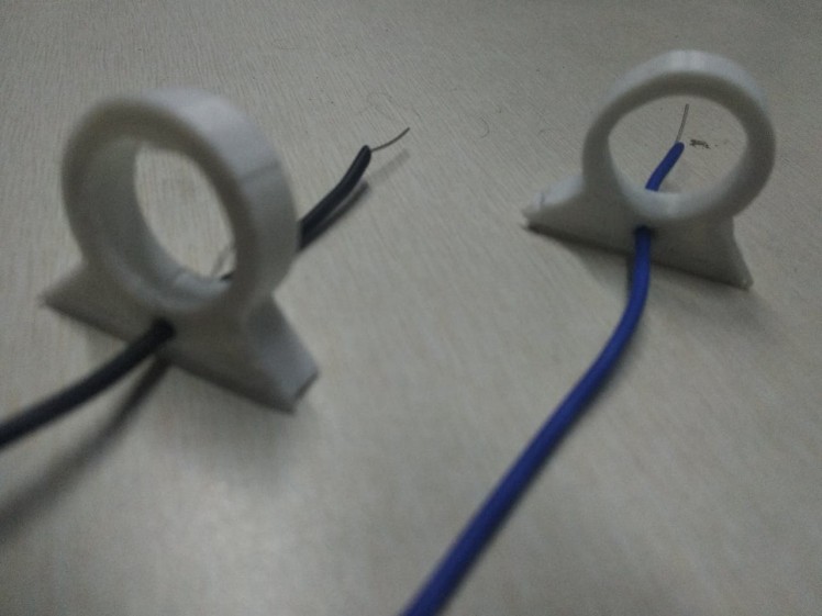
- And to use with Fingers I have Printed Finger Holders
There are many improvements I am adding to it
- Adding Voltage StepDown Circuit to support greater voltages
- Adding Current Sensing by using Shunt Resistor Method
- Creating a GUI with touch for switching between features and voltages.
Schematics, diagrams and documents
CAD, enclosures and custom parts
Code
Credits
Related products


Leave your feedback...