
Nox - A House Wandering Robot (ros)

Made by electrouser1021 / Robotics
About the project
Nox is a nice (and time-consuming) robot which uses SLAM (ROS) with a Kinect to navigate in its environment.
Project info
Difficulty: Difficult
Platforms: Adafruit, Arduino, Raspberry Pi, ROS
Estimated time: 4 months
License: GNU General Public License, version 3 or later (GPL3+)
Items used in this project
Hardware components


Story
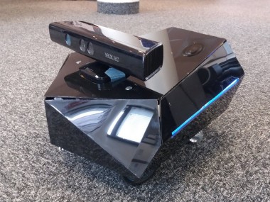
Nox is a differential-drive robot built using ROS, Raspberry Pi and Arduino. I started the project as a robot base with basic navigation I could then use for other things, like a vacuum cleaner. However I quickly decided to make it a standalone robot with a proper design, as it's often missing in DIY robots. In its current state the robot can use SLAM (gmapping) to create a map of its surroundings (using the Kinect depth perception to detect wall and obstacles) and localize itself within the map. It can plan a path to a given goal and drive to it avoiding obstacles.
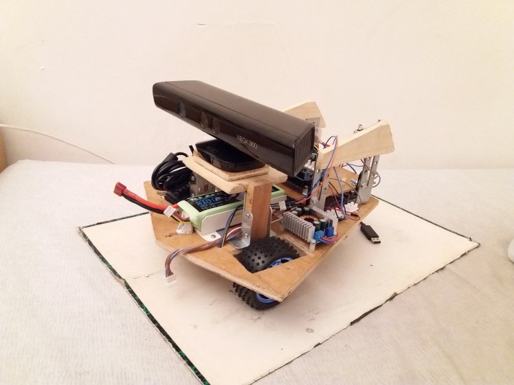
RViz viewNox is powered by a 11.1v Lithium-Ion battery and driven by two motors. The front panel can be removed to change the battery. A slotted hole and a screw fasten it and allow to put batteries of different lengths. I put a battery alarm with a screen to monitor the level.
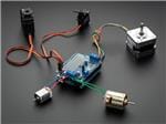
The motors are two 12v DC motors (107rpm) from Banggood. They are nice but I actually don't need the robot to go that fast and I would have been okay to trade some of the speed for more accurate encoders.
About the design, the main constrain was to have something that integrates well with the Kinect, as I was building the robot around it. I was inspired by the triangular look of a lot of modern style objects (and a lot by Deus Ex I have to admit). I really wanted to have a nice and professional looking robot as it's something that's often missing in DIY robots (but don't worry the wiring is as messy as it should be). Spending a few weeks on the CAD model to tweak everything was necessary.
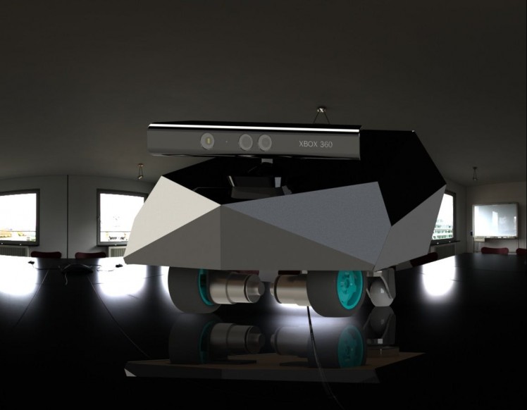 3D rendering
The lights on the side are recycled from a New Year's Eve glowing stick I got for free and serve to indicate the robot states. When the Arduino is not connected to the ROS master (indicating that the robot program has not started yet) the lights blink three times in a row very quickly. When driving, the lights have a more "breathing"-looking blink and the blinking speed depends on the robot speed.
Not connect blinking Idle blinkingStructure
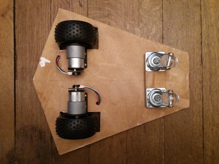
As stated above, the robot is a differential drive one, so the motor are placed on the same axis. The base is made of wood with two caster wheels for support. I initially planned on using one caster wheel to avoid the hyperstatic thing but couldn't find a good-sized one. The rest of the structure is made mainly of wood and metal brackets, easy to find in any DIY retail store. On the rear part of the robot plates can be stacked to put the electronic boards on.
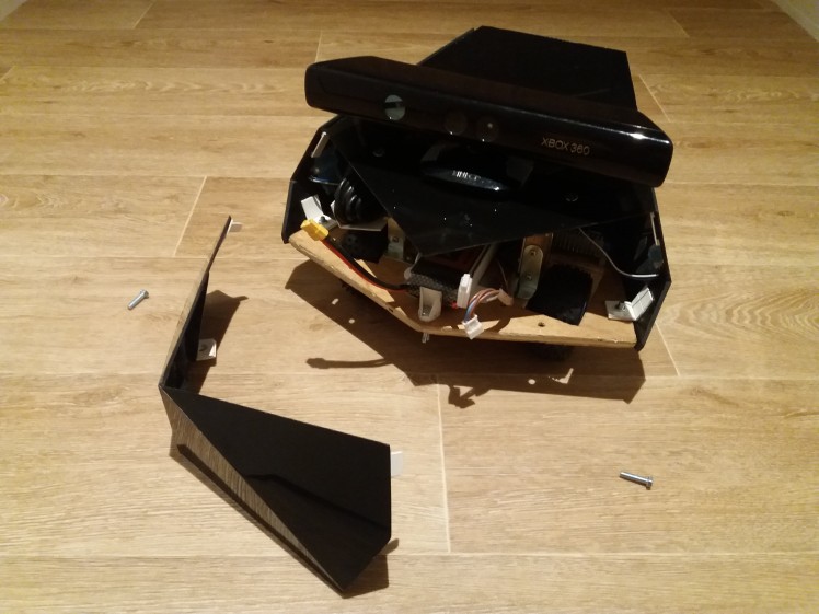
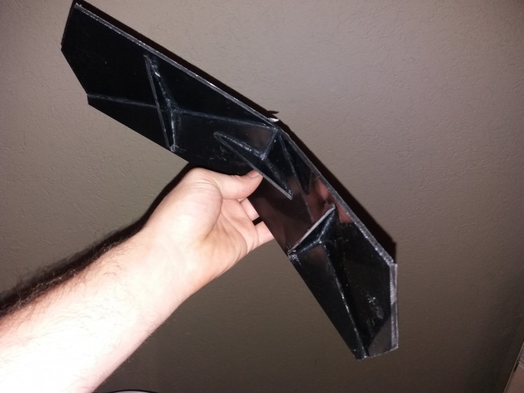
The carter is made of black plastic plate, cut and glued by hand (will definitely use 3D printing next time).
Hardware
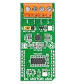
On the inside the main controller is a Raspberry Pi 3B running Ubuntu and ROS. The Raspberry can be accessed from a outside computer through WiFi and ssh to give order to the robot. The ROS program carries out odometry calculation, navigation planning, and mapping using the Kinect. The Raspberry Pi sends the velocity command to an Arduino which controls the two motors with a PID through an Adafruit Motor Shield. It reads the value of the encoder, calculate the speed of each motor and send back the value to the Raspberry for odometry calculation. Arduino and Raspberry Pi are connected by USB and the Arduino program acts as a ROS node (look for rosserial for more info).
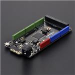
I used different types of Arduino before settling down for the good one. At first I used the basic Arduino Uno but I didn't have enough interrupt pins to read the encoder values with (the best method to do so with Arduino). The speed and accuracy were limited as I had to resort to other programing tricks to make it work. I tried using an Arduino Leonardo but the limiting factor was memory and I had to finally switch to an Arduino Mega 2560. A blessing in disguise as I have plenty of memory and pins left to add new functions now.
Kinect 360 was part of the project from the start, as I wanted to do SLAM (Simultaneous Localization And Mapping) but without spending a ton of money on a lidar. A kinect is basically a 25€ 3D-camera (of course don't expect the same accuracy as an Hokuyo) and, in addition to the depth scanning needed for SLAM, can be also used for computer vision, has an accelerometer and a microphone array. All of which being handy for the following steps of the project.
Two DC converters are used to convert the voltage. The motor are running directly with the battery voltage (more or less 11.1v). The command part (including Raspberry Pi, Arduino and encoders) is running on 5V converted from the battery. The Kinect needs a 12v stabilized voltage and a converter provides it from the battery too.
Software
On the software part, I used ROS Kinetic. The only node I really wrote is the "nox_controller" which, as his name doesn't really imply, is used to compute the odometry from the Arduino >On Differential Drive Robot Odometry with Application to Path Planning" (I actually did my own formulas but they are the same, anyway the paper is worth a read). Covariance matrices are given in the odometry but not currently used (however it will become useful if I'm integrating a IMU to the odometry).
In the Arduino the motor control is done through PWM. A PID is supposed to manage each motor speed but as the PWM/motor speed ratio is very linear I got good result with a direct command of the speed and desactivated the PID for now. Don't worry though correct PID implementation and calibration is on its way.
Mapping and Path Planning
The algorithm used for SLAM is gmapping. A nice implementation already exists on ROS and I used it. I plan to try RGB-D SLAM in the near future.
Concerning the path planning, I tried different local planners available on ROS and settled with DWA local planner, as it gives the best result for differential drive robots. I still have a lot of tweaking to do as Nox can sometimes got stuck getting to close to a door or some obstacles. Moreover after some time navigating and especially if the robot is changing rooms, the map starts to get messy and the robot got lost. I mainly blame the quality of the kinect (also the shaking of it) and the odometry for that. Fusing the odometry from the encoder with an IMU could be a next step in solving this issue.
In order to get the best odometry as I could, I did some calibration. I basically drove the robot in a straight line, measured the distance from the starting point manually and compared it with the odometry distance. With the difference between the two I computed a scale to correct the odometry measure. I did the same thing for the rotation by rotating the robot on its own and comparing the odometry with the reality. You can check ROS navigation tuning guide and the paper it's partially based one here for more information.
Next steps in the project:
- Totally independent on-board navigation (currently still relies for some part on an outside computer) with random goal spawning or exploring behavior.
- Fusing the odometry with an IMU (ROS proposes nice implementations of Kalman filters) to improve the accuracy
- Use OpenCV to add some computer vision features
- Implement voice recognition (I was thinking about using HARK-ROS but if anyone as a suggestion, I'm open to it)
I would like to thank and give credit to the following:
- Sungjik's project which was the biggest inspiration to make my own robot
- "ROS Navigation Tuning Guide" by Kaiyu Zheng
- "How to connect Kinect to Raspberry Pi 2 or 3 with ROS" Youtube video by Robotics Weekends
- "Communication between Raspberry Pi and PC (ROS)" by mktk1117
- "On Differential Drive Robot Odometry with Application to Path Planning" by Evangelos Papadopoulos and Michael Misailidis
- Prof. Shuro Nakajima from Wakayama University where I got the occasion to learn by working on the PMV (Personal Mobility Vehicle) project (check it it's awesome)
- Everyone in the ROS community that got the same problems as me and the ones who answered them
Schematics, diagrams and documents
CAD, enclosures and custom parts
Code
Credits
Related products


Leave your feedback...