
Netduino Environmental Sensor Project

Made by Jade7272 / Environmental Sensing
About the project
Sensing, power, air quality, temperature, humidity, and air pressure displayed on an LCD and transmitted by MQTT.
Items used in this project
Hardware components


Story
The Story
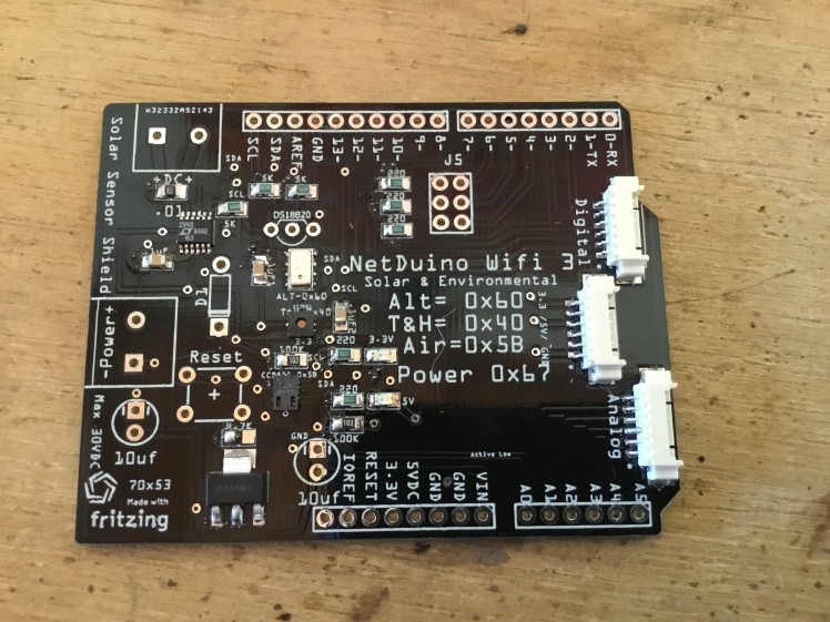
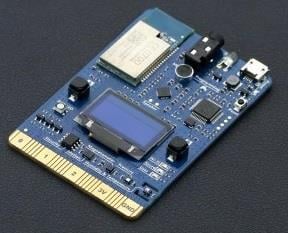
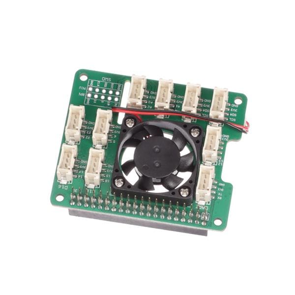
As we become more environmentally aware of our surroundings we require more information about it. This shield which plugs right onto the Netduino with Arduino compatible pins is capable of sensing a whole bunch of environmental variables including a Digital Gas sensor which measures CO2 and VOC's an Altimeter which measures Barometric Pressure and Altitude, a one wire Temperature Sensor DS18B20 (Non I2C), a Temperature Humidity Sensor and last but not least a Voltage Current sensor which is capable of sensing Input power or using a clip on Current meter you can sense your house power usage..All this on one small board with a micro LCD to see what's happening real time or go on line and watch your house while your away.
This project consists of multiple parts:
1. Sensors and Board Design
2. Soldering Up Your Board
3 Programming Your Netduino WiFi 3
4. Box Design and Build
1. Sensors and Board Design
I DESIGNED THIS BOARD SO IT IS COMPATABLE WITH THE NETDUINO WIFI
If is editable with Fritizing www.fritzing.com, I will include the Fritzing file for editing and your enjoyment..
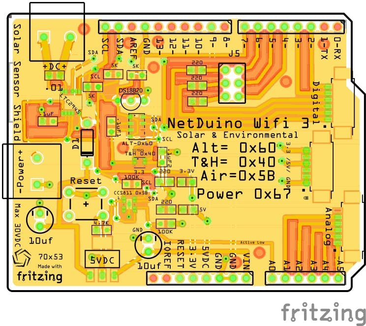 Fritizing Design
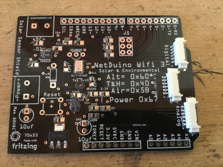
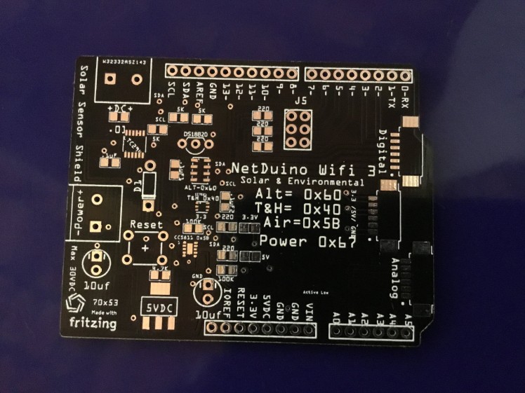 Printed PCB From PCBway.com
The Board's Sensors
CCS811
The CCS811 is an ultra-low power digital gas sensor solution which integrates a metal oxide (MOX) gas sensor to detect a wide range of Volatile Organic Compounds (VOCs) for indoor air quality monitoring with a microcontroller unit (MCU), which includes an Analog-to-Digital converter (ADC), and an I²C interface. CCS811 is based on ams unique micro-hotplate technology which enables a highly reliable solution for gas sensors, very fast cycle times and a significant reduction in average power consumption. The integrated MCU manages the sensor driver modes and measurements. The I²C digital interface significantly simplifies the hardware and software design, enabling a faster time to market. CCS811 supports intelligent algorithms to process raw sensor measurements to output a TVOC value or equivalent CO2 (eCO2) levels, where the main cause of VOCs is from humans. CCS811 supports multiple measurement modes that have been optimized for low-power consumption during an active sensor measurement and idle mode extending battery life in portable applications. CCS811 is available in a 10 lead 2.7mm x 4.0mm x 1.1mm, 0.6mm pitch LGA package.
DS18B20
https://www.mouser.mx/datasheet/2/256/DS18B20-370043.pdf
The DS18B20 digital thermometer provides 9-bit to 12-bit Celsius temperature measurements and has an alarm function with nonvolatile user-programmable upper and lower trigger points. The DS18B20 communicates over a 1-Wire bus that by definition requires only one data line (and ground) for communication with a central microprocessor. In addition, the DS18B20 can derive power directly from the data line (“parasite power”), eliminating the need for an external power supply. Each DS18B20 has a unique 64-bit serial code, which allows multiple DS18B20s to function on the same 1-Wire bus. Thus, it is simple to use one microprocessor to control many DS18B20s distributed over a large area. Applications that can benefit from this feature include HVAC environmental controls, temperature monitoring systems inside buildings, equipment, or machinery, and process monitoring and control systems.
Si7021 I2C
https://www.mouser.mx/datasheet/2/368/Si7021-A20-707879.pdf
The Si7021 I2C Humidity and Temperature Sensor is a monolithic CMOS IC integrating humidity and temperature sensor elements, an analog-to-digital converter, signal processing, calibration data, and an I2C Interface. The patented use of industry-standard, low-K polymeric dielectrics for sensing humidity enables the construction of low-power, monolithic CMOS Sensor ICs with low drift and hysteresis, and excellent long term stability. The humidity and temperature sensors are factory-calibrated and the calibration data is stored in the on-chip non-volatile memory. This ensures that the sensors are fully interchangeable, with no recalibration or software changes required. The Si7021 is available in a 3x3 mm DFN package and is reflow solderable. It can be used as a hardware- and software-compatible drop-in upgrade for existing RH/ temperature sensors in 3x3 mm DFN-6 packages, featuring precision sensing over a wider range and lower power consumption. The optional factory-installed cover offers a low profile, convenient means of protecting the sensor during assembly (e.g., reflow soldering) and throughout the life of the product, excluding liquids (hydrophobic/oleophobic) and particulates. The Si7021 offers an accurate, low-power, factory-calibrated digital solution ideal for measuring humidity, dew-point, and temperature, in applications ranging from HVAC/R and asset tracking to industrial and consumer platforms.
LTC®2945
The LTC®2945 is a rail-to-rail system monitor that measures current, voltage, and power. It features an operating range of 2.7V to 80V and includes a shunt regulator for supplies above 80V to allow flexibility in the selection of input supply. The current measurement range of 0V to 80V is independent of the input supply. An onboard 0.75% accurate 12-bit ADC measures load current, input voltage and an auxiliary external voltage. A 24-bit power value is generated by digitally multiplying the measured 12-bit load current and input voltage data. Minimum and maximum values are stored and an overrange alert with programmable thresholds minimizes the need for software polling. Data is reported via a standard I2C interface. Shutdown mode reduces power consumption to 20µA. The LTC2945 I2C interface includes separate data input and output pins for use with standard or opto-isolated I2C connections. The LTC2945-1 has an inverted data output for use with inverting opto-isolator configurations.
MPL3115A2
The MPL3115A2 is a compact, piezoresistive, absolute pressure sensor with an I2C digital interface. MPL3115A2 has a wide operating range of 20 kPa to 110 kPa, a range that covers all surface elevations on earth. The MEMS is temperature compensated utilizing an on-chip temperature sensor. The pressure and temperature data is fed into a high resolution ADC to provide fully compensated and digitized outputs for pressure in Pascals and temperature in °C. The compensated pressure output can then be converted to altitude, utilizing the formula stated in Section 9.1.3 "Pressure/altitude" provided in meters.The internal processing in MPL3115A2 removes compensation and unit conversion load from the system MCU, simplifying system design. MPL3115A2's advanced ASIC has multiple user programmable modes such as power saving, interrupt and autonomous data acquisition modes, including programmed acquisition cycle timing, and poll-only modes. Typical active supply current is 40 μA per measurement-second for a stable 10 cm output resolution.
Bill of Materials and Where to Buy
you can purchase the needed materials from either mouser.com or digkey.com the Bill of Materials is below
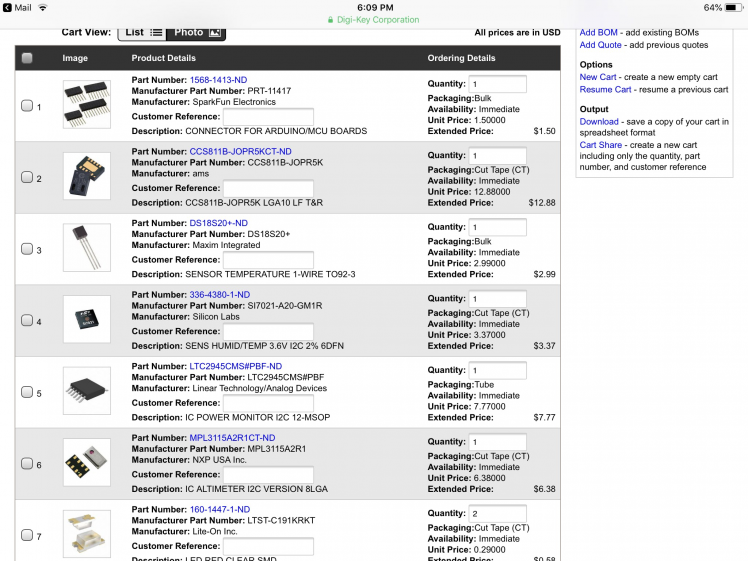 1 / 3 • Digikey shopping Cart
********NOTE ****** Please pay attention to what voltage regulator you are buying ..see below
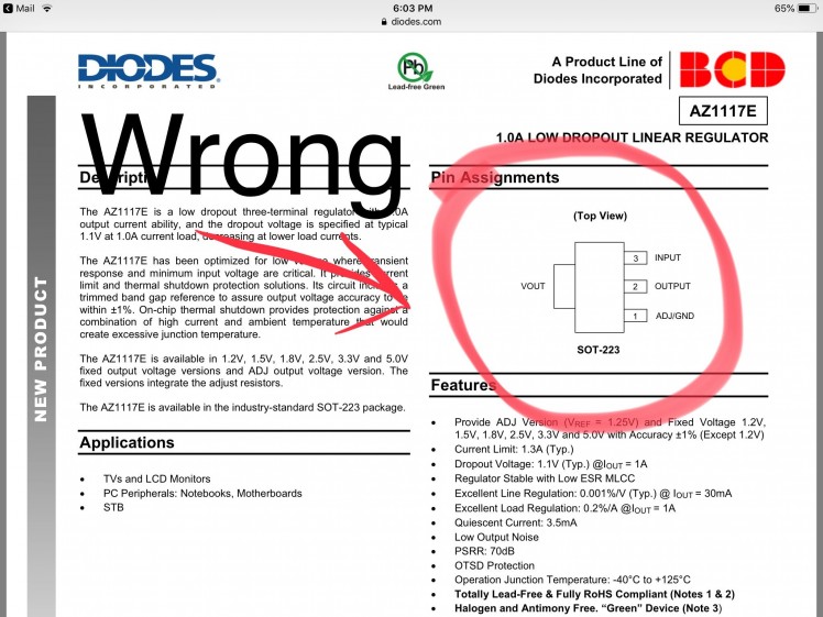 1 / 2 • Please note
2. Soldering up your board
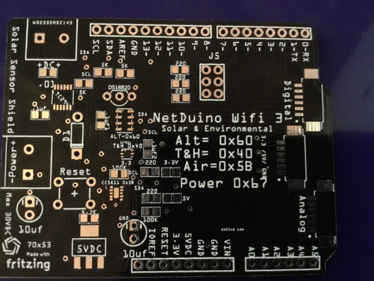 The PCB
 Apply the Solder Paste Sparingly
Note: I only put solder paste on one side of the resistors and capacitors as it’s easier to solder them on.
 Ready for oven
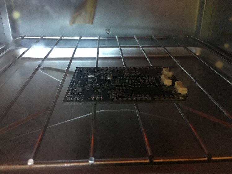 Preheat
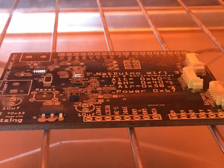 Notice reflow solder spreading out
 When you see Solder shrink and turn silver wait 20 seconds and remove from oven carefully
 Cleaned up and ready for soldering other side of small pieces
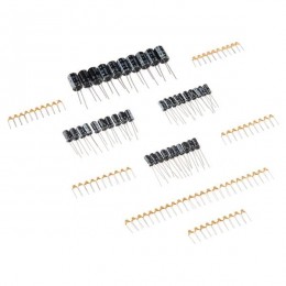
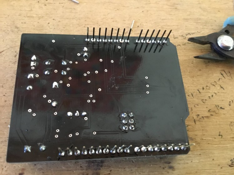
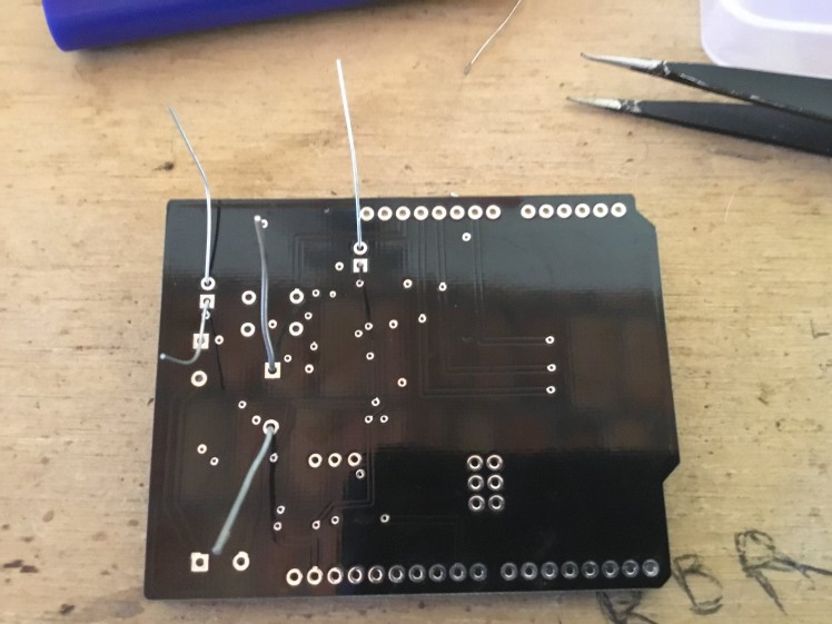 Now solder the through hole pieces
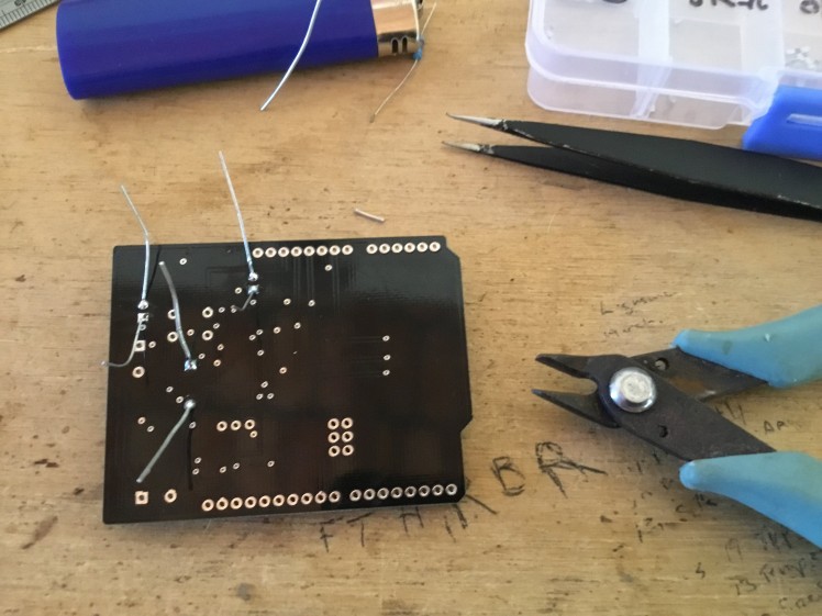 Flush cut side cutters a necessity
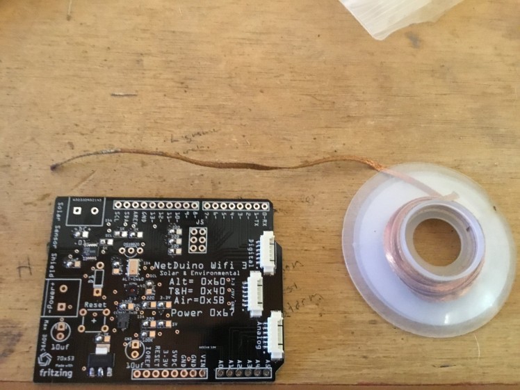
 Solder the DS181 temp sensor
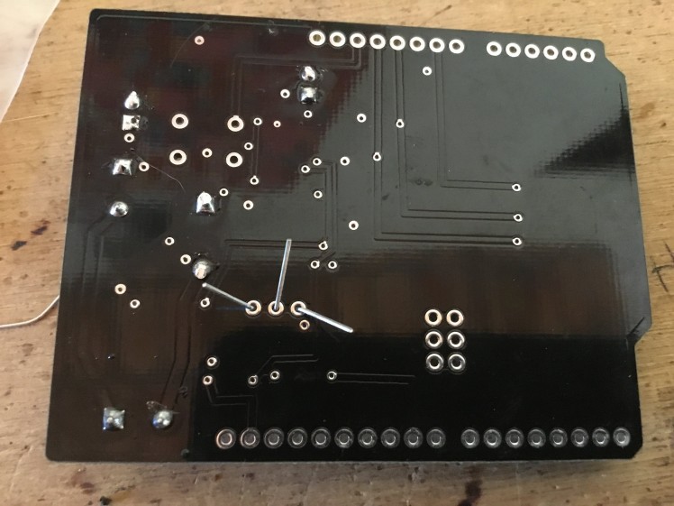
 1 / 2 • Soldered
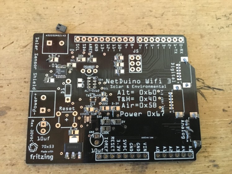
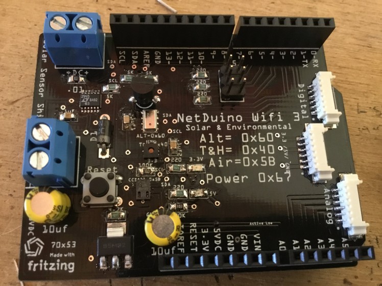 Complete and ready for Testing
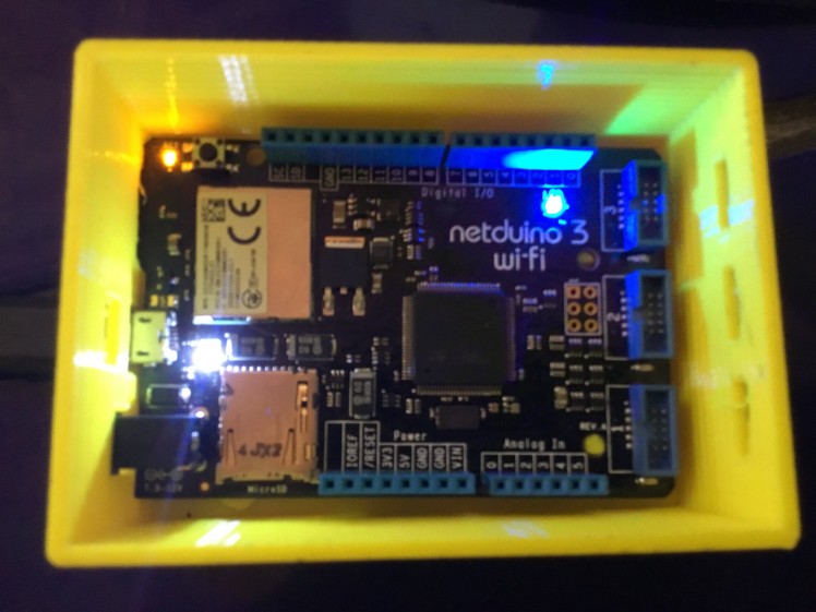
Plugged into the Netduino
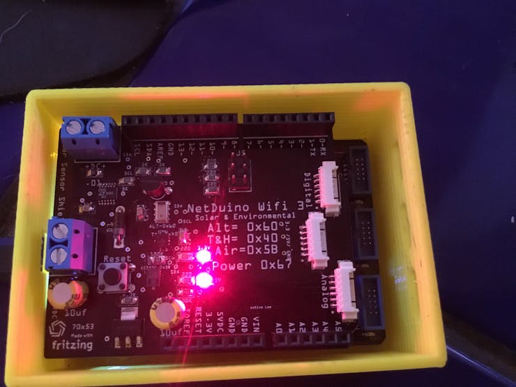 Powered up
3. Programming Your Netduino WiFi 3
Note at the time of submitting there was some missing sketch documentation for 1/2 of my I2C sensors and the Adafruit LCD display. But I will endeavour to persevere and program as much as I can and provide the necessary instructions ..I am new to C# so this will be interesting ...
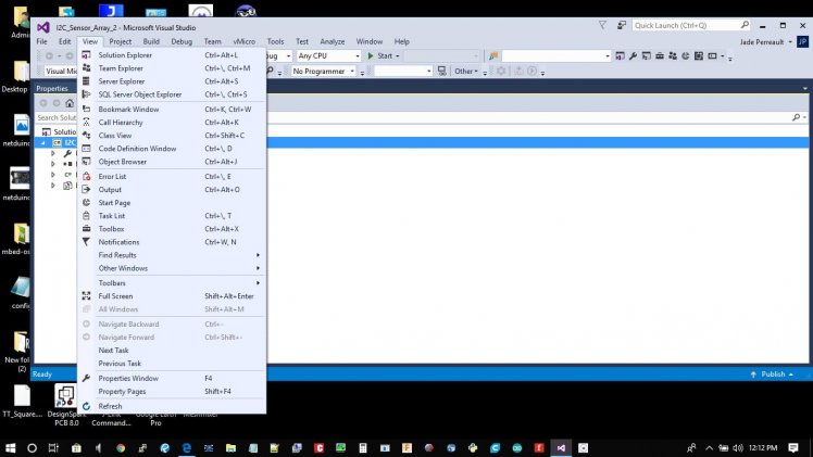
The first step is to Download and install Microsoft visual studio 2015 not 2017 follow the getting started steps And download the necessary programs..
Open Visual Studio and Make a new Project ..
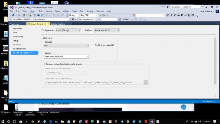
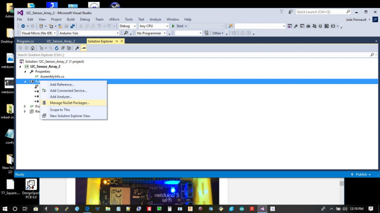
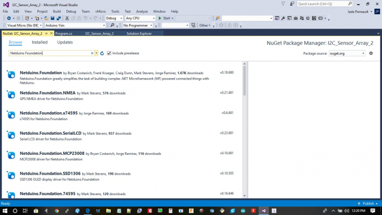
This was the Part that I was missing in all of my 200 attempts at this program you need to add the NuGet Packages that you are going to use in your sketch here..
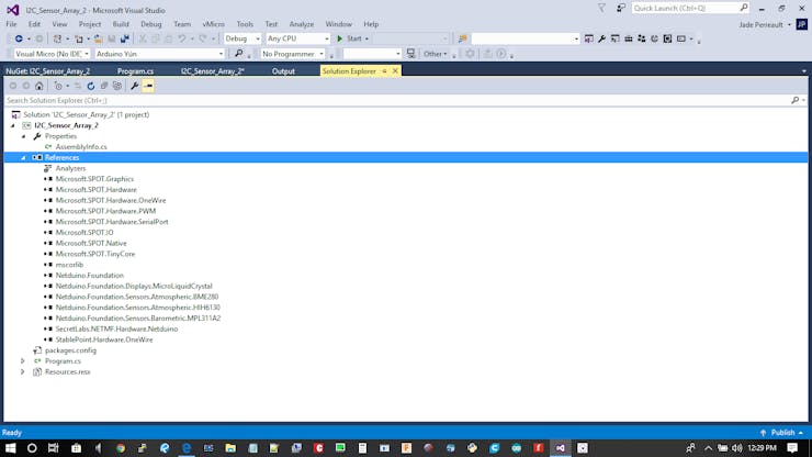
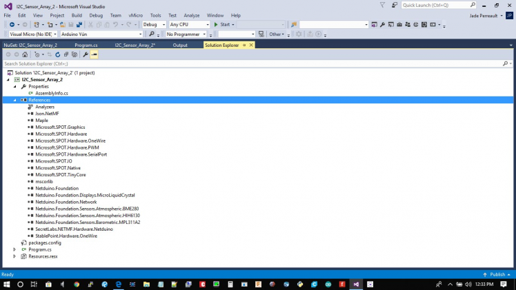 All the installed dependancies of the project
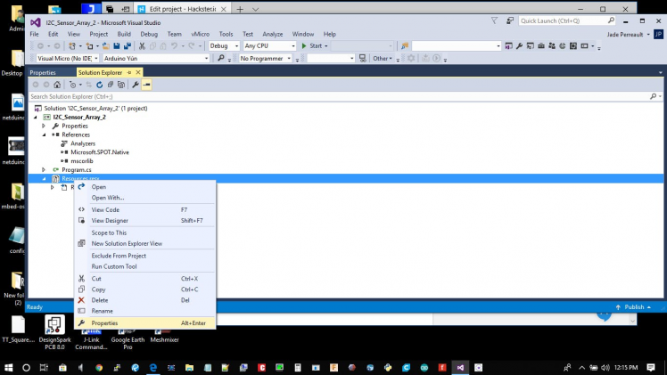
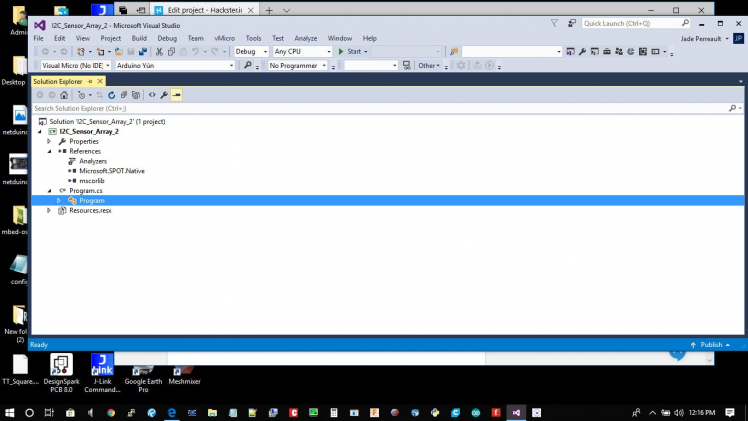
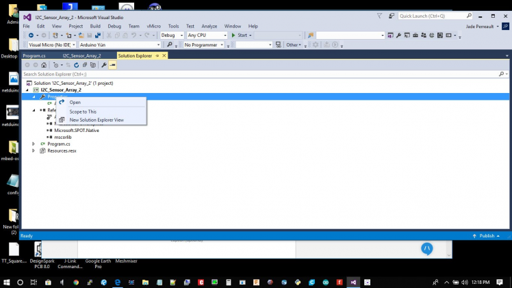
Next is the Programing double click on the program.cs
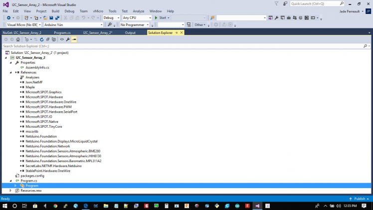
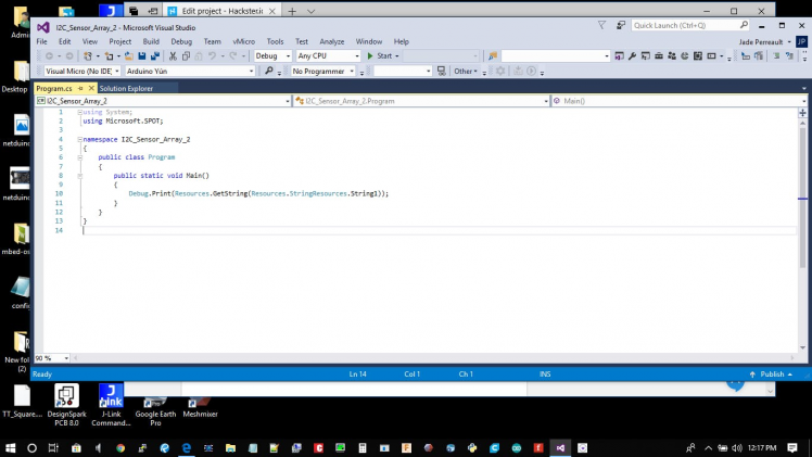
It'll open this screen
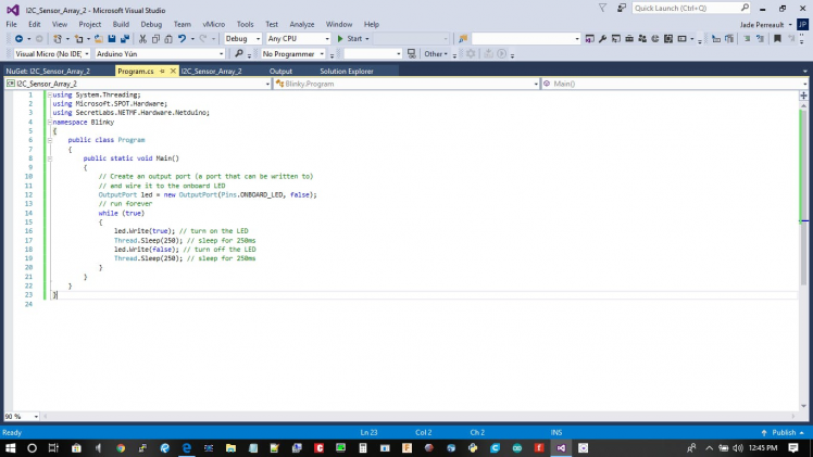
I Pasted Blinky into the sketch and uploaded it to test the connection and it'll be the start of the program
using System.Threading;
using Microsoft.SPOT.Hardware;
using SecretLabs.NETMF.Hardware.Netduino;
namespace Blinky{
public class Program   {
public static void Main() {
// Create an output port (a port that can be written to)
// and wire it to the onboard LED
OutputPort led = new OutputPort(Pins.ONBOARD_LED, false);
// run forever
while (true)
 {
led.Write(true); // turn on the LED
Thread.Sleep(250); // sleep for 250ms
led.Write(false); // turn off the LED
 Thread.Sleep(250); // sleep for 250ms
  }
}
 }
}
After you hit Run this is what your output in the Debug window should look like … If it doesn't fix the errors and try again :)
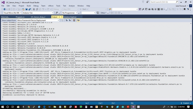 Building and sending program to the Netduino
Reboot your Netduino
http://netduino.foundation/Library/Sensors/Barometric/MPL3115A2/
The Altimeter Code to be Integrated
using System.Threading;
using Microsoft.SPOT;
using Netduino.Foundation.Sensors.Barometric;

namespace MPL3115A2Test
{
public class Program
{
public static void Main()
{
Debug.Print("MPL3115A2 Polling Example");
 var mpl3115a2 = new MPL3115A2(updateInterval: 0);
 while (true) { mpl3115a2.Update();
Debug.Print("Temperature: " + mpl3115a2.Temperature.ToString("f2") + ", Pressure: " + mpl3115a2.Pressure.ToString("f2")); Thread.Sleep(1000);
 }
}
}
}
4. Box Design and Build
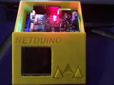
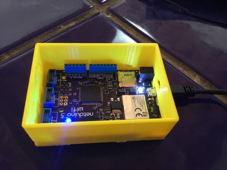 Nice compact box
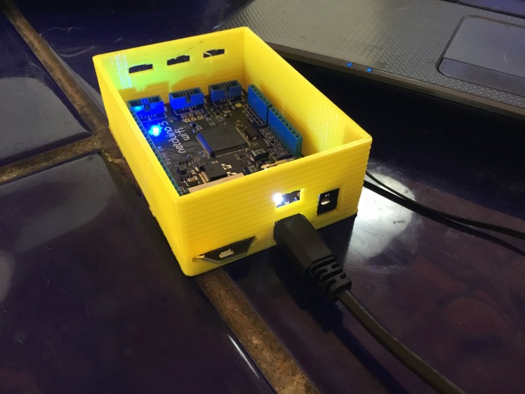 Front port for Power in If wanted
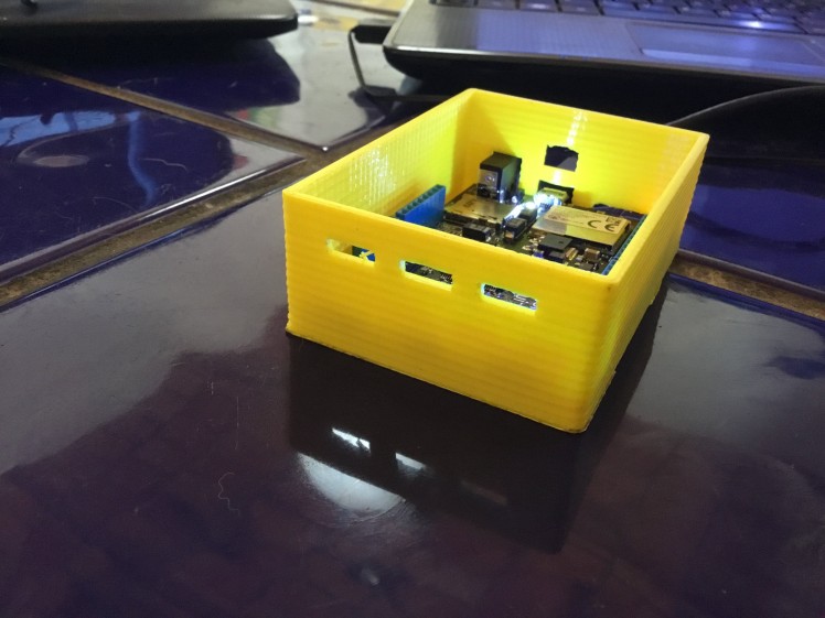 Rear ports for added sensors
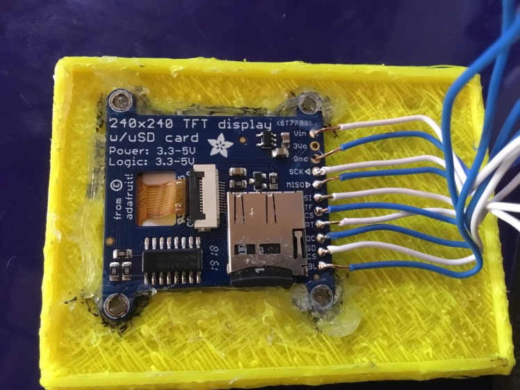
The Display Can be Purchassed here https://www.adafruit.com/product/3787

I soldered wires instead of headers onto the shield.
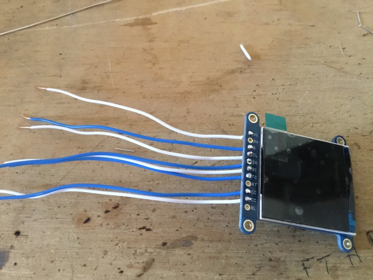 Soldered Wiring
Silicon used to secure it to the cover.
Schematics, diagrams and documents
CAD, enclosures and custom parts
Code
Credits
Related products


Leave your feedback...