
Multiplying Multiplexers In Arduino

About the project
Multiplexing Arduino Inputs: 16 Analogue Sensors on 2 Analogue Pins! Full video and written tutorial on how to read a full 16 potentiometers from only 2 analogue pins!
Project info
Difficulty: Moderate
Platforms: Arduino
Estimated time: 1 hour
License: GNU General Public License, version 3 or later (GPL3+)
Items used in this project
Hardware components

Story
 This is a follow on from my last post
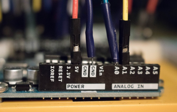
Using a single multiplexer chip on the Arduino to create eight inputs takes up five pins – four digital, and one analogue. Other than ‘converting’ the digital pins to analogue, this doesn’t seem particularly impressive in terms of pin efficiency. However, the benefits of multiplexing become more apparent as you add extra multiplexers to the circuit.
Adding a second CD4051B chip is very similar to adding the first. The main point of interest here is that you can use the same digital pins on the Arduino to send the binary messages to the multiplexer. This starts to make multiplexing very pin efficient, as each chip only requires a single analogue pin to transmit information over.
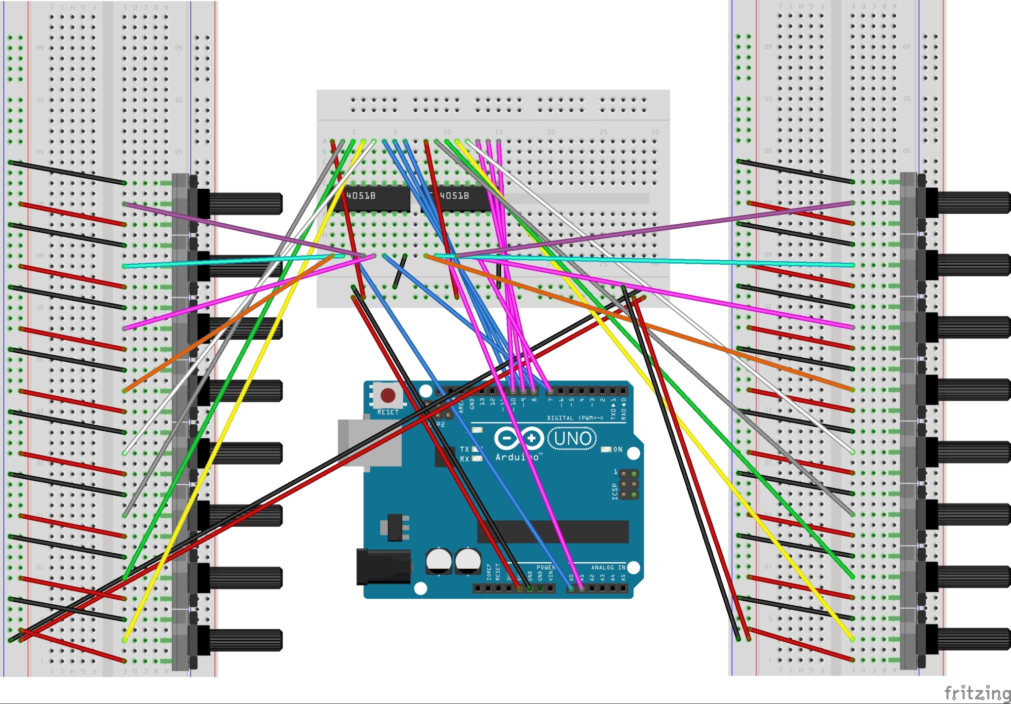
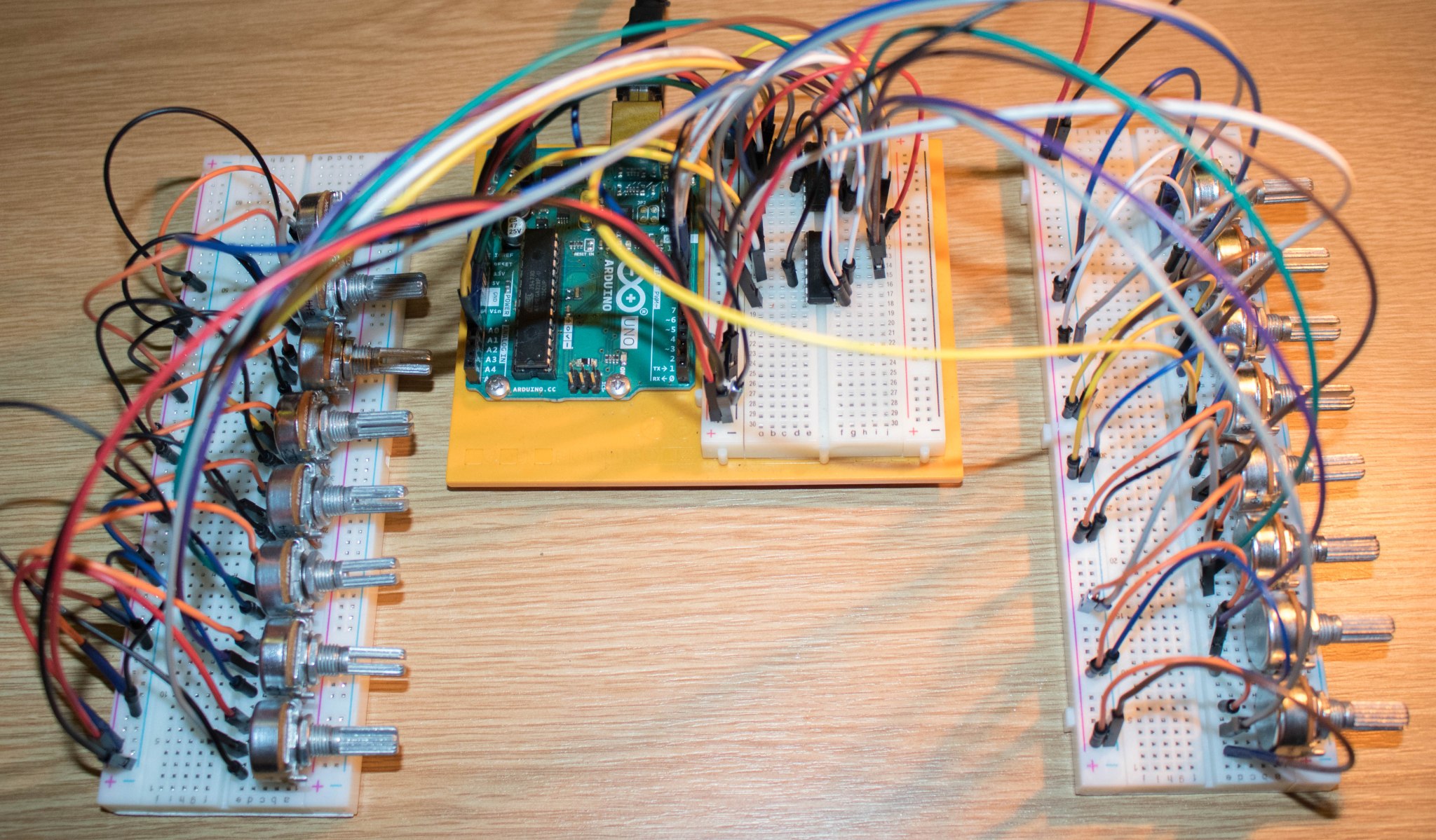
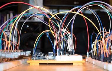
You can have as many multiplexers as you have available analogue pins, meaning an Arduino Uno with six analogue pins can read 48 analogue inputs. With a bit of thought, you could add multiplexers to each input pin of the first multiplexer – but this would involve changing the code around significantly. One of the main disadvantages of using multiplexers is the waiting time between each read – installing a multiplexer through another multiplexer necessitates longer wait times, as each pin on the first chip needs to be read multiple times before moving on.
Video Explanation
The CodeBecause there are now 16 independent inputs coming into the serial monitor, it becomes increasingly difficult to read. I plan to use these numbers in a Max patch, so I mainly need to get the text into a format that is easily read by Max.
I figured out that the best way to do this was to send all of the numbers as a list, without naming them, with spaces between each integer (this, honestly, makes the serial monitor look clearer too). Max can read the list as 16 distinct numbers, and an unjoin object can be used to separate this into the 16 potentiometer values. I will go into more detail on the max patch in my next blog post.
References:
Gammon, N., 2013. Microprocessors: 74HC4051 Multiplexer/Demultiplexer. [online] Gammon.com.au. Available at: http://www.gammon.com.au/forum/?id=11976 [Accessed 25 November 2020].
Code
Credits
Related products


Leave your feedback...