
Mobile App For Esphome Devices On The Example Of Led Control

Made by 2Smart / Holidays / Home Automation / Lights / IoT
About the project
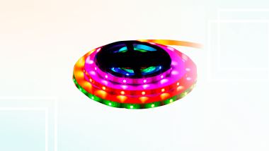
An ESP32-based Wi-Fi controller for addressable LED strips is controlled via a mobile application as well as other methods such as voice commands, a phone call, and a Telegram bot. This controller is just an example of an ESP32-based smart device with ESPHome firmware, for which a modern mobile application is available.
Project info
Difficulty: Easy
Estimated time: 3 hours
License: GNU General Public License, version 3 or later (GPL3+)
Items used in this project
Hardware components

Story
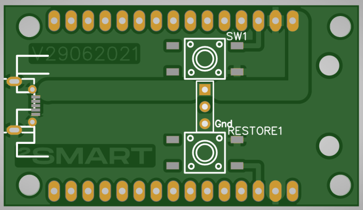
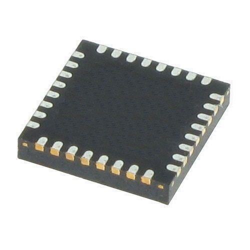
Controller board assembly
All technical materials on creating a controller, including a printed circuit board project, can be found on the 2Smart Cloud GitHub. First, you need to use the Gerber project to order or make your board.
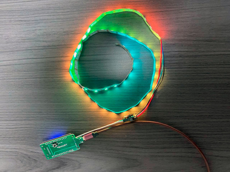
Let’s assemble the controller using the board and necessary components:
Controller firmware
After assembling the device, you just need to flash it and start using it for its intended purpose. You can use the SDK-based firmware code from GitHub, but there is an alternative, and this is ESPHome.
In many cases, ESPHome is a fairly functional tool. Its main advantage is simplicity. Using ESPHome, it will be easier for you to modify the firmware and add new functionality — for example, connect additional sensors and create a smart multitool.
We are using a simple LED controller as an example. You can connect any ESPhome-based device and will have access to all further mentioned features.
Documentation and ready-made examples for ESPHome will help you write the code. We used such sources:
a platform for controlling RGB components - https://esphome.io/components/light/fastled.html;
a library of standard effects and instructions for writing your own - https://esphome.io/components/light/index.html#light-effects.
After selecting the appropriate lines of code, we added controller effects and included support for the Reset button and Wi-Fi signal sensor in the firmware.
Full code from our example:
- light:
- - platform: fastled_clockless
- chipset: WS2812B
- pin: 18
- num_leds: 300
- rgb_order: GRB
- name: FastLED WS2812 Light
- id: light_rgb
- effects:
- - random: null
- - pulse:
- name: "Fast Pulse"
- transition_length: 0.5s
- update_interval: 0.5s
- - strobe: null
- - addressable_scan:
- move_interval: 50ms
- scan_width: 4
- - addressable_random_twinkle:
- twinkle_probability: 20%
- progress_interval: 100ms
- - addressable_color_wipe: null
- - addressable_rainbow: null
- - addressable_fireworks:
- name: Fireworks Effect With Custom Values
- update_interval: 32ms
- spark_probability: 10%
- use_random_color: false
- fade_out_rate: 120
- binary_sensor:
- - platform: gpio
- id: led_switch
- pin:
- number: GPIO5
- mode: INPUT_PULLUP
- inverted: true
- name: Led switch
- on_click:
- then:
- - light.toggle: light_rgb
- - platform: gpio
- id: change_effect
- pin:
- number: GPIO4
- mode: INPUT_PULLUP
- inverted: true
- name: Change effect
- on_click:
- then:
- - lambda: !<!lambda> |-
- uint32_t total = id(light_rgb)->get_effects().size();
- uint32_t curr_idx = 0;
- uint32_t i = 0;
- std::string curr_effect = id(light_rgb)->get_effect_name();
- auto call = id(light_rgb)->turn_on();
- // set first effect in list
- if (strcasecmp(curr_effect.c_str(), "none") == 0) {
- call.set_effect(1);
- call.perform();
- return;
- }
- for (auto *effect : id(light_rgb)->get_effects()) {
- i++;
- if (strcasecmp(effect->get_name().c_str(), curr_effect.c_str()) == 0)
- curr_idx = i;
- }
- if (curr_idx == total) {
- call.set_effect(0);
- } else {
- call.set_effect(curr_idx + 1);
- }
- call.perform();
- - platform: reset_sensor
- pin:
- number: GPIO0
- mode: INPUT_PULLUP
- inverted: true
- name: Reset button
- filters:
- - delayed_on: 1s
- sensor:
- - platform: wifi_signal
- name: WiFi1 Signal
- update_interval: 30s
- id: wifi_config
To use a ready-made firmware code to create a device, first of all, you need to create a new product in the 2Smart Cloud developer account:
- Log in to the platform – https://cloud.2smart.com/.
- On the “Products” page, click “Add Product”.
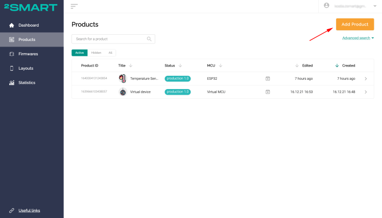
- Select the microcontroller – ESP32.
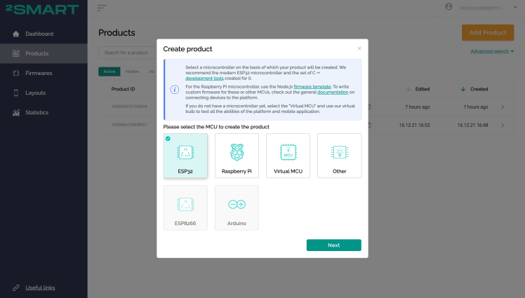
- Click "Add Firmware" and select the ESPHome base.
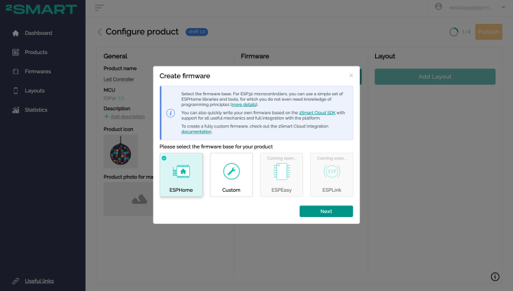
- Paste the controller firmware code into a Configuration field and click the Save button.
- There are two firmware versions for ESPHome-based devices in 2Smart Cloud: test and production.
Test firmware is only for prototype testing. Its unfamiliarity is that the code contains technical data that is not necessary on the end-user’s device. These are parameters for connecting to the platform and interacting with it. For example, your Wi-Fi network credentials.
Production firmware is the version that is installed on devices that will go on sale. Its code no longer contains any Wi-Fi credentials and the device is connected to the platform using a standard pairing method from the end-user’s account.
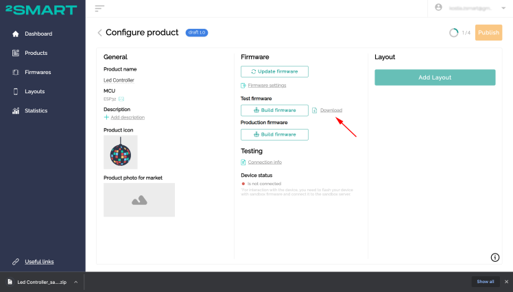
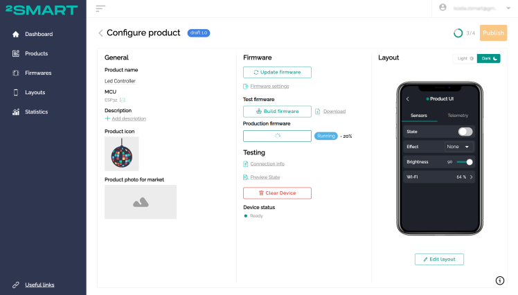
- Click "Build Firmware” for the test device. Enter the credentials of your Wi-Fi network – they will be transmitted to the device in the test firmware code for a quick Internet connection.

- Wait until the firmware building is completed. Click "Download".
- Connect the controller to the computer using a USB cable.
Attention! Disconnect the LED strip from the controller before proceeding with the flashing! - Unpack the downloaded archive, and enter the folder with the received files. Flash the device using Mac OS, Linux, or Windows device.
- After completing the firmware installation process, return to the platform – the device will connect to it automatically. The successful connection is indicated by a green indicator and the Ready status in the "Device Status" field.
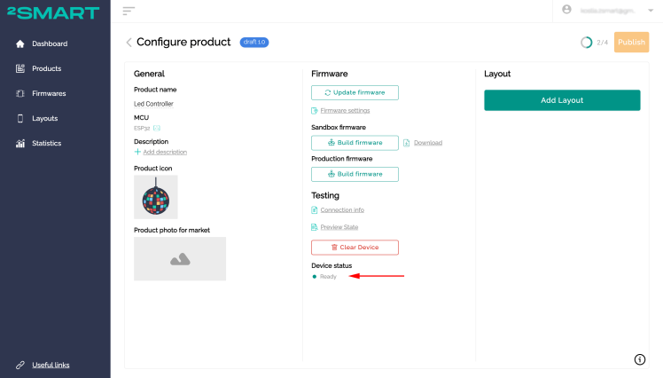
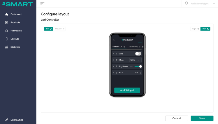
- Click "Add Layout" to open the mobile application emulator. Configure the interface of the mobile application to control the device.
- Install the 2Smart Cloud mobile application (iOS | Android) and log in with the same username and password that you used to register in the developer's account.
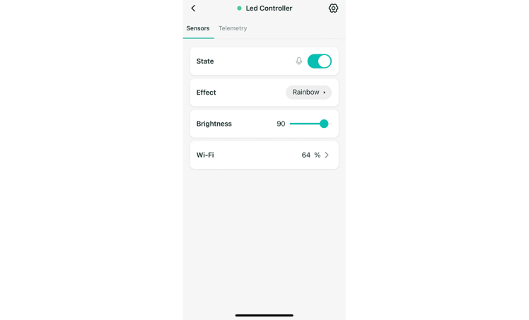
- Your new device is already displayed in the app. Please test the functionality of all widgets.
- Return to the platform and click "Build Firmware" for the production device. The final version of the firmware will be built. Download the archive.
- Click "Publish", and the product will be available to you and your users for pairing with a mobile device.
- Flash the device with production firmware similar to the test firmware. Do not forget to clear the memory of the microcontroller beforehand.
Attention! Disconnect the LED strip from the controller before proceeding with the flashing! - Return to the mobile application, and log in with any parameters as a regular user.
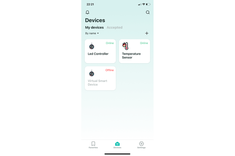
- Click the "Add Device" button on the "Devices" screen – the pairing procedure will start.
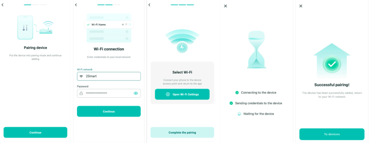
- After the pairing is completed, your LED strip controller is displayed on the Devices screen. Make sure you can control it from your smartphone screen.
Mobile app features
Here are the additional benefits of each 2Smart Cloud device available out of the box:
- Easy and fast integration with Siri and Google Assistant. You can use custom voice commands, shortcuts, and other features of the built-in assistants.
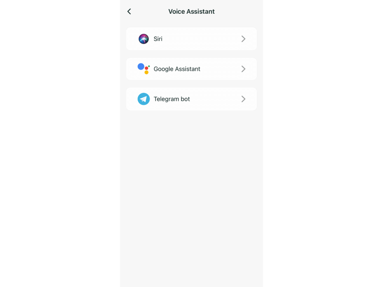
- Device management using a free phone call.
- Device management using a Telegram bot.
- Sharing the device with other users.
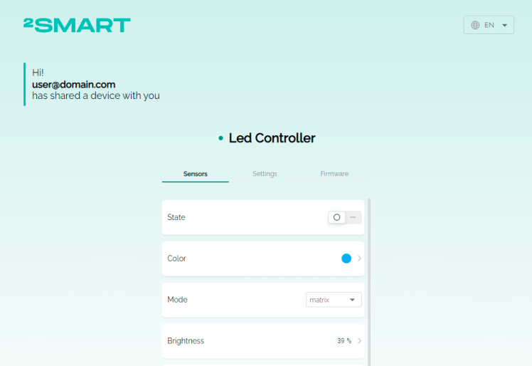
The mobile application and all its additional features are free. You can configure its interface to suit your needs and make changes to the interface at any time.
Results
We have created a LED strip controller without programming and using assembler programs. The firmware code for ESPHome was written according to the documentation for this base. We just took ready-made examples and used them on our device.
Similarly, you can create any other ESP-based device and use ESPHome to write the firmware. By connecting such a device to the 2Smart Cloud, you will be able to use pairing with a mobile application and take full advantage of the platform.
The 2Smart Cloud free plan allows you to connect up to 20 devices to the platform. If you need more, we offer a reasonable pricing. And if necessary, our experts will also share with you in-depth expertise in the field of IoT.
Code
Credits
Related products


Leave your feedback...