

Mike's Robot Dog

Made by electrouser778 / 3D Printing / Robotics
About the project
Boston Dynamics' robot dog, Spot Mini is unavailable at any price. A Chinese copy is $30,000. Cut 99% of the cost and build one at home.
Project info
Difficulty: Expert
Platforms: Arduino
Estimated time: 2 weeks
License: GNU General Public License, version 3 or later (GPL3+)
Items used in this project
Hardware components

Story
Details
THE PLAN
Increase torque of legs
Decrease weight of legs
Build a stiff, low weight body
Stand on three legs
Add tilt sensors to facilitate adjustments when moving
Take steps
Add onboard power
Stand
Take steps
Add head with sound interaction
I had to show this . . . Google's AIY Vision Kit can be used to detect human faces or smiles (and probably other things). This will allow my dog to "know" that someone is there and if they are smiling. More information can be found in log number 10, "Google AIY Vision."
Spot Mini is an amazing (perhaps scary) robot dog built by Boston Dynamics--not for sale.
If you want to purchase something similar, a company in China produces a research platform for around $30,000. Another legged platform, Anymal, can follow you into an elevator.
Using a 3d printer, off the shelf servo motors, an Arduino and a couple of ultracapacitors; I have started something along the same line--but the cost is more like $300.
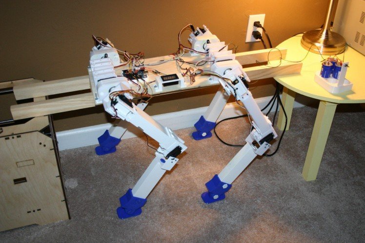
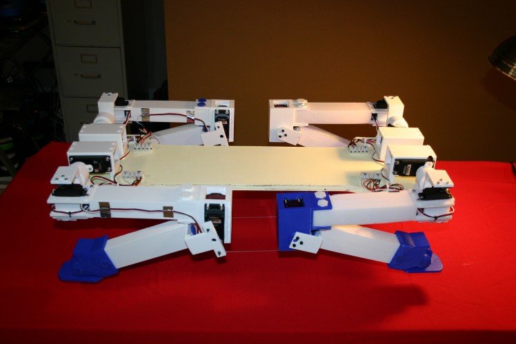
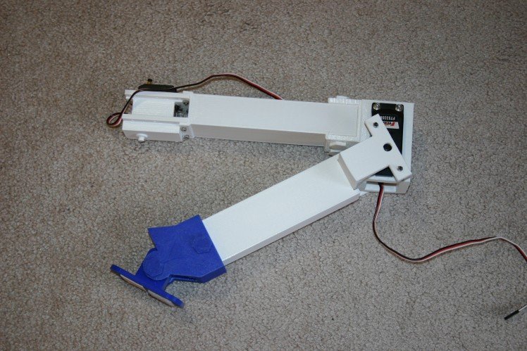
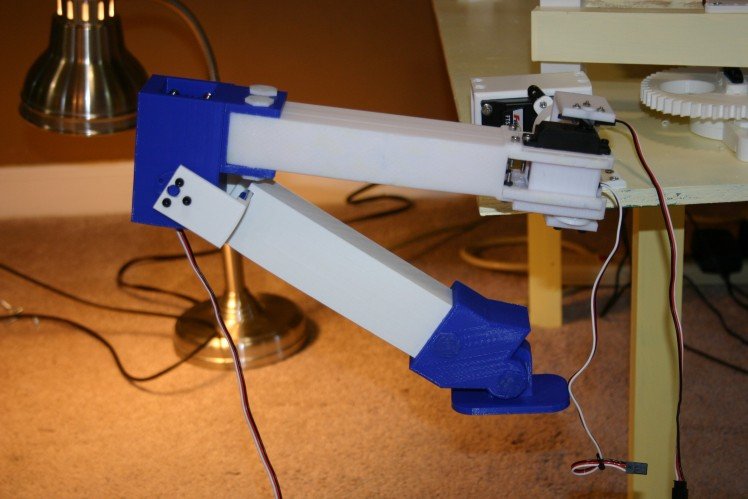
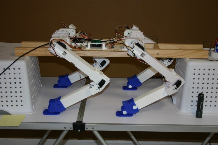
She's young and shaky, but my dog can now stand. The body is longer and the rear legs reversed--look to my log, "The Forces Are Not All With Me."
Here's where we "stand" on March 28.
This is where it started.
If you want to use the 3d print files (and some of the design files) go to thingiverse.com. Some of my .stl files do not have a corresponding design file because the .stl files are 1) the combination of two or more .stl files in Tinkercad or 2) they are mirror images of .stl files, mirrored in Tinkercad. The leg pieces can take 10-12 hours each to print as they are sizable.
I use twelve high torque (277 oz.in) metal gear servo motors at a cost of about $18. each. These have no end stops and they draw a fair amount of current to move, but they respond consistently to commands.
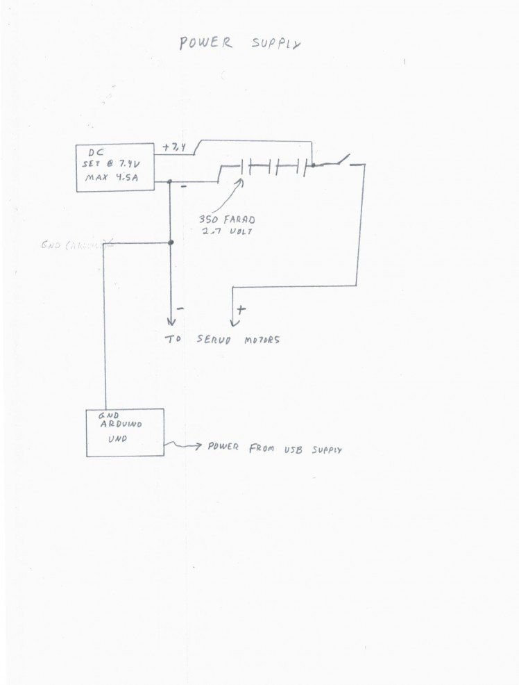
Under heavy load, each servo motor draws 3.5 to 4.5 amps. To move from a sitting to upright position, eight motors need to provide significant torque--meaning 30 to 40 amps are required for a second or so. I use three 350 farad ultracapacitors (in series) across my motor power supply and they take care of the momentary load of the servo motors.
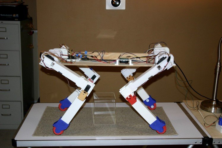
Here's where I am on March 16.
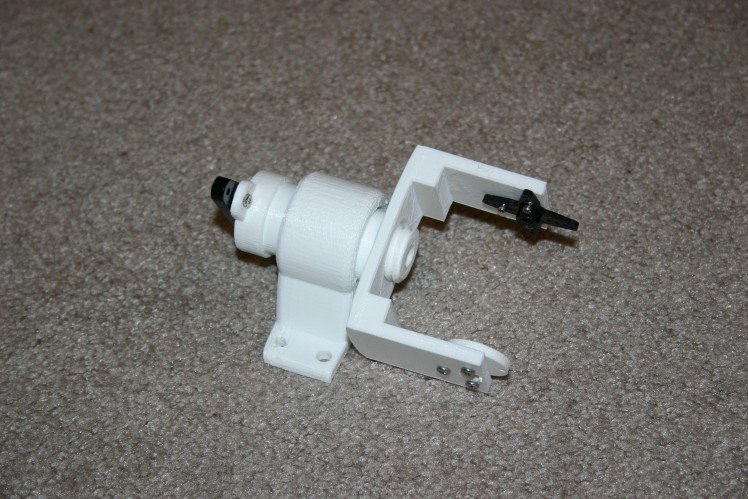
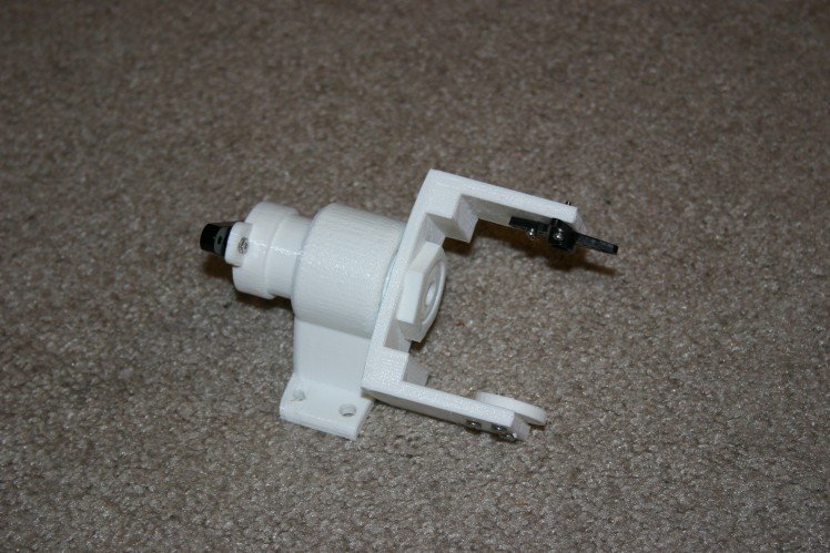
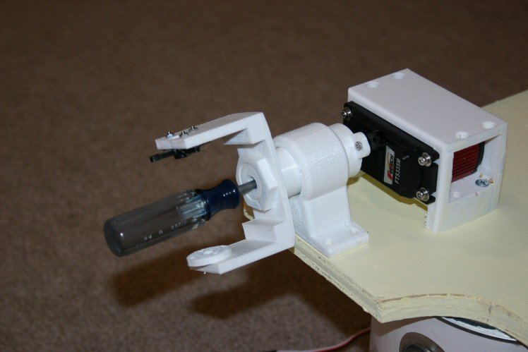
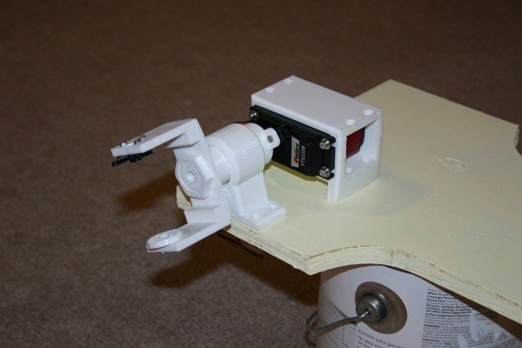
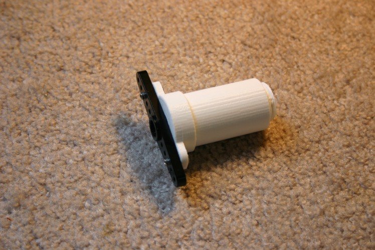
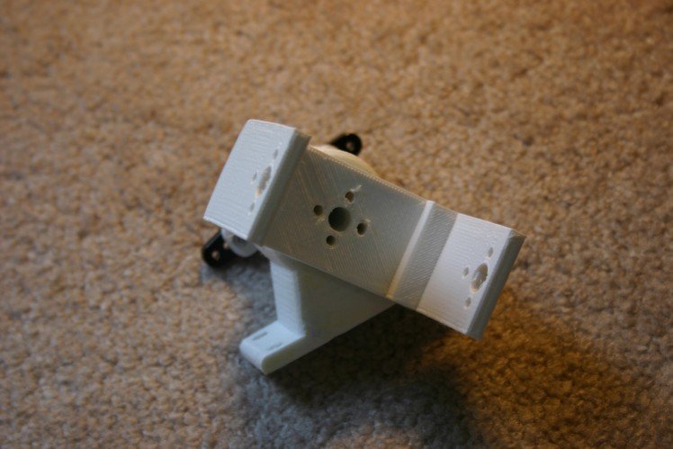
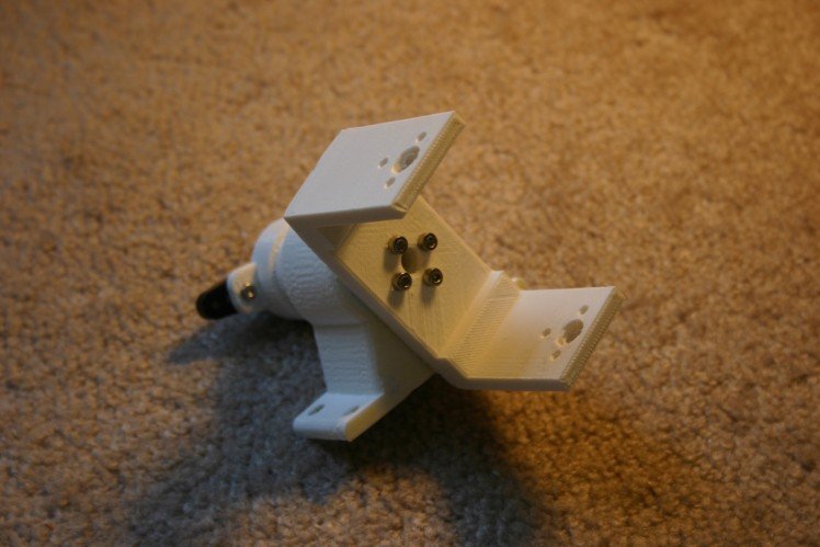
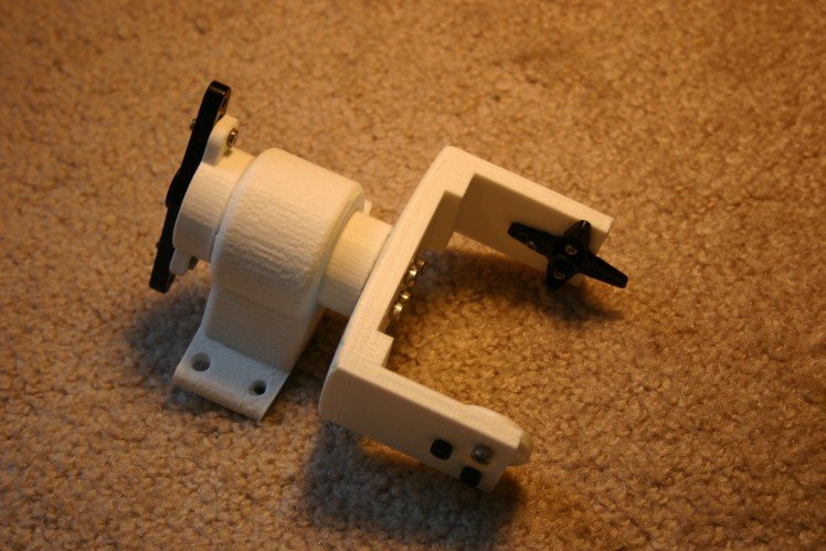
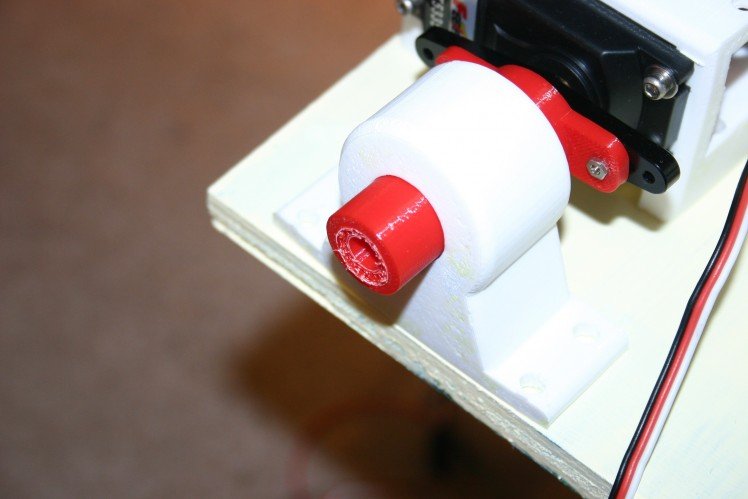
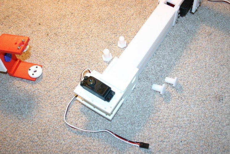
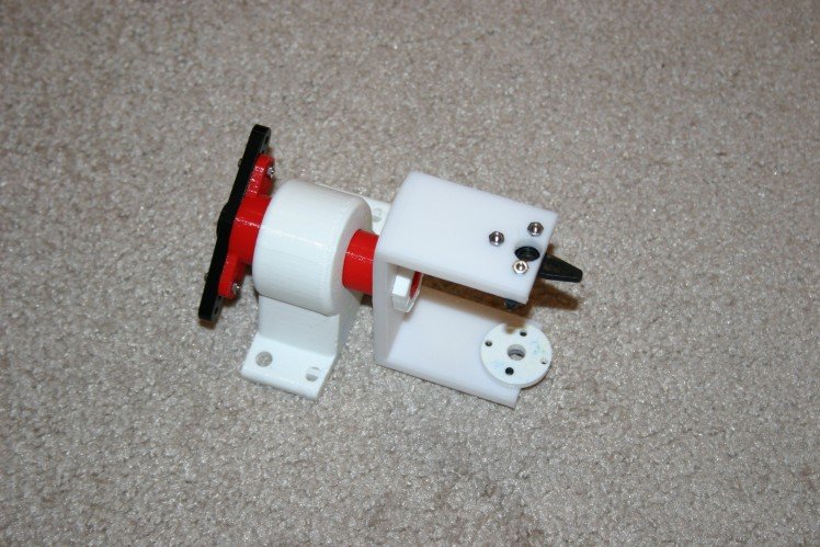
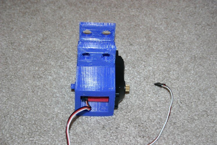
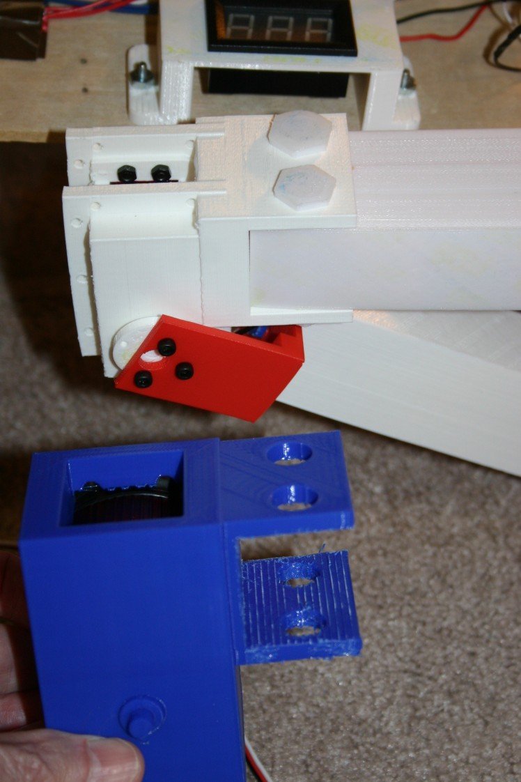
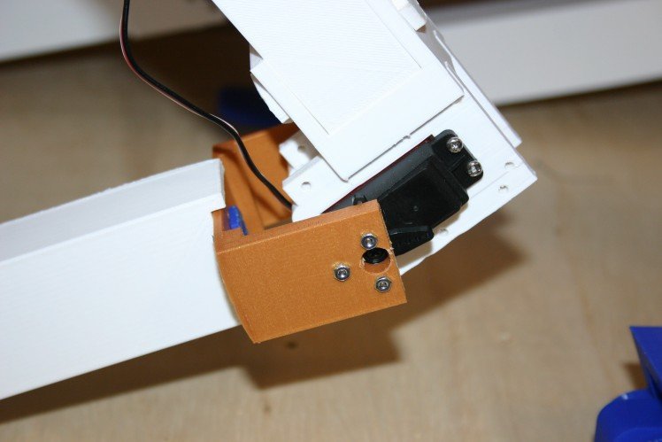
My first "shoulder connection" put all the "up/down" and "rotate" stress on the servo motor.
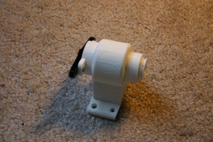
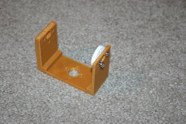
This looked like a bad idea, so I created a bearing block and heavy shaft to absorb the "up/down" load and let the servo motor's gearing handle the rotation only.
The bearings are snowmobile bearings available on Amazon.
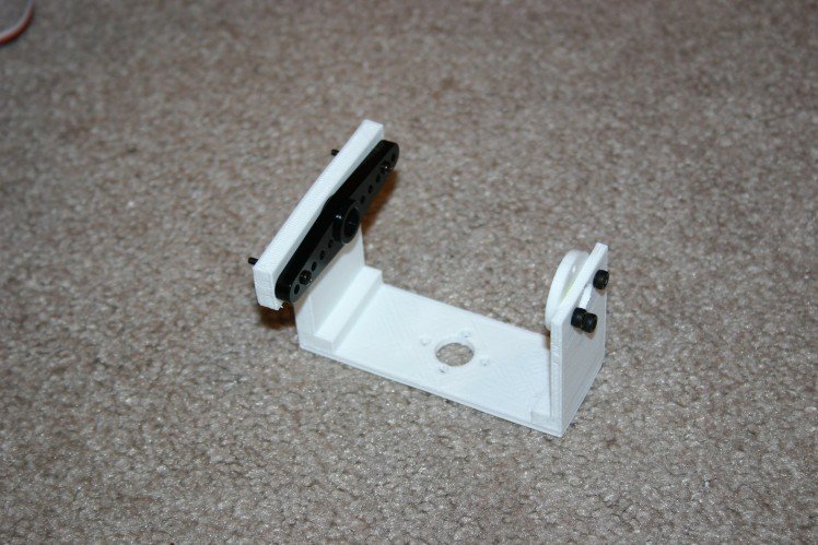
I designed the servo motor mounts such that there is a sort of "back bearing" opposite the shaft so that it is easier to attach moving limbs.
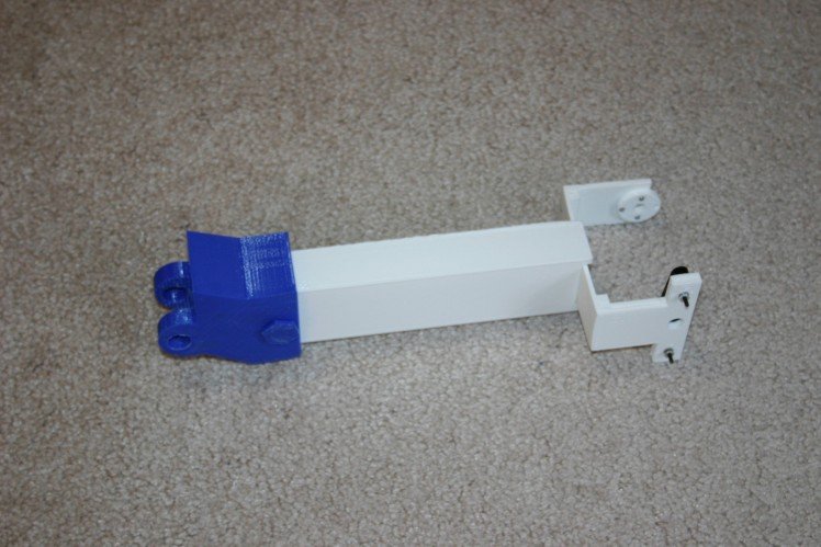
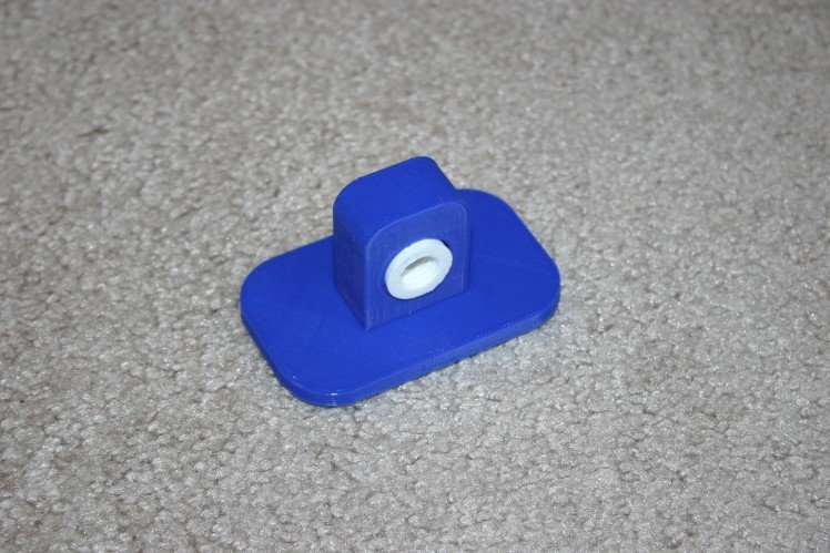
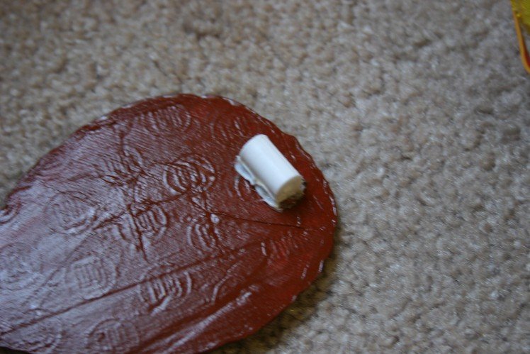
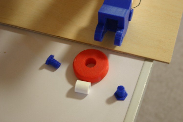
The first foot was a wheel--but that rolled all over the place, so I created a movable flat pad for better traction.
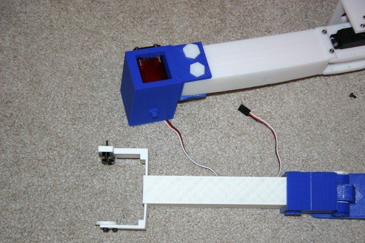
I mounted a digital voltmeter up on the body--just to keep track of what was available for the servo motors.
So, there's a long way to go, but this walkable platform (when it works) will be useful for robotics on smooth or rough terrain.
On February 27, the first attempt at standing was made. A couple of the joints couldn't take full speed movement--we learn by trying!
Now, with the feet not rolling or bending, it is possible to get the front and back to lift together.
Instructions
Leg Module
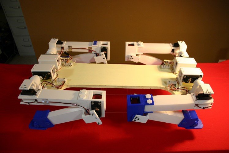
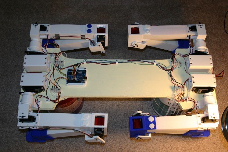
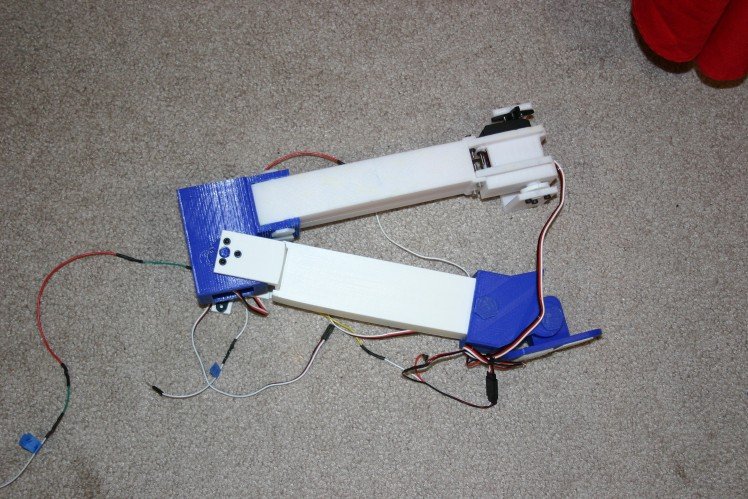
In one week, for less than $500., we can have a four leg module that requires for operation: power, control for 12 servo motors, sensors.
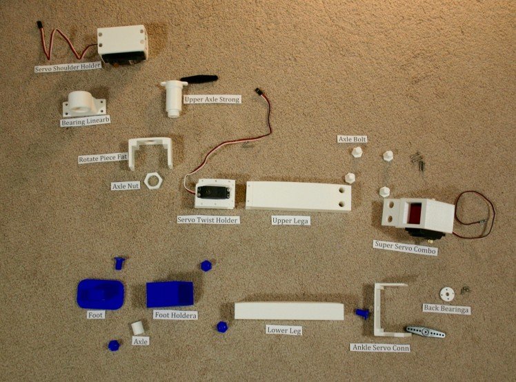
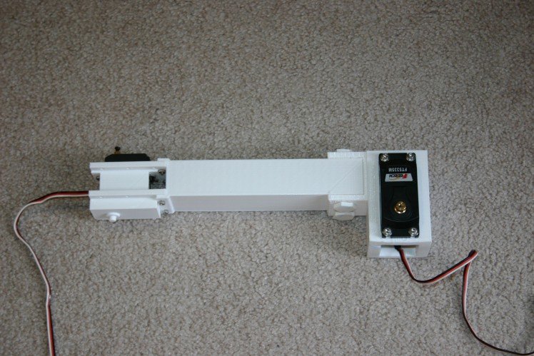
Here's what the module should look like:
Let's start with a list of materials needed. First, there are the 3d printed parts (files available on this site).
(4) Super Servo Holder
(4) Upper Axle Strong
(8) Back Bearinga
(4) Rotate Piece Fat
(4) Bearing Linear
(4) Axle Nut
(4) Upper LegA
(4) Super Servo Combo
(36) Axle Bolt
(4) Ankle Servo Conn
(4) Lower Leg
(4) Foot Holdera
(4) Axle
(4) Foot
(4) Wire Guide
Other Parts:
(32) m3 x 16mm bolts
(32) flat washers for m3 bolts
(48) m3 nuts
(8) FT 5335M servo motors (Pololu.com)
(8) aluminum horn for FT 5335M servo (pololu.com)
(20) 2-56 x 7/16" bolts
(28) 2-56 nuts
(24) m3 x 8mm bolts
(4) 20 kg-cm servo motor (amazon.com)
(16) m3 x 12 mm bolts
(8) 2-56 x 3/4" bolts
(8) lockwashers for 2-56 bolts
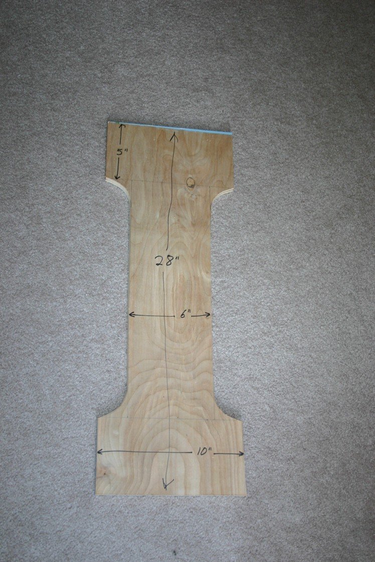
(1) plywood body 1/2" plywood 28" x 10"
(1) paint for plywood body
(16) #6 x 1 1/4" wood screws
(24) #6 x 3/4" wood screws
(4) 5 position terminal blocks
(4) number 4 x 1/2" wood screw
(4) servo extension cable
(1) aluminum duct tape (or any other tape)
(4) small tie wrap
For the body, I examined several materials and decided to go with 1/2" plywood. The body requires about 200 square inches of material. Below are some of the materials considered:
1/4" plywood 2.15 grams per square inch
1/2" plywood 4.3 grams per square inch
1/4" acrylic 4 grams per square inch
5 mm foam board .59 grams per square inch
1/4" plywood is too flexible--I had bending problems requiring support on the early dog versions.
5 mm foam board looks great in theory, but I had doubts about the stiffness and my ability to connect things securely.
1/4" acrylic would look "cool," but it's not so easy for me to work with.
I examined carbon fiber sheets, but that looked like a project unto itself.
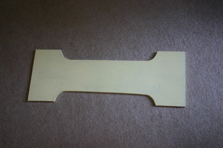
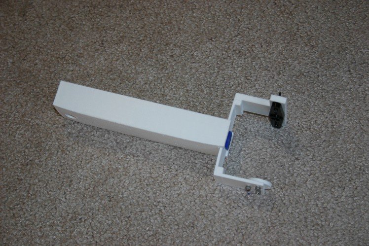
I cut the plywood in a shape to reduce the weight.
Then, I painted the plywood.
Assembling the Leg
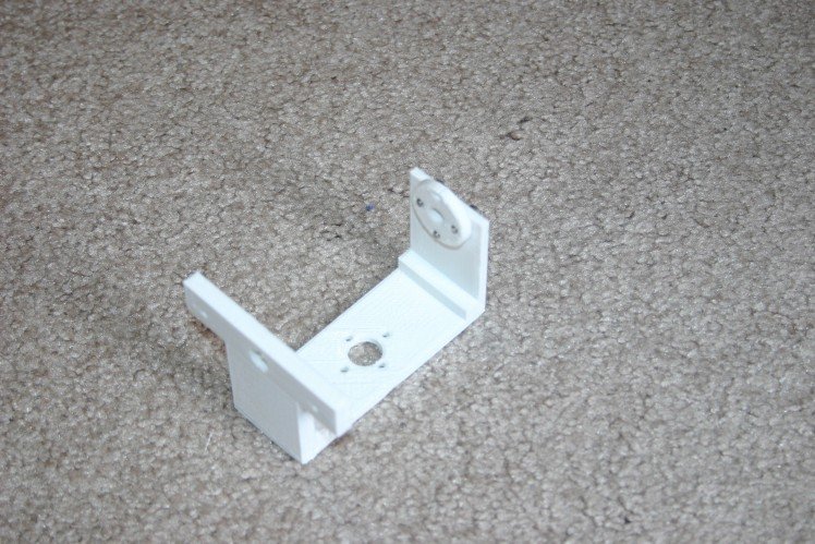
Here's the main pieces.
Attach a servo motor to "Super Servo Holder" using (4) m3 x 16 mm bolts, nuts and flat washers.
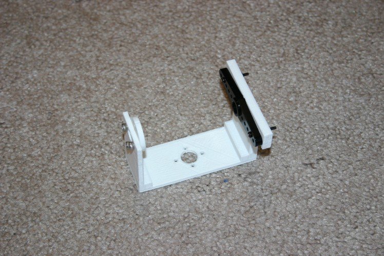
Set the left front shoulder servo to the ccw rotation maximum, 150 degrees.
Attach the "Upper Axle Strong" to the aluminum servo horn using (2) 2-56 x 7/16 bolts and nuts.
Attach "Back Bearinga" to "Rotate Piece Fat" using (3) m3 x 8mm bolts. Attach servo horn (from 20 kg-cm servo) to "rotate piece fat" using (3) 2-56 x 7/16" bolts and nuts.
Slide "Upper Axle Strong" through "Bearing Linear."
Thread "Rotate Piece Fat" onto "Upper Axle Strong."
Tighten "Axle Nut" onto "Upper Axle Strong."
Set Servo Twist Motor to 90 degrees. Attach "Servo Twist Holder" to "Upper Lega" using (4) m3 x 12 mm bolts and nuts.
Install motor in "Super Servo Combo" using (4) m3 x 16 mm bolts, nuts and flat washers.
Attach "Super Servo Combo" to "Upper Lega" using (4) 3d printed "axle bolts."
Set "Super Servo Combo" motor to cw max--30 degrees.
Attach "back bearinga" to "Ankle Servo Conn" using (3) m3 x 8 mm bolts.
Attach aluminum servo horn to "Ankle Servo Conn" using (2) 2-56 x 3/4" bolts, nuts and lockwashers.
Connect "Ankle Servo Conn" to "Lower Leg" using (1) "Axle Bolt."
Connect "Foot Holdera" to "Lower Leg" using (2) "Axle Bolts."
Place "Axle" in "Foot." It's a loose fit.
Insert foot/axle into "Foot Holdera."
Secure foot using (2) "Axle Bolts."
Connect lower leg assembly to upper leg assembly by attaching "Ankle Servo Conn" to servo motor. Leg should be in sitting position. Insert servo horn screw and tighten.
Adjust "Rotate Piece Fat" so that leg will be in sitting position. Insert servo horn screw and tighten.
Place "Servo shoulder holder" and "Bearing Linearb" on plywood body. Assume sitting position for dog. Secure using (4) number 6 x 1 1/4" screws and (4) number 6 x 3/4" screws.
Insert servo twist motor into "Rotate Piece Fat." Install and tighten servo horn screw.
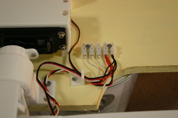
Install 5 position terminal block using (2) number 6 x 3/4" wood screws.
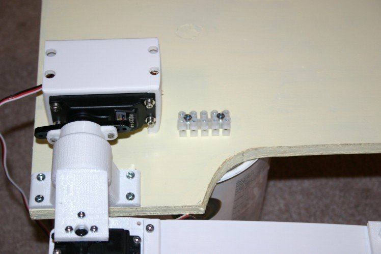
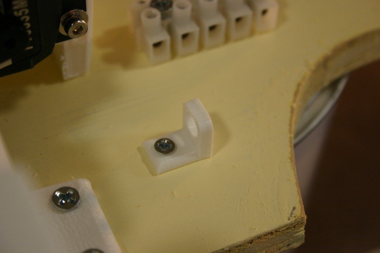
Install wire guide. Use (1) number 4 x 1/2" wood screw.
Connect servo extender cable to "Super Servo Combo" servo motor.
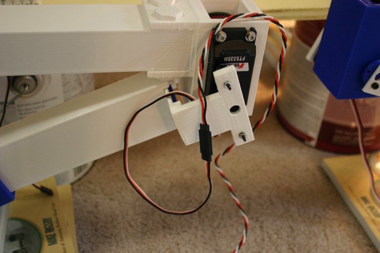
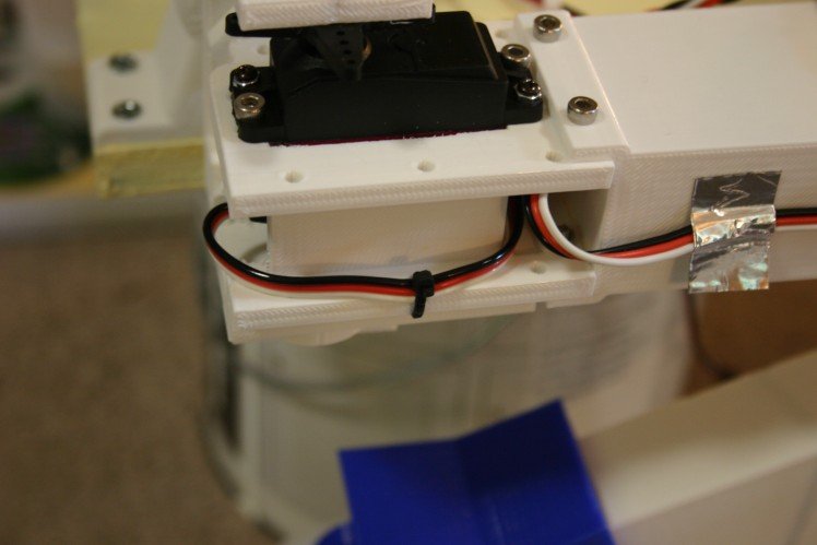
Route cable and secure using duct tape. Secure servo wire to "Servo Twist Holder" using a tie wrap.
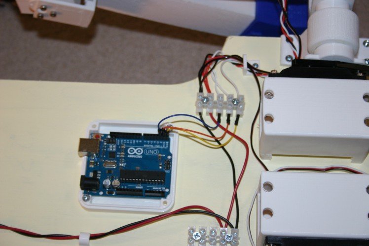
Secure wires in terminal blocks. From outside looking in, position number 1 (left most) is upper servo control wire. Position 2 is "servo twist" control wire. Position 3 is lower ("super servo combo") control wire. Position 4 is positive. Position 5 is negative.
Do this three more times. Left front and right rear legs are the same.
Right front and Left rear legs are set up with the "Servo shoulder motor" set to the maximum cw limit (30 degrees) instead of 150 degrees.
Project Logs
Non Slip Joint
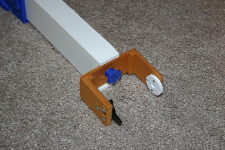
In the upper leg joint--in spite of all my best efforts at making the joint tight--I continue to have slipping. To correct this, I modified the joint, inserting machine screws to prevent slippage.
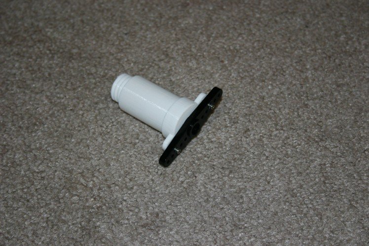
I printed (4) axles with shorter threads, then attached the servo horns.
I slide this piece ("axle shorter thread") through "bearing linearb."
Thread "fat pieceb" onto this.
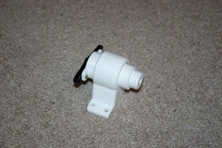
Drill holes 25 mm deep using a 7/64 inch drill bit. Install (4) 20 mm M3 machine screws.
Add the servo horn and back bearing piece, then install on all four legs.
This is a significant operation requiring about 20 hours of print time and 8 hours of installation time.
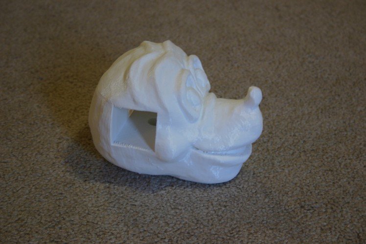
Dog's Head
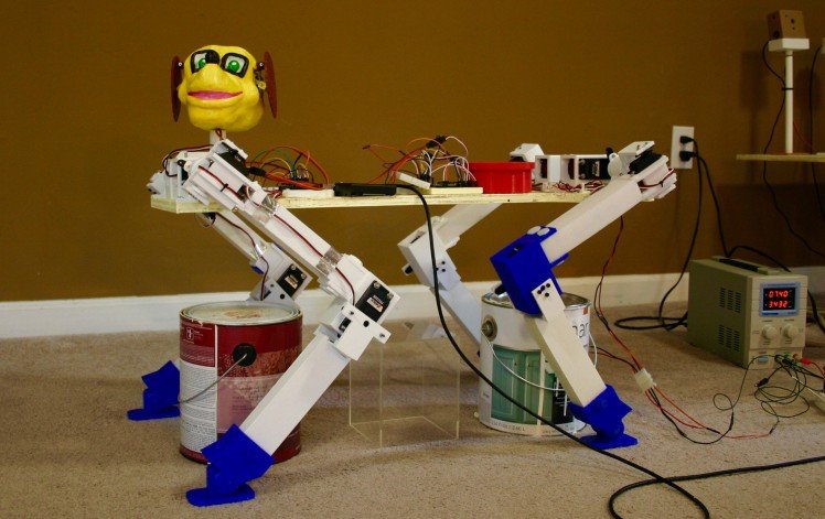
Here's the first version of a head--with flapping ears synchronized to barks.
I don't have a dog, so we had to visit a friend and record their dog's bark. Of course, Juston (the dog) just stood silently for all the many things that normally trigger a bark (treat, knock on the door, promise of a car ride). Finally, he was induced to talk.
This "Dog Head Module" is a 3d printed head with two servo motors that can be used to flap ears. It can be added to any dog robot (wheels or legs) and modified (the raw head files are available on this site).
My wife, Annelle, made a clay head for scanning.

The head is fairly large and was scanned on a Makerbot Digitizer.
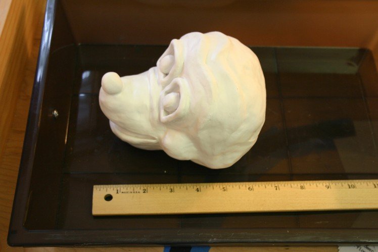
The resulting scan file (included) was too large to import into Tinkercad. I reduced the file size (included) then imported the head into Tinkercad and made holes for the servo motors and wires.
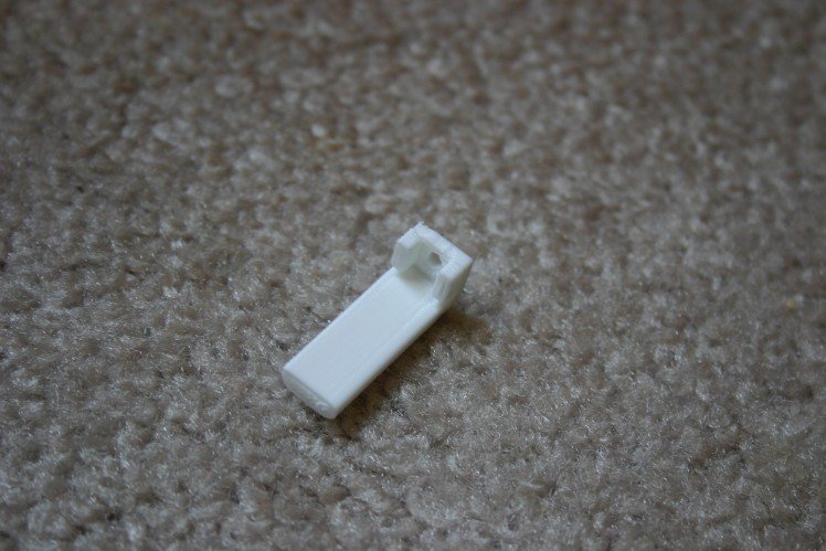
I mounted the micro servo motors in their 3d printed brackets, then melted (using a soldering iron) the bracket into the head.
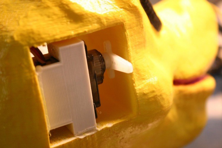
I added a servo horn extender to the servo horn so that the ear would move a reasonable amount.
Bearing brackets (3d printed) were melted onto the dog's head. They accommodate the 1 1/4 inch by 2-56 machine screws that allow the ear to move.
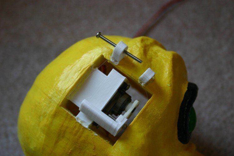
A bearing adapter piece must be melted to each ear.
A finished (not painted) ear looks like this.
Back to the art shop (Annelle) for a paint job.

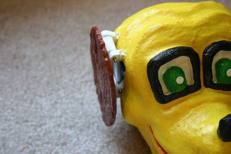
Assembled, the head looks like this.

I used an Adafruit sound module board and trigger the bark file (included on this site) with an Arduino. I coordinated the ear flapping servo motors with the bark sound.
You could put square 8x8 led modules in for the eyes. The mouth could be cut away and modified to move for the bark . . . this is just a starting place.
Tilt Module
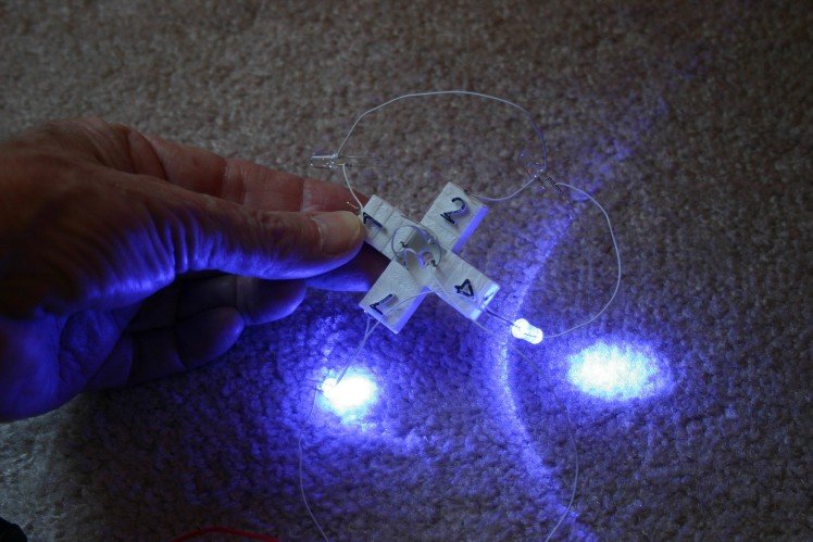
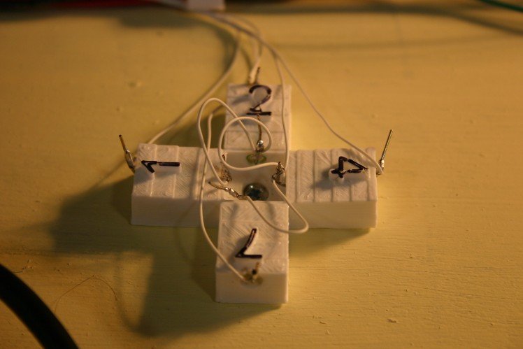
This low cost module using four roller switches and a 3d printed bracket can be used to provide tilt information for a robot.
The idea is to use four roller ball tilt switches (about $.50 each from Amazon) and a 3d printed bracket to detect tilt. I designed a four degree tilt to each of the four "arms" so that the balls would roll downhill when the robot is level. By assigning the numbers "1" for north, "2" for east, "4" for south, and "7" for west it is possible to read each switch then add the numbers and know whether there is tilt and in what direction.
The leds shown below are just for testing--not part of the finished sensor.
I start with the tilt switch holder and insert the tilt switches. The "not active" end is pointed toward the center (longer wire, silver instead of brass). The "active" end--when lower than the other end--will result in continuity between the end wires.
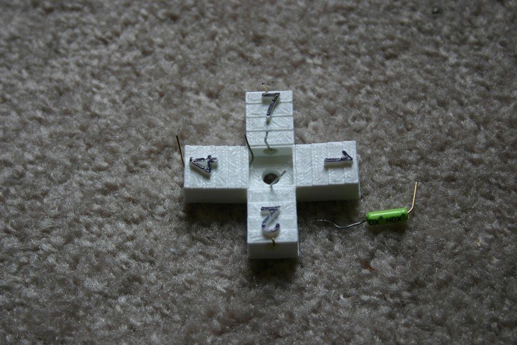
I use wire wrap wire (then solder it) to connect the pins. The center position I tie to ground on the Arduino. Direction one goes to A0, direction two goes to A1, direction four goes to A2 and direction seven goes to A3 (since I used 12 Arduino Uno pins for servo control, I'm running low on input/output pins).
The final assembly, fastened to the dog using a wood screw, looks like this.
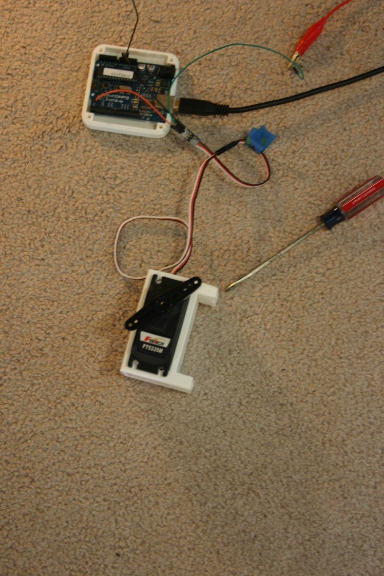
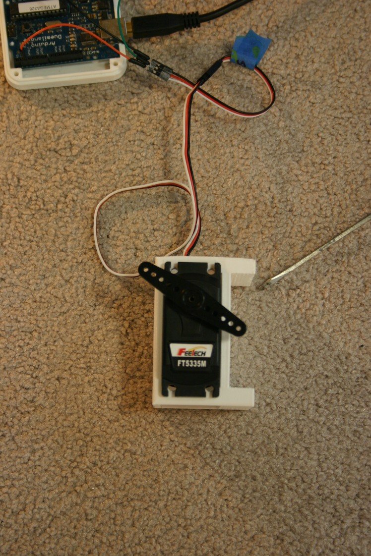
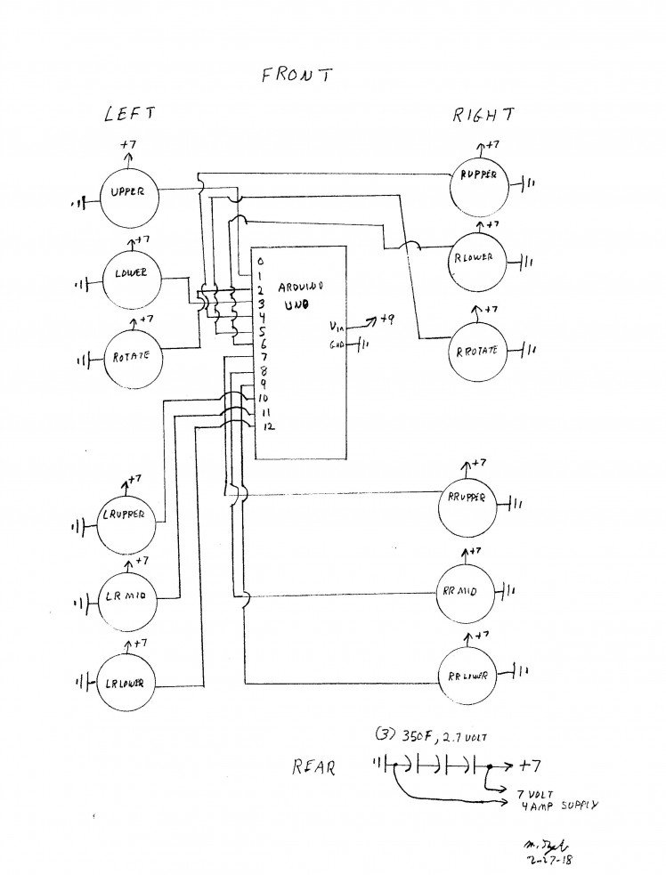
Wiring the Module for Power and Control
To make the module stand requires power and control. Here's a schematic of the power components.
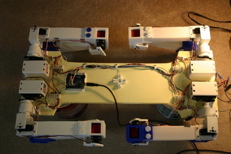
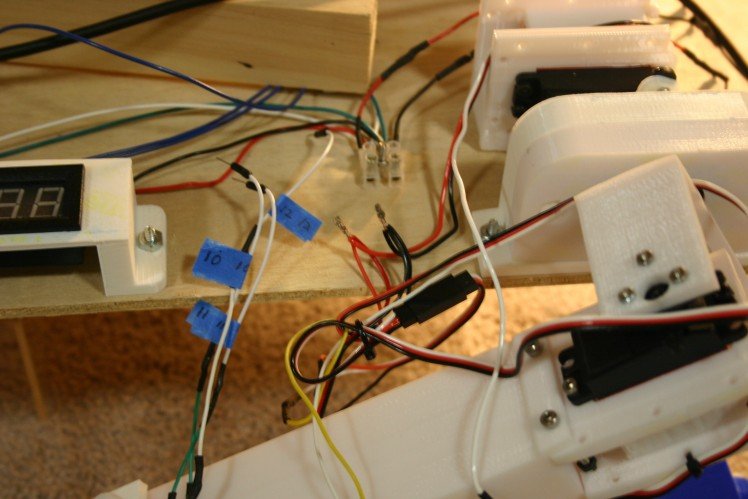
Let's look at the physical wiring. I connected the + and - power blocks using number 18 stranded wire.
I added an Arduino Uno to control the servo motors.
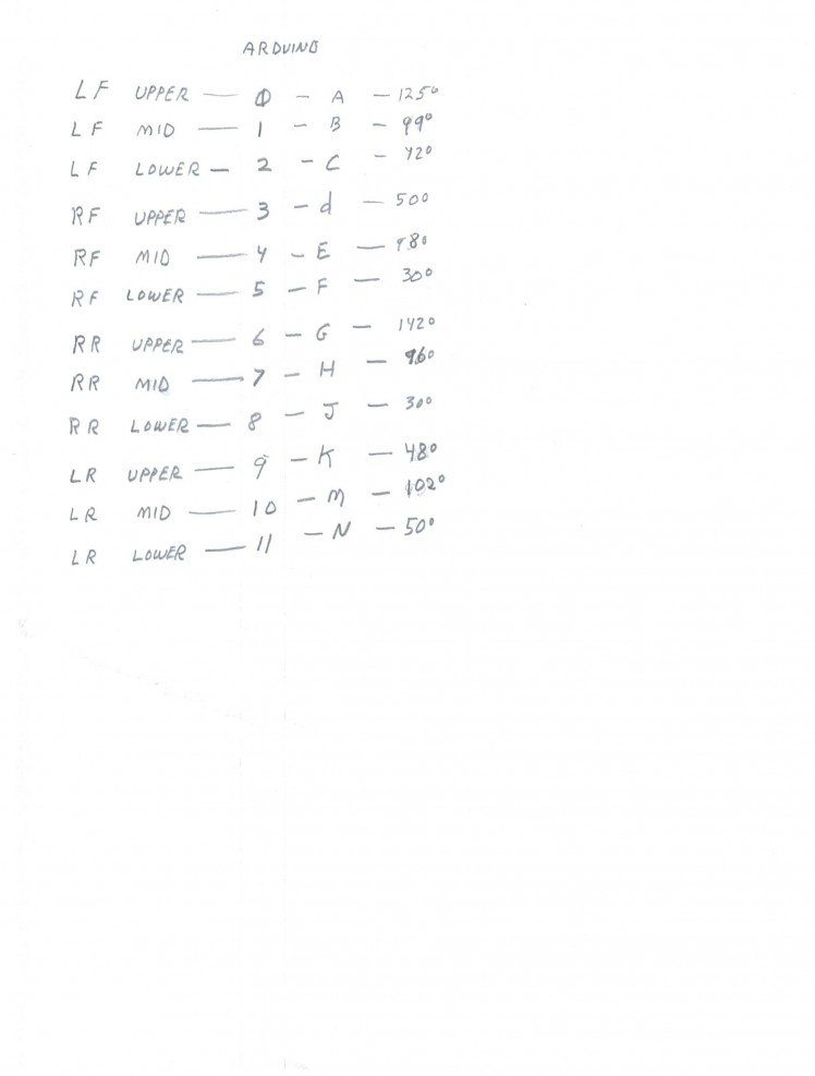
Pins 0 through 11 are connected as follows:
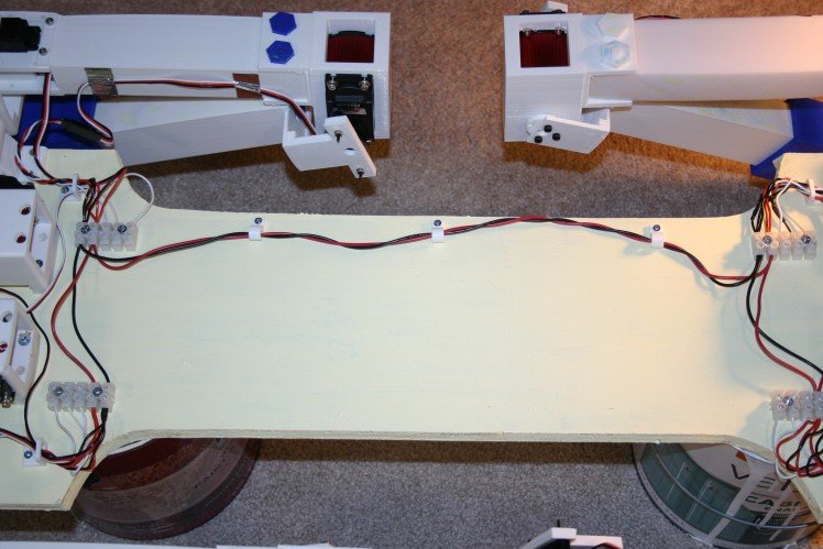
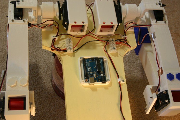
A top view of the connected wiring is shown below.
The starting position for the servo motors on the legs is shown below.
Because each spline on a servo shaft/horn represents about 15 degrees, the servo motors must be operated until a satisfactory position is achieved and that value should be recorded.
The .ino Arduino sketch for standing/sitting on this site as module test 0524.
Here's the standing routine.
Leg Test With High Torque Servo Motors
Today I tested the more powerful leg.
The original leg--using 20 kg-cm servos--could exert 1250 grams of "push" on a scale. The new leg--using 40 kg-cm servos--measured 3300 grams of "push" before the upper plywood test jig lifted. In other words, I'm getting nearly three times the lift with the new motors. The original leg used three $18. motors while the new leg uses one $18. motor and two $38. motors; so my cost per leg just went up $40.
The extra torque was too much for the upper axle piece and it sheared at the connection where it holds the leg.
I reprinted the axle at 100% fill and it is now holding for test purposes. I'm in the process of redesigning the connection for more strength.
An unexpected benefit of the new motors involves a stiff gear train that resists external movement. If I raise the leg in the air and remove power to the servo motors, the leg stays in place.
This is a major benefit in that the motors draw virtually no current (thus no wasted heat and battery energy) unless they are moving.
I'm working on stronger connections and I've ordered enough parts to complete four legs.
Google AIY Vision
I assembled a Google AIY Vision Kit tonight (took about two hours). This will be great for the dog since it will allow the detection of humans and whether they are smiling. I am using the default mode--have not explored the many options at this time.
When no face is detected, the light on top is not illuminated.
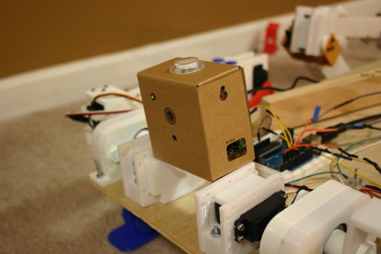
When a face is detected (and it will easily detect a single face at a distance of 20 feet) the light turns blue.
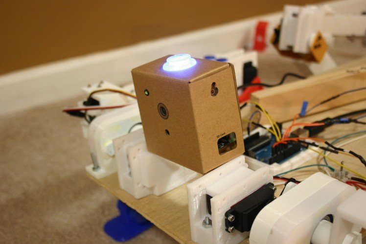
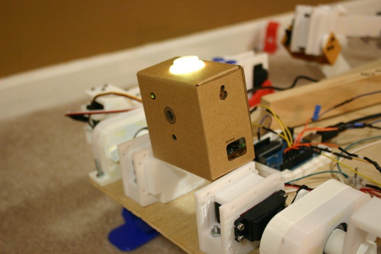
When there is a smile, the light turns yellow. A big smile will turn the light bright yellow and trigger a piezo buzzer.
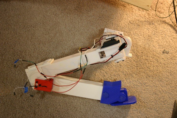
Stronger Leg
I've completed the addition of two larger, more powerful motors (twice the torque of the original servo motors). The files for the changed parts are available on this site.
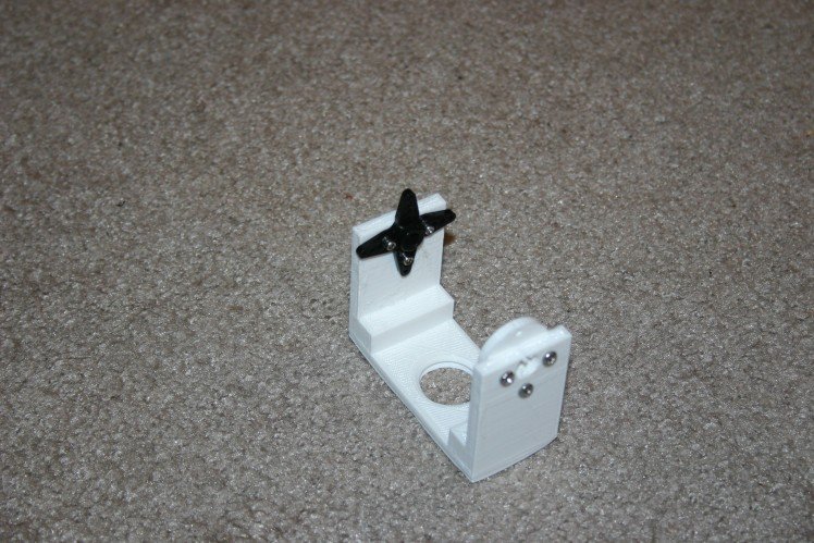
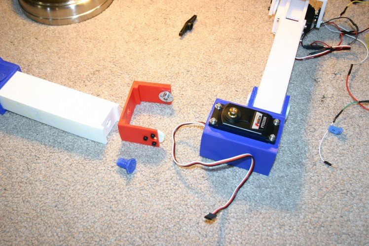
First, I added the aluminum servo horn to the new shoulder axle.
Next, I disconnected the existing elbow joint.
Now, I set the new motor and bracket in a similar position to the old--so I wouldn't mix things up too much.
I mounted the motor to the upper leg.
I attached the aluminum servo horn and back bearing to the ankle servo connector.
I attached this assembly to the lower leg.
I attached the lower leg to the elbow assembly.
I pushed the shoulder axle through the linear bearing and attached it to the upper leg motor bracket.
I attached the servo horn to the servo motor and tightened the locking screw through the hole in the axle/shaft.
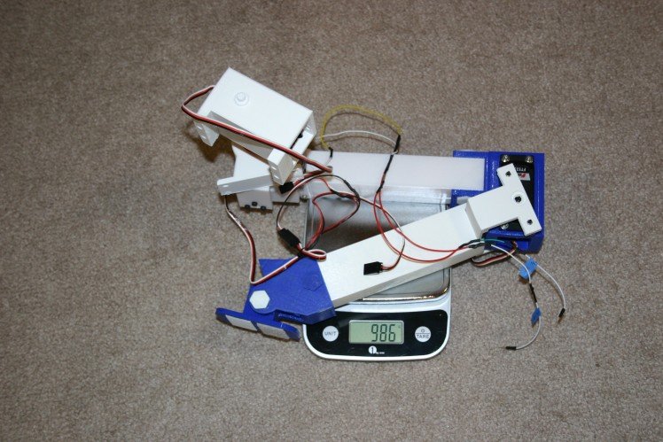
I checked the total leg mass and it came in at 986 grams--which is 86 grams more than the original.
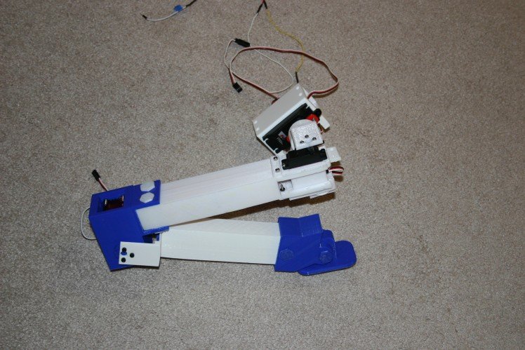
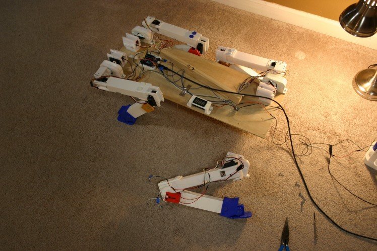
Leg Removal and Upgrade--Part 1
The left rear leg has to come off for new motors (twice the torque) in the shoulder and elbow joints. First, the wires have to be disconnected.
Next, the leg is removed from the body.
The total leg assembly will require design tweaking to keep the weight down and minimize some sharp edges (I don't want to get hurt--the motors are getting pretty powerful now). A good leg assembly could be a "module" for the Robotics Module Challenge.
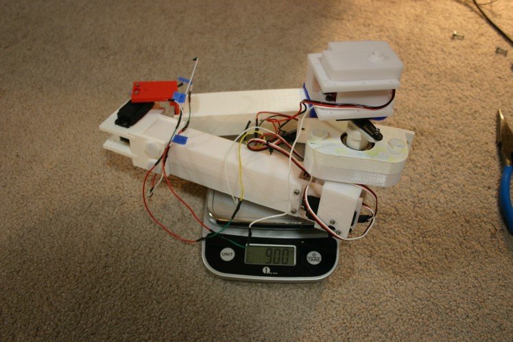
I put the existing leg assembly on the scales and it came in at 900 grams.
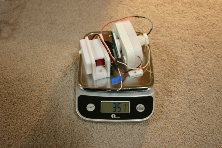
The shoulder motor and bearings (existing) are 351 grams.
The new (larger and heavier motor) shoulder motor and printed bearing comes in at 280 grams.
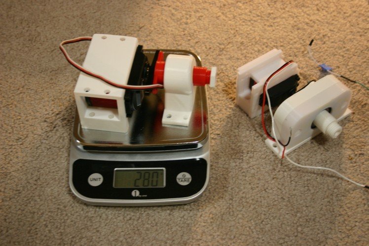
At least it's going in the right direction--I would love to have the new leg weigh the same or less as the old leg.
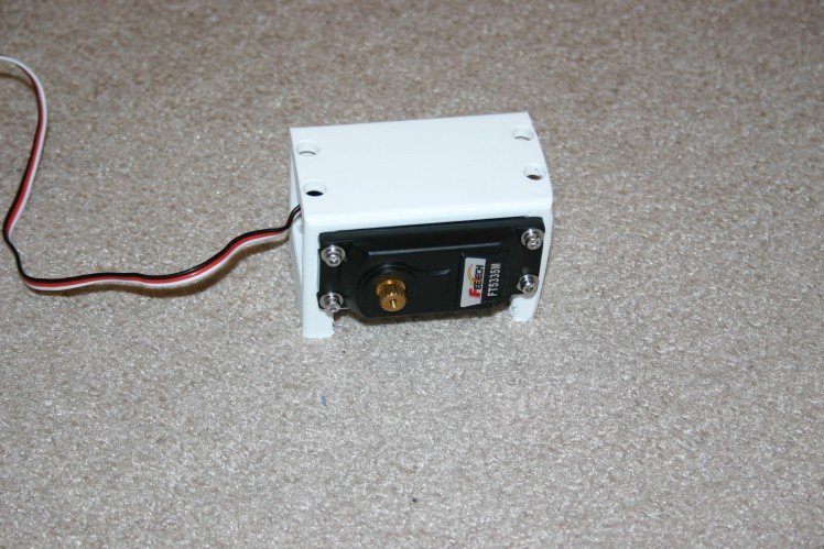
Testing the Large Servo Motor
Before changing the servo motors, I need to know something about the motion limits and power requirements of the large motors (FT 5335 M from Pololu).
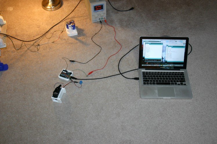
Using an Arduino, any commands lower than 30 degrees do not correspond to movement, thus 30 degrees represents the most clockwise position (viewed from the top).
The 150 degree command is the last one that works in the counter clockwise position, thus I have about 120 degrees available for movement.
At 7.4 volts, two amps minimum is needed to during unloaded motor travel. About .12 amps are required to stay in position with no force applied.
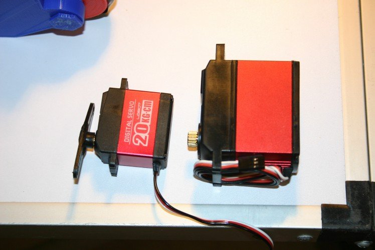
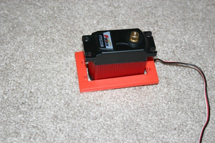
Larger Servo Motor
The dog stands, but just barely. As long as the voltage remains solid, motors don't overheat and all four legs share the lift in a fairly even manner, she will stand.
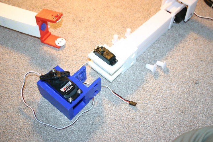
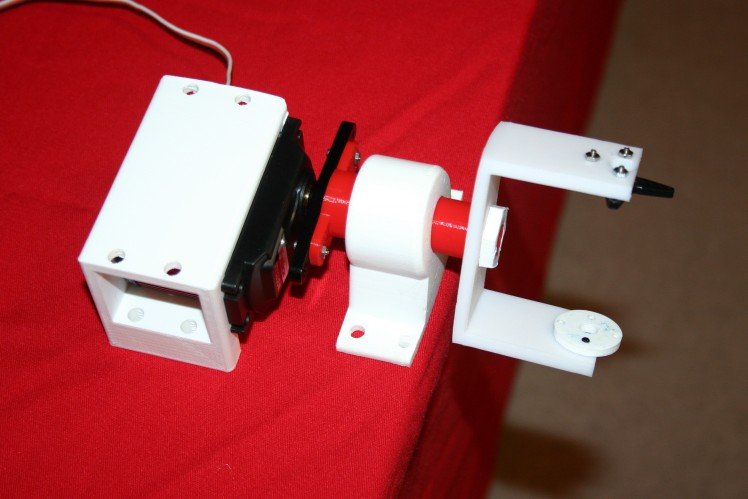
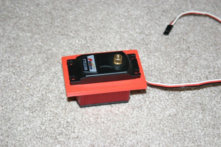
It's time for more torque. I'm trying a larger servo motor (1/4 scale) that provides double the torque of my current motors (550 oz. in versus 277) at slightly more than double the cost ($39.95 each).
Here's what the new motor looks like compared to the old one.
Now, to start the knee change design process. First, I measured the new servo and printed a template to see if the motor and screw holes would align.
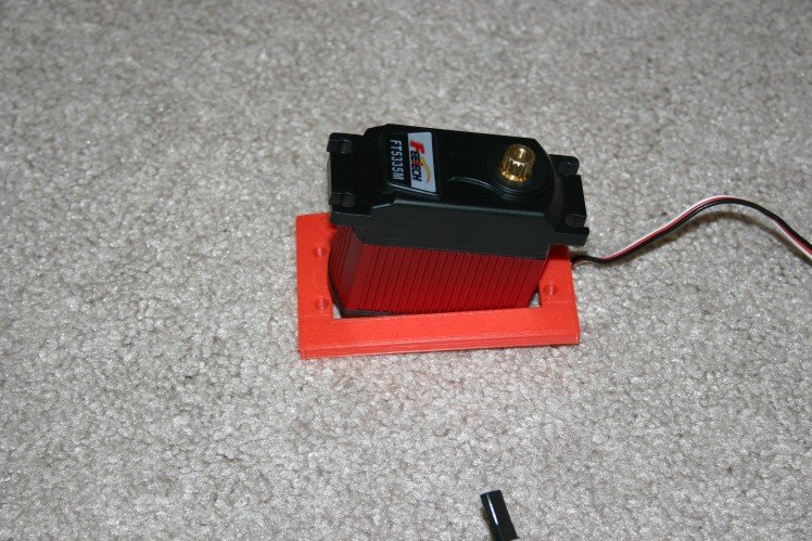
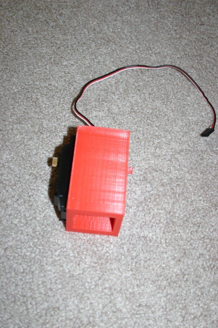
Too precise! The motor has to be "angled in" to fit the cable; thus the length of the slot must be slightly larger than the length of the servo body to work.
Just adding a millimeter here and there resulted in a hole too large. Time to adjust again and reprint the template.
This is a good fit--now to add some depth and sides.
That looks good. Next, it needs to blend with the upper leg attachment bracket.
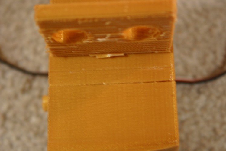
During the 4 1/2 hour print, filament on the spool was tangled and a weak layer was printed in the bracket. Time to change filament and print again.
This looks pretty good.
I think this will work--of course I'll have to create a new receiving bracket for the lower leg.
The Forces Are Not All With Me
My experimental results were confusing, so I needed a better grasp of the forces at work.
The front end of the dog would stand easily enough. The rear end refused--either the feet would slide, the entire dog shift rearward or some other odd combination. Tests indicated that the rear legs could produce the same torque as the front legs, so what was going on?
I decided to assume some experimental circumstances. From the left side, suppose that the left front foot is fixed to the ground and the shoulder is free to rotate. Change the knee angle from 60 degrees to 80 degrees.
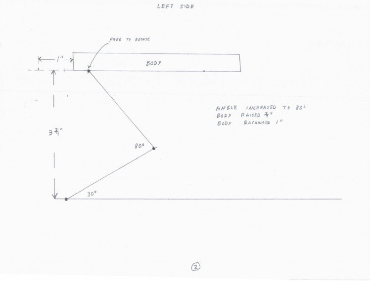
The body should rise and move backward.
Now, same imaginary experiment, but don't let the body move rearward--let the friction of the rear legs or some other force prevent rearward movement.
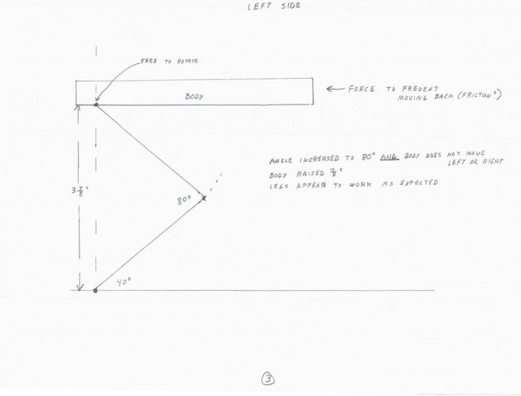
The body rises and the leg "looks" the way I thought it would.
Now, looking at the left side, let's assume the front and rear legs are operational--feet fixed and shoulders free to rotate.
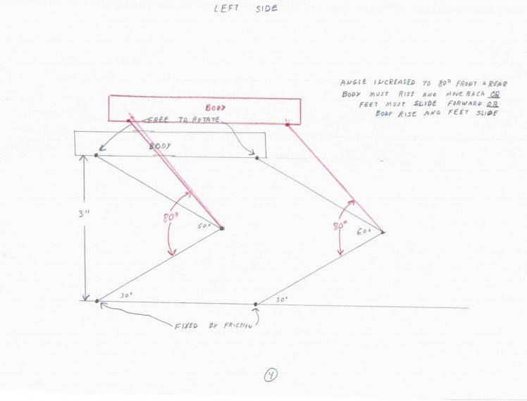
The body must rise and move rearward or the feet must slide forward or some combination.
Now, another thought experiment. From the left side, let's look at the front shoulder joint and assume that the shoulder rotates in the clockwise direction.
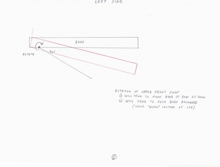
This will tend to make the rear of the body go down and it will tend to push the body backward (think wheel instead of leg and the "foot" (wheel) does not slide).
What happens when the rear shoulder joint turns clockwise?
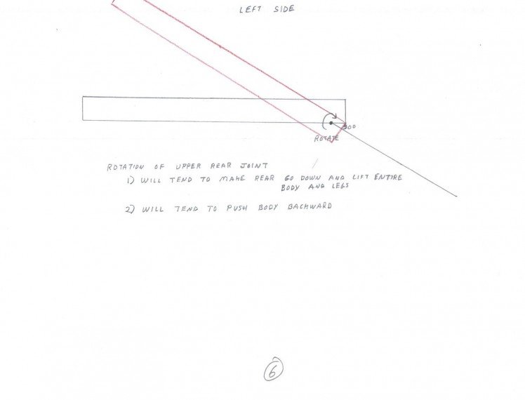
This will tend to make the rear go down and the front rise up while pushing the body rearward.
Everything seems to push the body backward and a couple of things work to push the rear end toward the ground.
Now, I'm pulling out my ace--in 1999 I purchased a Sony robot dog, Aibo.
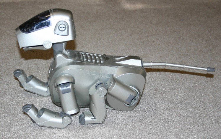
To stand, Aibo's left front shoulder turns clockwise and his left rear shoulder turns counterclockwise.
I flipped the rear legs on my dog (right rear became left rear; left rear became right rear) and he was able to stand.
This doesn't explain how Boston Dynamics gets their dog to stand--but that's not my problem. Note in the "Details" that the "Anymal" dog uses the opposing rotation method.
For general information, while tearing my dog apart I noted that a leg assembly (including three 67 gram motors and two steel bearings) comes in at 808 grams. I need to reduce this in a redesign--just another thing to keep in mind.
Torque Damage and Sitting
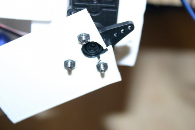
The right rear leg quit--I figured a motor was cooked, but the problem turned out to be a stripped out plastic servo horn (note the bits of black plastic on the table).
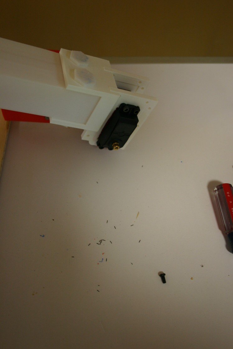
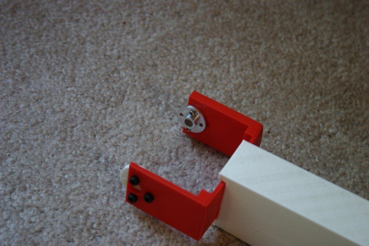
I pulled the leg off to remove the old plastic horn.
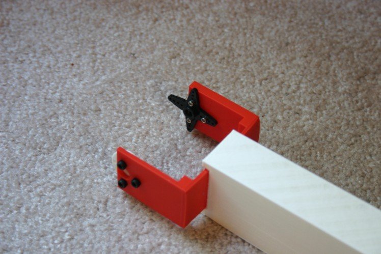
The new aluminum horn fits the servo motor, but it's a bit dicey attaching the new horn to the 3d printed leg joint. It kind of works, but I'll have to redesign the joint and rework all the legs.
Changing two of these servo horns allowed enough control that I could attempt a sitting position.
Testing Servo Motor Torque
The servo motors I am currently using claim to have a torque rating of 20 kg-cm (277.6 oz-in). Rather than just accepting an advertised claim, I thought it would be a good idea to know if the motor could really produce such torque.
My test rig involves a 1" x 2" pine board attached to a servo motor. At a distance of 21" from the servo shaft, I have taped 8.3 ounces of lead weight. Twenty-one inches multiplied by 8.3 ounces yields 174.3 ounce-inches of torque. The 8 ounce wood arm (assuming even distribution and that the center is 11 inches from the arm) contributes 88 ounce inches to the torque required. Adding 174.3 to 88 yields 262.3 ounce inches of torque. I didn't play with weights to find the absolute max, but I have no reason to question the 277.6 oz-in advertised.
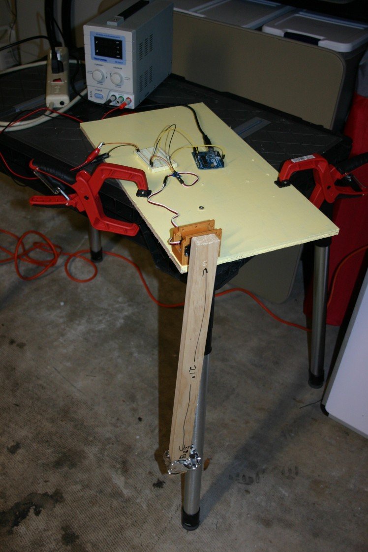
Under load, it looks like this:
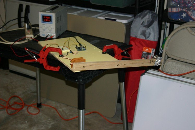
As an interesting side note, the current required to hold the arm horizontally (at 7 volts) is about .4 amps. If the current limit on the power supply is less than 2.5 amps, the servo motor won't rotate the arm.
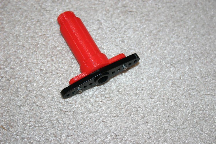
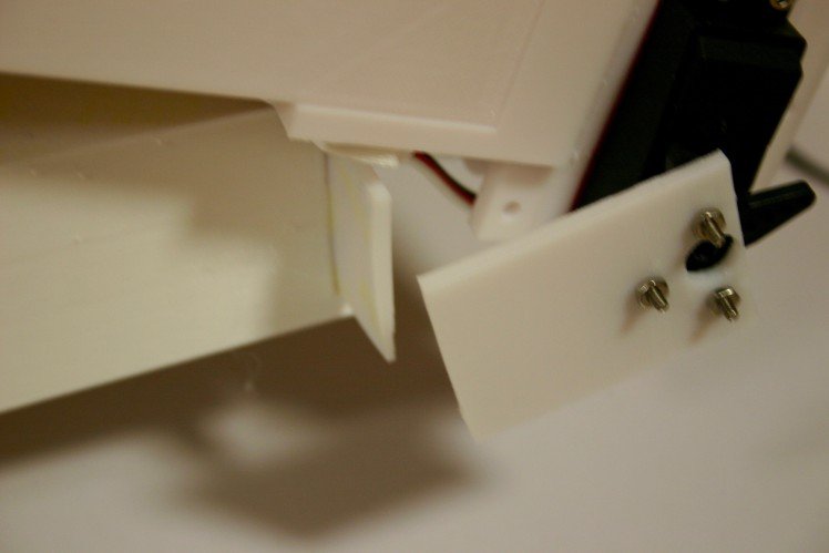
Repair Broken Joint and Stop Slipping
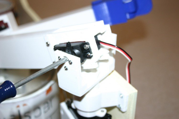
I printed a stronger joint piece and replaced the broken and damaged joints.
This photo shows the replacement of the "back bearing" for the servo motor.
 This is the installation of the servo horn.
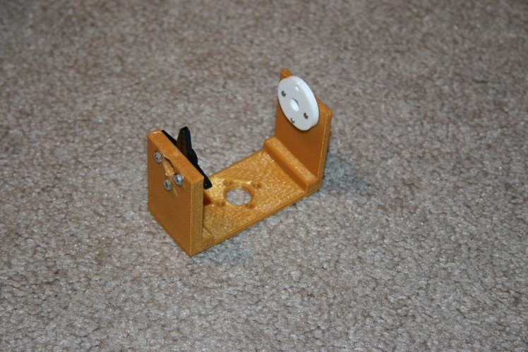
This is the attachment of the servo piece to the leg.
The servo attachment piece has to be fastened to the servo motor using the servo screw.
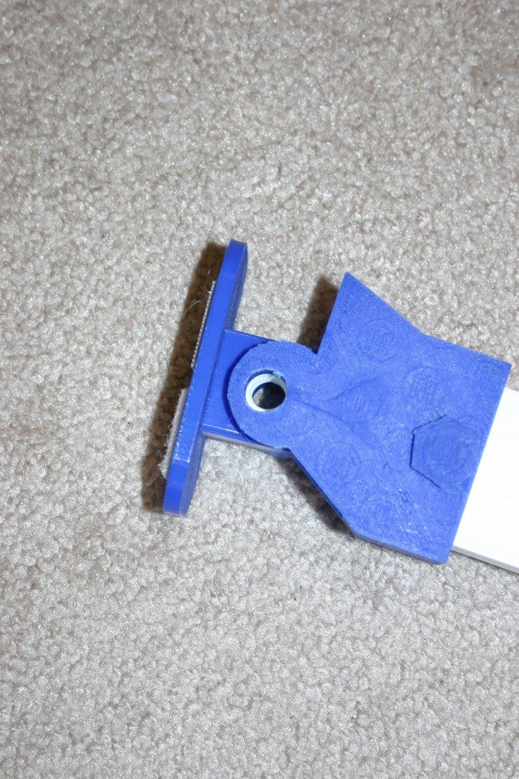
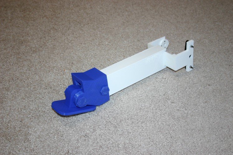
Next, I made a wider wheel, one that will not turn, to be in the foot position. Part of my trouble with standing involved the foot "moving around" instead of the body lifting.
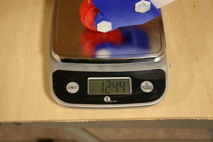
For test purposes, I clamped the body to the "hanging support" so that the body could not be lifted.
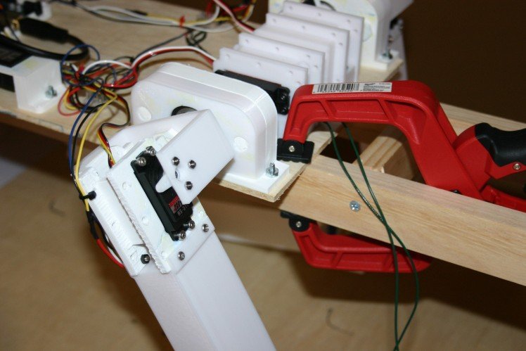
Next, I "asked" the leg to push as hard as possible. The result was 1.24 kilograms. At least under some circumstances, four legs working together should be able to lift about 5 kilograms. The body is about 1.5 kilograms, so there should be enough push to get off the ground.
I probably need some feedback and better software, but things are progressing.
First Stand
On February 27, the first attempt at standing was made. A couple of the joints couldn't take full speed movement--we learn by trying!
To attempt the first standing test, I needed to determine the servo angles for each motor. Below is the schematic for the system.
With the mechanism suspended, I determined the servo angles for each servo.

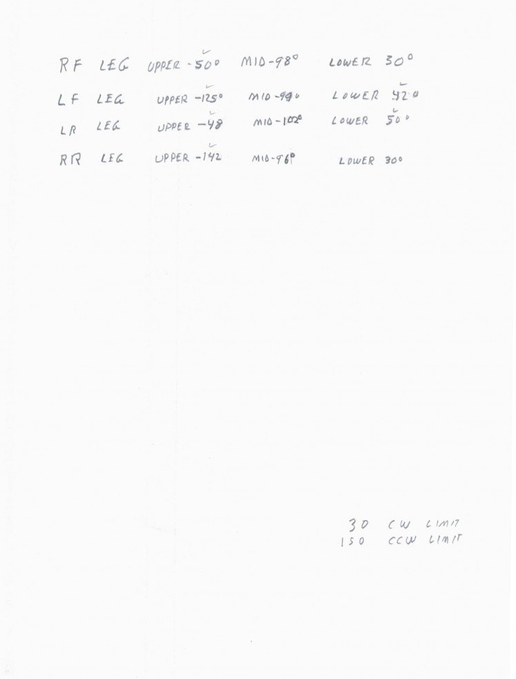
The numbers I retrieved are:
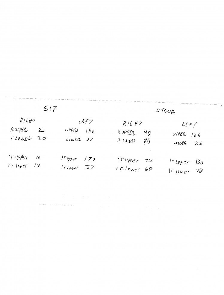
I applied those in an Arduino sketch (found in files on this project).
Two joints couldn't take the stress (I went full speed on the servos, kind of a worst case situation).
I'll have to redesign and install joints--then full torque ahead!
Credits
Related products


Leave your feedback...