

Attiny85 Clock With Tap Tempo

About the project
A simple clock with tap tempo made with an ATTiny85 board, useful for eurorack systems
Items used in this project
Hardware components

Story
ATTiny85 Clock with tap tempo function
A simple clock with tap tempo made with an ATTiny85 board, useful for eurorack systems.
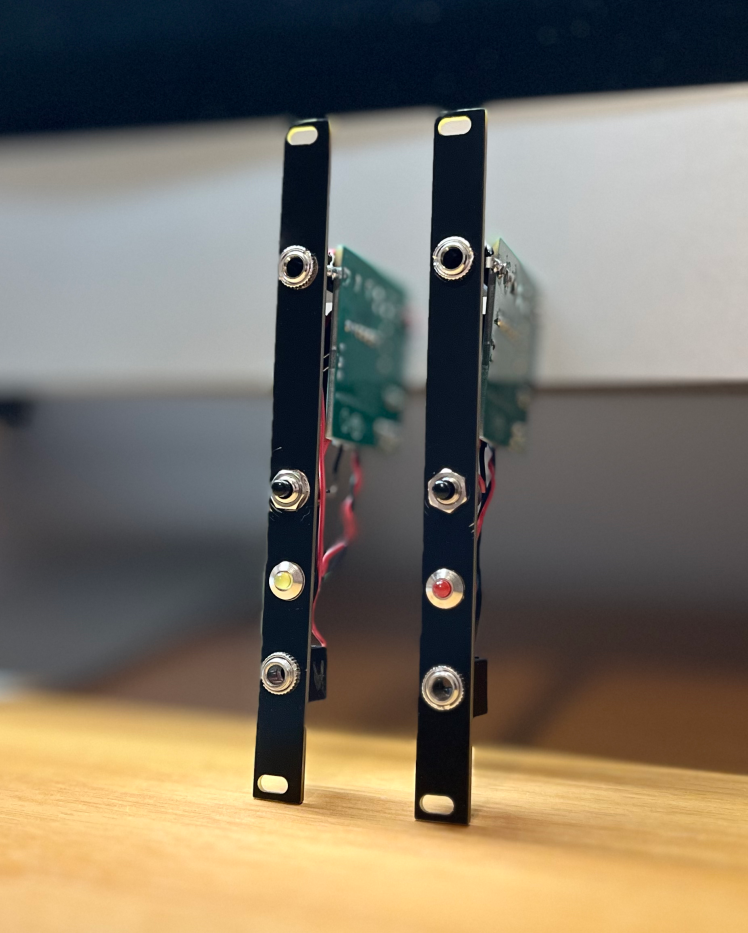
This is the cheapest (less than 5 euros in components) and smallest (building it with the PCB can be mounted in a 2HP panel) clock module ever made.
I always wanted a simple clock module with a Tap Tempo feature but the cheapest one is about 40-50 euros.
Furthermore, I couldn't find an already made simple DIY project for that.
I had some ATTinys boards laying around and since their application is very limited (they are really simple boards that can be seen as Arduinos to the lower terms) I tried to design a module as simple as it can be.
The module features two clock outputs (a main one and an aux one) a status LED and a simple momentary NO button for the tap function. It's not perfect, but the part count is really low, which makes it really cheap while still doing the job.
Demo video: https://youtube.com/shorts/PZ5HyXFXe1c
Features:
- BPM from 5 to 400 (can be edited in the code)
- One clock output and one auxiliary output
- Status LED
- Tap Tempo
BOM
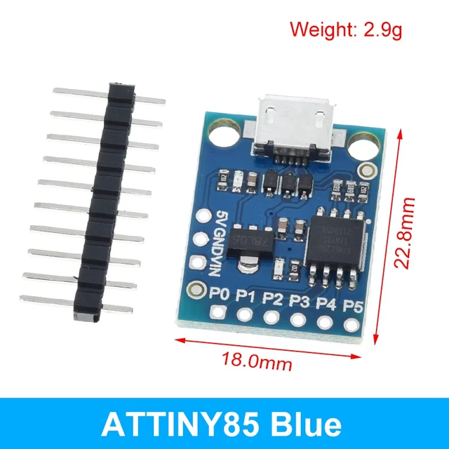
- ATTiny85 board (this blue one from the famous oriental marketplace if you want to make the module with the attached PCB, the board should have no "ATTINY85" written near the P0 pin)
- 1 x 100 uF capacitor
- 3 x 1KΩ resistors
- 1 x 10 pin (2x5) 2.54mm IDC header
- 1 x 3mm LED (you can use a 5mm one as well)
- 1 x NO momentary switch
- 1 x 3.5mm female jack
- 1 x 3.5mm female jack PJ-316M (OPTIONAL, if you want to use the in-board jack)
Solder everything as reported in the schematic, upload the sketch through the Arduino IDE and enjoy!
You can upload the Gerber zip to your favourite PCB supplier and make your own just by ordering them.
DISCLAIMER
The circuit is not perfect, it's as simple as it can be: it uses the onboard voltage regulator (the 78L05 which has 7-30V input range) there's no polarity protection and the switch is not debouncing well sometimes, but you know, it's DIY and really cheap and still does the job :D
Schematics, diagrams and documents
CAD, enclosures and custom parts
Code
Credits
Related products


Leave your feedback...