

Measure Motor Speed (rpm) With Optocoupler And Encoder Disk

About the project
Measure rotation speed (RPM) with Optocoupler and Encoder disk and Arduino - Quick and Easy!
Project info
Difficulty: Easy
Estimated time: 1 hour
License: GNU General Public License, version 3 or later (GPL3+)
Items used in this project

Software apps and online services
Story
When building a robot car, it is important to control the speed of the rotation of the wheels. Before we can control the speed however, we need to be able to measure it. One of the easiest and most popular ways of measuring the speed is with Optocoupler, and Encoder Wheel. Most of the Smart Car kits come with Encoder Wheels included, and I already made Tutorial on how to connect Optocoupler to Arduino. Now I will show you how you can use the Optocoupler to measure the rotation speed of the wheel.
Step 1: Components
1 / 3 • Picture 1

Picture 1

Picture 2

Picture 3
- One Arduino compatible board (I use Arduino Nano, because I have one, but any other will be just fine)
- One Optocoupler module with LM393 comparator with digital output (Picture 2)
- One Smart Car chassis with at least one DC motor, and rotary encoder wheel (Picture 3)
- 3 Female-Female jumper wires
1 / 5 • Picture 1

Picture 1

Picture 2

Picture 3

Picture 4

Picture 5
- Connect Power (Red wire), and Ground (Black wire) to the Optocoupler Module (Picture 1 and 2)
- Connect Data (Gray wire) to the digital pin of the Optocoupler Module (Picture 1 and 2)
- Connect the other end of the Ground wire (Black wire) to Ground pin of the Arduino board (Picture 3)
- Connect the other end of the Power wire (Red wire) to the 5V power pin of the Arduino board (Picture 3)
- Connect the other end of the Data wire (Gray wire) to Digital pin 2 of the Arduino board (Picture 4)
- Picture 5 shows where are the Ground, 5V Power, and Digital 2 pins of the Arduino Nano.
1 / 3 • Picture 1

Picture 1

Picture 2

Picture 3
Mount the Optocoupler on the Smart Car so the Encoder Wheel will be inserted in the slot of the Optocoupler (Pictures 1, 2 and 3)
Step 4: Start Visuino, and select the Arduino Board type
1 / 2 • Picture 1

Picture 1

Picture 2
To start programming the Arduino, you will need to have the Arduino IDE installed from here: http://www.arduino.cc/.
Please be aware that there are some critical bugs in Arduino IDE 1.6.6.
Make sure that you install 1.6.7 or higher, otherwise this Tutorial will not work!
The Visuino: https://www.visuino.com also needs to be installed.
- Start Visuino as shown in the first picture
- Click on the "Tools" button on the Arduino component (Picture 1) in Visuino
- When the dialog appears, select Arduino Nano as shown in Picture 2
1 / 3 • Picture 1

Picture 1

Picture 2

Picture 3
- Type "freq" in the Filter box of the Component Toolbox then select the "Frequency Meter" component (Picture 1), and drop it in the design area
- Connect the "Out" output pin of the Digital[ 2 ] channel of the Arduino component to the "In" input pin of the FrequencyMeter1 component (Picture 2)
- Connect the "Out" output pin of the FrequencyMeter1 component to the "In" input pin of the Serial[ 0 ] channel of the Arduino component (Picture 3)
1 / 2 • Picture 1

Picture 1

Picture 2
- In Visuino, Press F9 or click on the button shown on Picture 1 to generate the Arduino code, and open the Arduino IDE
- In the Arduino IDE, click on the Upload button, to compile and upload the code (Picture 2)
1 / 5 • Picture 1

Picture 1

Picture 2

Picture 3

Picture 4

Picture 5
On Picture 1 you can see the completed and powered project.
- In Visuino select the Serial Port and click the Connect button (Picture 3)
- In the Serial Terminal you will see the distance measured by the sensor (Picture 4)
- If you click on the Scope Tab you can also see the values plotted in the Scope (Picture 5)
Congratulations! You have learned how to measure the speed of the motor rotation with Optocoupler and Encoder wheel.
On Picture 2 you can see the complete Visuino diagram.
Since the encoder wheel has multiple holes it generates multiple pulses per rotation. My wheel has 20 holes, so it generates 20 pulses. To properly convert the result to RPM (Revolutions Per Minute) you will need to divide the measured value by 20. Look at the next Step to see how to do this.
Step 8: In Visuino: Add and connect Divide By Value component
1 / 5 • Picture 1

Picture 1

Picture 2

Picture 3

Picture 4

Picture 5
- Right click over the connection between the "Out" pin of the FrequencyMeter1 component and the Serial Port (Picture 1)
- From the menu select the "Disconnect link" to disconnect the "Out" pin of the FrequencyMeter1 component (Picture 1)
- Type "divid" in the Filter box of the Component Toolbox then select the "Divide By Value" component (Picture 2), and drop it in the design area
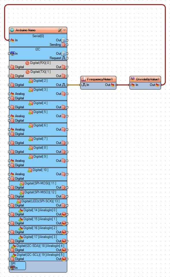
- Connect the "Out" output pin of the FrequencyMeter1 component to the "In" input pin of the DivideByValue1 component (Picture 3)
- Connect the "Out" output pin of the DivideByValue1 component to the "In" input pin of the Serial[ 0 ] channel of the Arduino component (Picture 4)
- In the Object Inspector set the value of the "Value" property to "20" (Picture 5)
- Generate, Compile, and Upload the Arduino code as you did in Step 6
- If you power the project and connect to Arduino over the serial port, as you did in Step 7, you will see the speed displayed in RPM
Congratulations! You have learned how to measure the speed of the motor, and convert it to RPM (Revolutions Per Minute).
The Picture shows the complete Visuino diagram. On the video you can see the running project before the Divide By Value is added. The final project looks and works the same way, except the displayed values will be divided by 20.
Also attached is the Visuino project, that I created for this Tutorial. You can download and open it in Visuino: https://www.visuino.com
Credits
Related products


Leave your feedback...