

Max30100 Sensor - How To Use Custom Code In Visuino Pro

About the project
In this tutorial we are going to learn how to use a Custom Code component in Visuino Pro, that allows us to add any Arduino code.
Project info
Difficulty: Difficult
Estimated time: 1 hour
License: GNU General Public License, version 3 or later (GPL3+)
Items used in this project
Hardware components

Story
In this tutorial we are going to use the MAX30100 Heart Rate Sensor & Oximeter to read the hear beat & oxygen level and display the results in the serial monitor or on the ST7735 Display.
Custom Code component in Visuino Pro is very useful if you need to add some sensor that is not yet supported in Visuino but you already have the code for it, or to just experimenting by adding your own code to the project.
Custom code in Visuino PRO is solving nearly 100% of all the missing functionality in Visuino Standard version.
More about Visuino Pro here
Here are also some very good tutorials on how to use a Custom Code component:
Getting started with the Custom Code component
Step 1: What You Will Need1 / 7
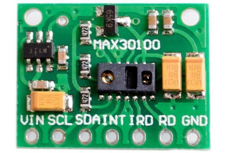
- MAX30100 sensor
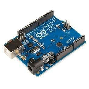
- Arduino UNO
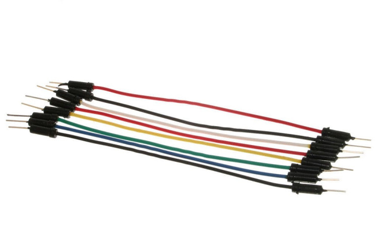
- Jumper wires
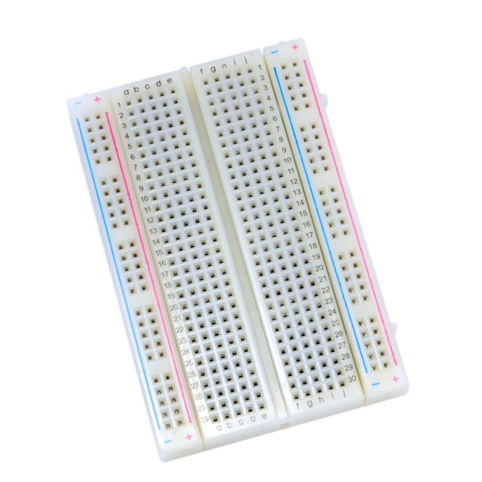
- Breadboard
- Visuino Pro software: Download here
Optional:
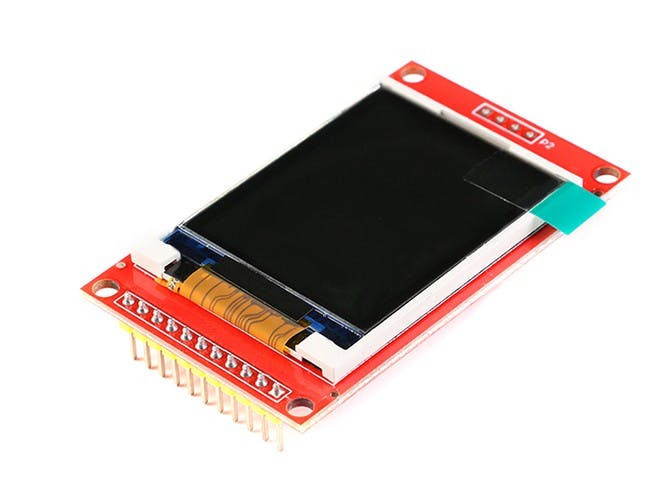
- ST7735 Display
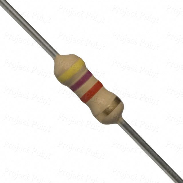
- 2X Resistor 4.7K ohm
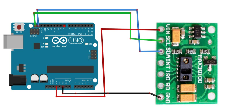
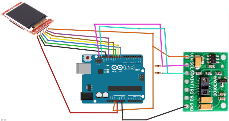
- Connect MAX30100 Sensor pin [SCL] to Arduino pin [SCL]
- Connect MAX30100 Sensor pin [SDA] to Arduino pin [SDA]
- Connect MAX30100 Sensor pin [VCC] to the breadboard positive pin [3.3V]
- Connect MAX30100 Sensor pin [GND] to the breadboard pin [GND]
- Connect MAX30100 Sensor pin [SCL] to Arduino pin [SCL]
- Connect MAX30100 Sensor pin [SDA] to Arduino pin [SDA]
- Connect MAX30100 Sensor pin [VCC] to the breadboard positive pin [3.3V]
- Connect MAX30100 Sensor pin [GND] to the breadboard pin [GND]
- Connect MAX30100 Sensor pin [SDA] to 4.7k Resistor and other side of the Resistor to Arduino 3.3V pin
- Connect MAX30100 Sensor pin [SCL] to 4.7k Resistor and other side of the Resistor to Arduino 3.3V pin
- Connect ST7735 Display PIN [LED] to Arduino PIN [3.3 V]
- Connect ST7735 Display PIN [SCK] to Arduino PIN [13]
- Connect ST7735 Display PIN [SDA] to Arduino PIN [11]
- Connect ST7735 Display PIN [A0 or DC] to Arduino PIN [9]
- Connect ST7735 DisplayPIN [RESET] to Arduino PIN [8]
- Connect ST7735 Display PIN [CS] to Arduino PIN [10]
- Connect ST7735 Display PIN [GND] to Arduino PIN [GND]
- Connect ST7735 Display PIN [VCC] to Arduino PIN [5V]
NOTE: Some Arduino boards have different SPI pins so make sure you check your board documentation.
Step 4: MAX30100 Arduino Code & Library1 / 4
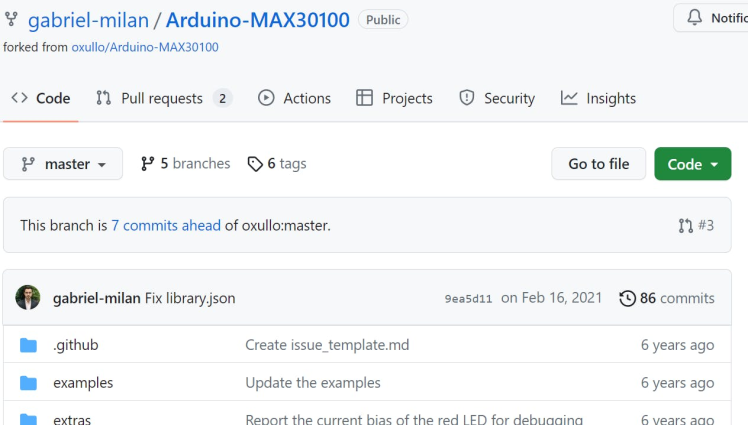
Go to https://github.com/gabriel-milan/Arduino-MAX30100 and download
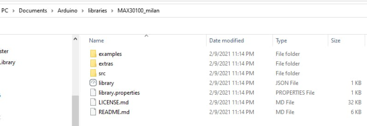
Extract the to your Arduino Libraries folder, usually it looks something like this: C:UsersUserDocumentsArduinolibraries
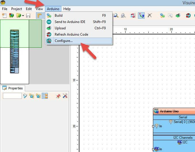
You can also find the Path if you in Visuino click on the Menu>Arduino>Configure and see it under "Arduino Library Directory" (see attached screenshot)
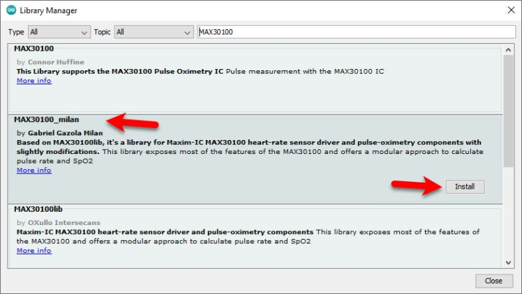
Or in Arduino IDE click on the menu "Sketch" > "Include Library" > "Manage Libraries" and search for "Max30100_milan" and Install this library.
Step 5: Start Visuino Pro, and Select the Arduino UNO Board Type1 / 2
The Visuino Pro: https://www.visuino.eu also needs to be installed. Download Free version or register for a Free Trial.
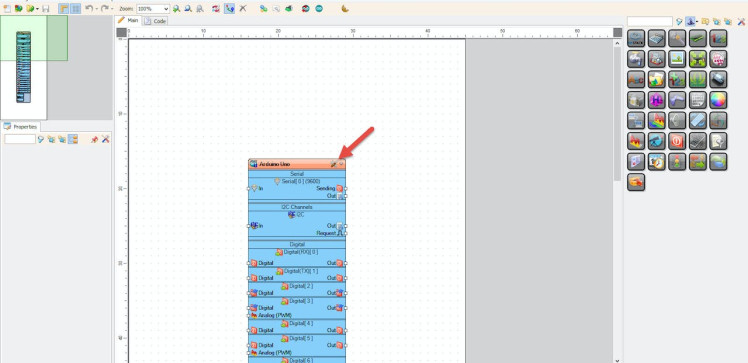
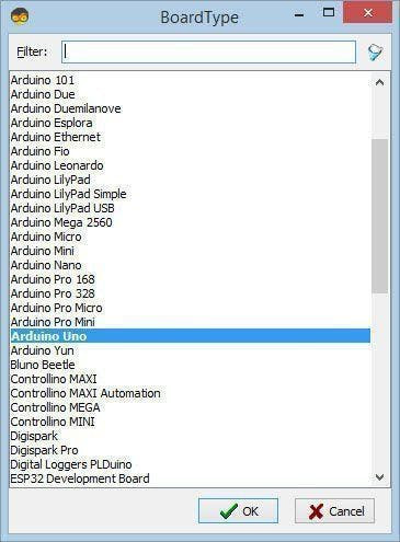
Start Visuino as shown in the first picture Click on the "Tools" button on the Arduino component (Picture 1) in Visuino When the dialog appears, select "Arduino UNO" as shown on Picture 2
Step 6: In Visuino Add Components1 / 3
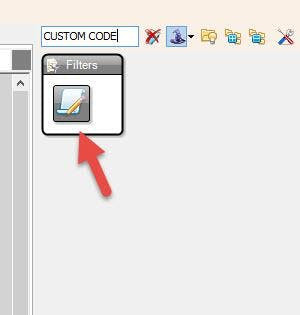
- Add "Custom Code" component
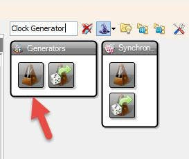
- Add "Clock Generator" component
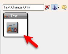
- Add 2X "Text Change Only" component (We are adding this components so that the text will be updated only when the values change )
1 / 2
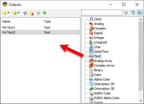
- Double click on the "CustomCode1" and in the "Outputs" window drag 2X "Text" to the left side and close the "Outputs" window
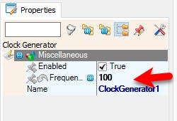
- Select "ClockGenerator1" and in the properties window set "Frequency" to 100 (we are setting this Frequency to 100Hz because the original code suggests that we should update the Data as fast as possible)
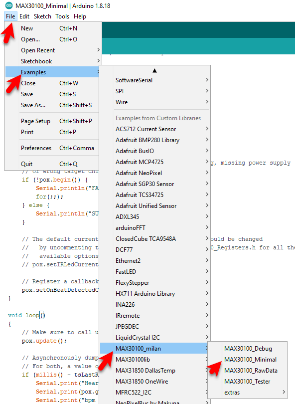
The code that we will use in our project is located under the Examples > MAX30100_milan > MAX30100_Minimal
/*
Arduino-MAX30100 oximetry / heart rate integrated sensor library
Copyright (C) 2016  OXullo Intersecans <x@brainrapers.org>


This program is free software: you can redistribute it and/or modify
it under the terms of the GNU General Public License as published by
the Free Software Foundation, either version 3 of the License, or
(at your option) any later version.


This program is distributed in the hope that it will be useful,
but WITHOUT ANY WARRANTY; without even the implied warranty of
MERCHANTABILITY or FITNESS FOR A PARTICULAR PURPOSE.  See the
GNU General Public License for more details.


You should have received a copy of the GNU General Public License
along with this program.  If not, see <http://www.gnu.org/licenses/>.
*/


#include <Wire.h>
#include "MAX30100_PulseOximeter.h"


#define REPORTING_PERIOD_MS     1000


// PulseOximeter is the higher level interface to the sensor
// it offers:
//  * beat detection reporting
//  * heart rate calculation
//  * SpO2 (oxidation level) calculation
PulseOximeter pox;


uint32_t tsLastReport = 0;


// Callback (registered below) fired when a pulse is detected
void onBeatDetected()
{
    Serial.println("Beat!");
}


void setup()
{
    Serial.begin(115200);


    Serial.print("Initializing pulse oximeter..");


    // Initialize the PulseOximeter instance
    // Failures are generally due to an improper I2C wiring, missing power supply
    // or wrong target chip
    if (!pox.begin()) {
        Serial.println("FAILED");
        for(;;);
    } else {
        Serial.println("SUCCESS");
    }


    // The default current for the IR LED is 50mA and it could be changed
    //   by uncommenting the following line. Check MAX30100_Registers.h for all the
    //   available options.
    // pox.setIRLedCurrent(MAX30100_LED_CURR_7_6MA);


    // Register a callback for the beat detection
    pox.setOnBeatDetectedCallback(onBeatDetected);
}


void loop()
{
    // Make sure to call update as fast as possible
    pox.update();


    // Asynchronously dump heart rate and oxidation levels to the serial
    // For both, a value of 0 means "invalid"
    if (millis() - tsLastReport > REPORTING_PERIOD_MS) {
        Serial.print("Heart rate:");
        Serial.print(pox.getHeartRate());
        Serial.print("bpm / SpO2:");
        Serial.print(pox.getSpO2());
        Serial.println("%");


        tsLastReport = millis();
    }
}
1 / 10
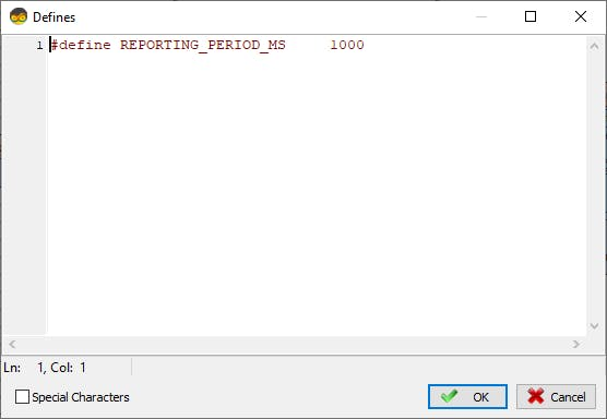

Select "CustomCode1" and in the properties window select "Defines" and Click on the 3dots button
In the "Defines" window add this code:
#define REPORTING_PERIOD_MS 1000And Close the "Defines" window
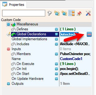
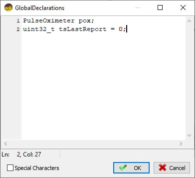
Select "CustomCode1" and in the properties window select "Global Declarations" and Click on the 3dots buttonIn the "Global Declarations" window add this code:
PulseOximeter pox;
uint32_t tsLastReport = 0;
And Close the "Global Declarations" window
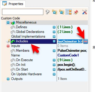
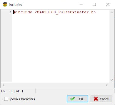
In the "Includes" window add this code:
#include <MAX30100_PulseOximeter.h>And Close the "Includes" window
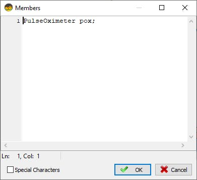
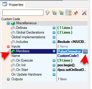
Select "CustomCode1" and in the properties window select "Members" and Click on the 3dots button
In the "Members" window add this code:
PulseOximeter pox;And Close the "Members" window
Select "CustomCode1" and in the properties window select "On Execute" and Click on the 3dots button
In the "On Execute" window add this code:
{
       pox.update();
       Text1.Send(String(pox.getHeartRate()));
       Text2.Send(String(pox.getSpO2()));
}
And Close the "On Execute" window
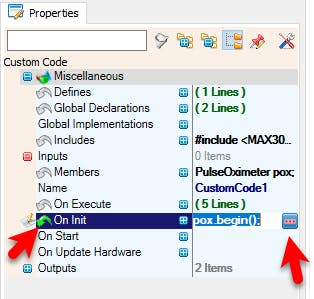
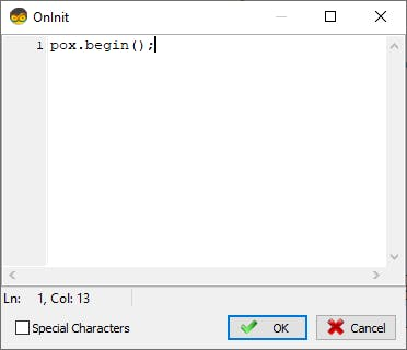
Select "CustomCode1" and in the properties window select "On Init" and Click on the 3dots button
In the "On Init" window add this code:
pox.begin();And Close the "On Init" window
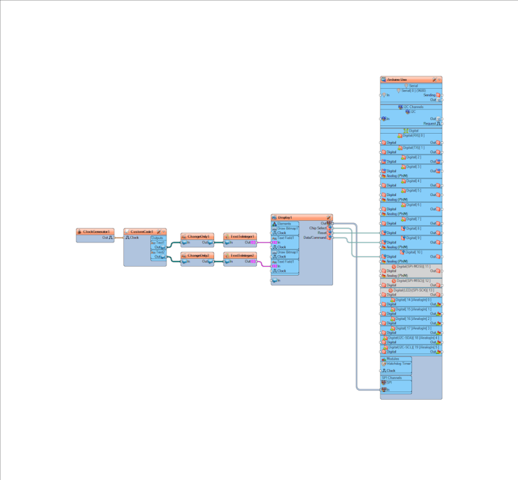
Step 10: In Visuino Connect Components1 / 2
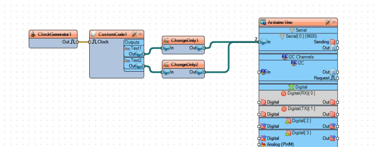
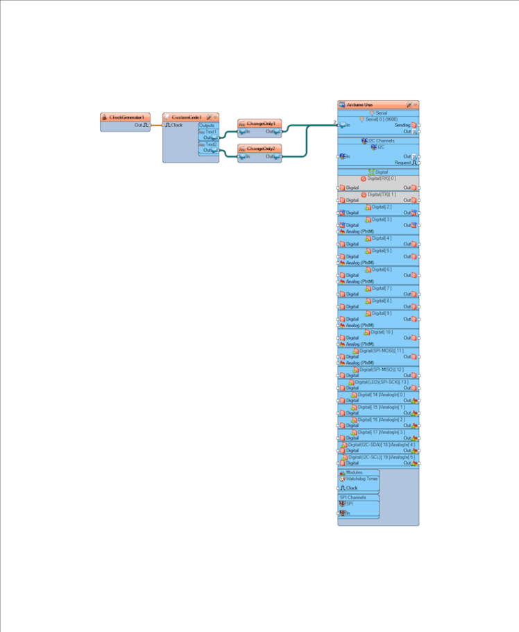
- Connect "ClockGenerator1" pin [Out] to "CustomCode1" pin [Clock]
- Connect "CustomCode1" > "Text1" pin [Out] to "ChangeOnly1" pin [In]
- Connect "CustomCode1" > "Text2" pin [Out] to "ChangeOnly2" pin [In]
- Connect "ChangeOnly1" pin [Out] to "Arduino" pin Serial pin [In]
- Connect "ChangeOnly2" pin [Out] to "Arduino" pin Serial pin [In]
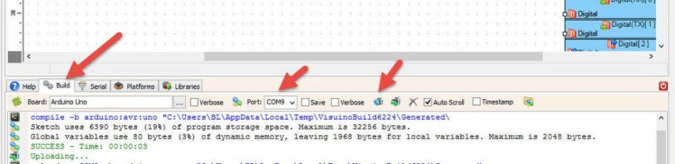
In Visuino, at the bottom click on the "Build" Tab, make sure the correct port is selected, then click on the "Compile/Build and Upload" button.
Step 12: Reading the Data1 / 2
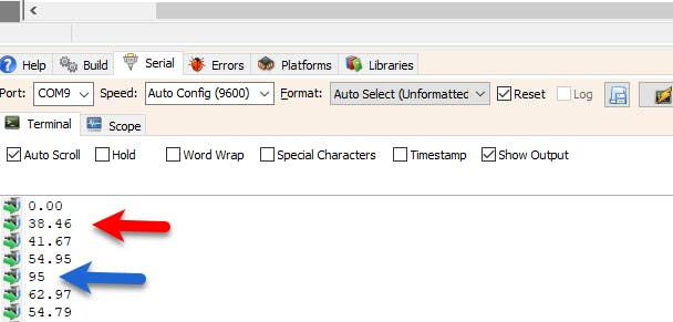
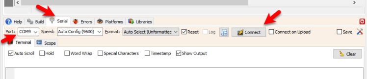
- Upload the project (see the step Generate, Compile, And Upload The Arduino Code) and in Visuino select "Serial" tab, select the Port and click "Connect" button.
- Once connected put the finger on the Sensor and shortly you should see the Heart Pulse and Blood Oxygen level (See the attached picture)
1 / 11
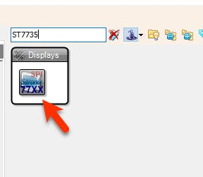


- Add to the project "ST7735" Display component
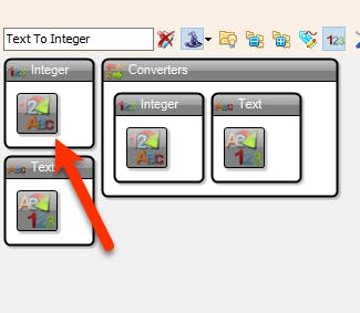
- Add 2X "Text To Integer" component (we will use this component to remove the decimal values)
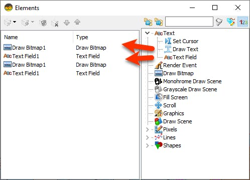
- Double click on the "Display1" component and in the Elements window:
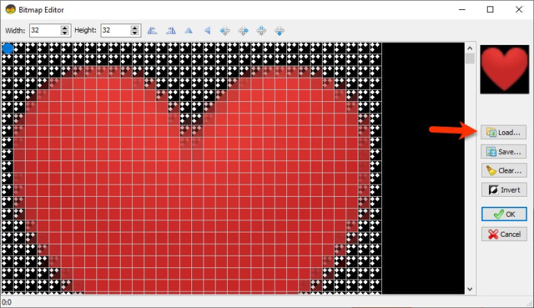
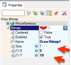
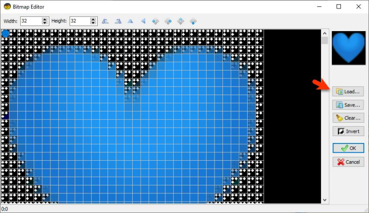
- Drag "Draw Bitmap" to the left side and in the properties window set "X" to 5 and "Y" to 10 and click on the "Bitmap" 3 dots button and in the Bitmap Editor window load the bitmap (Red Heart) and close the Bitmap Editor window
- Drag "Text Field" to the left side and in the properties window set "Size" to 3, "X" to 70 and "Y" to 20
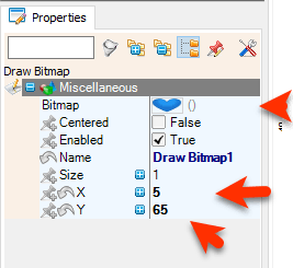
- Drag "Draw Bitmap" to the left side and in the properties window set "X" to 5 and "Y" to 65 and click on the "Bitmap" 3 dots button and in the Bitmap Editor window load the bitmap (Blue Heart) and close the Bitmap Editor window
- Drag "Text Field" to the left side and in the properties window set "Size" to 3, "X" to 70 and "Y" to 75
- Close the Elements window
Note: Heart Bitmaps are attached
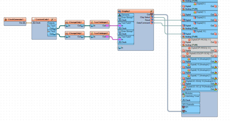
- Connect "ClockGenerator1" pin [Out] to "CustomCode1" pin [Clock]
- Connect "CustomCode1" > "Text1" pin [Out] to "ChangeOnly1" pin [In]
- Connect "CustomCode1" > "Text2" pin [Out] to "ChangeOnly2" pin [In]
- Connect "ChangeOnly1" pin [Out] to "TextToInteger1" pin [In]
- Connect "ChangeOnly2" pin [Out] to "TextToInteger2" pin [In]
- Connect "TextToInteger1" pin [Out] to "Display1" > "Text Field1" pin [In]
- Connect "TextToInteger2" pin [Out] to "Display1" > "Text Field2" pin [In]
- Connect "Display1" component Pin [Out]SPI to Arduino Pin SPI[In]
- Connect "Display1" component Pin [ChipSelect] to Arduino Digital Pin [10]
- Connect "Display1" component Pin [Reset] to Arduino Digital Pin [8]
- Connect "Display1" component Pin [Register Select] to Arduino Digital Pin [9]
Congratulations! You have completed your project with Visuino. Also attached is the Visuino project, that I created for this tutorial, you can download it and open it in Visuino: https://www.visuino.eu
Schematics, diagrams and documents
Code
Credits
Related products


Leave your feedback...