
Mapping The Outdoors With Adafruit. Io And A Notecard

Made by IVM512 / Communication / Garden / Notifications / Wearables / IoT
About the project
Learn how to use Adafruit. io, GPS, and a Blues Wireless Wi-Fi Notecard to map an outdoor space.
Project info
Difficulty: Easy
Platforms: Adafruit, Blues Wireless
Estimated time: 4 hours
License: GNU General Public License, version 3 or later (GPL3+)
Items used in this project
Hardware components

View all
Story
Not all locations are the same in the eyes of a cellular network. That is the case for my home address, because although I do get reception, it's sporadic and often unreliable. In order to track my lawn mower service (me and my reliable push mower), I needed a system that could capture geospatial data, reliably give me signal to cover my property area, transmit data to a cloud service, and display the data on a dashboard.

The challenge was that Wi-Fi would not have the enough strength to reach the limit of the property (even for a small one like mine), and with not ideal conditions cellular was also out of the question. I therefore decided to use a packet radio transceiver that would give me the coverage needed without having to go down the path of LoRa, SigFox or cellular. Using a RFM69 support board at 915Mhz I was able to create a client and server that would manage the transmission locally of the geospatial data.
The Blues Wireless WiFi Notecard gave me the ability to quickly connect the Adafruit feather standard footprint to my network using the Blues Notecarrier AF board. It also allowed me to transmit the data to my preferred cloud service to display on a custom dashboard.
The process was highly educational, easy (as much as can be expected), fast, and satisfactory to see a real-time map of my location as I was mowing the grass.
I hope you find the project interesting and useful, and maybe you can adapt it to your own needs. Enjoy!
MaterialsThe following are the materials used on the project. I know we have them described above, but I always find useful to have a snapshot of the actual elements used.
1 / 8 • Blues Wireless Wi-Fi Notecard

Blues Wireless Wi-Fi Notecard

Blues Wireless Notecarrier AF

Feather M0 RFM69HCW

Feather Wing Ultimate GPS

Active GPS Antenna

Feather Wing Doubler

Feather Wing OLED

Feather M0 Adalogger
Blues WirelessBlues Wireless is an IoT startup that has taken the mobile communication of small devices to an affordable price range for fast prototyping, testing and deployment. An all-in-one solution from MCU boards (Swan), communication (cellular or Wi-Fi), to data collection (Notehub) and integration with the most popular cloud (AWS, Azure, Google, Adafruit, MQTT, etc), and data analysis (Edge impulse) services.
Notecarrier AF

Notecarrier AF
Wi-Fi Notecard Setup
The Blues Wireless documentation gives a concise and easy-to-follow guide to connect your Notecard to their Notehub service in the "Quickstart". Note that the guide strongly relies on using a version of Chrome that supports Web serial communication. You also have the option to install a CLI for working with the Notecard, but having all in one page helps a lot with following the setup process.
If you're using a Wi-Fi Notecard, make sure to also follow the instructions on "Connecting to a Wi-Fi Access Point" guide.
I'd recommend completing the quickstart and getting acquainted with the basics of Notehub, as both that will help you understand the other steps in this project.
Notecarrier AF
The Notecarrier AF is a development board that supports the Adafruit feather format and the Sparkfun Qwiic interface ideal for communicating with an external board that will backup the geospatial data.
Server Long Range Communication for Yard MappingA feather M0 RFM69 board is used to send packets of data using the license-free ISM band frequency in the US of 915 Mhz to transmit data. The radio is categorized for a range of 500 meters line-of-sight.
My device is sitting on a desk inside a residential building, so that range is more than sufficient.
The server is waiting for a packet sent by the client. Server and client are assigned a unique identification number which is embedded in the communication package.
As specified on the "Using the RFM 69 Radio" section of the Adafruit guide, I used the radio head library.
The instantiation of the radio objects is as follows
// Radio instance.
RH_RF69 rf69(RFM69_CS, RFM69_INT);
// Sent and received manager.
RHReliableDatagram rf69_manager(rf69, MY_ADDRESS);
The CS and INT pins are internally set in the feather board. MY_ADDRESS is the server unique identifier which the client will send to in the datagram. As you can see on the project GitHub repository the address of the server is set to 2.
The initialization of the radio is accomplished by the following code:
if (!rf69_manager.init()) {
    Serial.println("RFM69 radio init failed");
    while (1);
}
//Set frequency to 915Mhz
if (!rf69.setFrequency(RF69_FREQ)) {
    Serial.println("setFrequency failed");
}
//Set transmission power
rf69.setTxPower(20, true);
The frequency is set to 915Mhz in RF69_FREQ and the power which ranges from 14 to 20 has being set to the max. The second parameter of the setTxPower call is set to true for RFM69 radios.
The radio waits for a packet in the loop function as follows.
if (rf69_manager.available()) {
    uint8_t len = sizeof(buf);
    uint8_t from;

    //Check if there is a message from our client
    if (rf69_manager.recvfromAck(buf, &len, &from))
The manager instance checks if there is an active connection and then checks if there is a package waiting to be read. The buf will hold the data, len is the size of the data, and from indicates the client id.
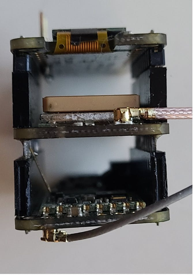
Sandwich the Notecarrier
I use a Feather Wing Doubler to expand the capability of the Notecarrier AF by having two feathers lined up an MCU Feather M0 RFM69 and a Feather Wing OLED for status display.
1 / 2 • Line up of Feathers

Line up of Feathers

Feather Doubler
I set a long stacking header on one of the connections in the Feather Wing Doubler connecting to the Notecarrier AF. The setting worked correctly and both boards were able to communicate between each other and with the note card.
This setting can be useful on other conditions where you want to use more than one Feather Wing.
Side snapshot of the Notecarier sandwich

Side snapshot of the Notecarier sandwich
Sending Data to Notehub
The Notecard API communicates with the hardware by building requests and attaching the JSON structure that contains a command or the payload to send to Notehub.
The notecard is initialized with the following code.
//Initialize Blues WiFi notecard.
void initNoteCard()
{
    //Use I2C interface to communicate with the notecard.
    Wire.begin();
    notecard.begin(0x17,30,Wire);
    //Initial settings for notecard.
    J *req = notecard.newRequest("hub.set");
    //Product identification string.
    JAddStringToObject(req, "product", myProductID);
    JAddStringToObject(req, "mode", "continuous");
    notecard.sendRequest(req);
}
Note that we are using the I2C interface to communicate with the Notecard using address 0x17.
During initialization the Notecard needs to know which project to link with. Above, we create a "hub.set" request, which includes the product identifier and the communication mode (in this case continuous). The sendRequest function commits the request to the Notecard, and executes the command.
We then send the payload to Notehub using the following code:
//Build a NoteCard request object
J *req = notecard.newRequest("note.add");
if (req != NULL) {
    //Add a sync request to the NoteCard.
    JAddBoolToObject(req, "sync", true);
    //Create a JSON object
    J *body = JCreateObject();
    if (body != NULL)
    {
        //Add key and value to the JSON object
        JAddStringToObject(body, "loc", (char *)buf);
        JAddItemToObject(req, "body", body);
    }
    //Send the request to the NoteCard.
    notecard.sendRequest(req);
}
We create a new "note.add" request that will add a note that contains the payload. Then we create the "body" that contains the "loc" key with the data received from the client. We add the body to the JSON object with JAddItemToObject. Finally, we send the request to Notehub using sendRequest.
Below is a snapshot of the events received by Notehub from the Wi-Fi Notecard. Note the payload column denoted by the "loc" label.
Notehub events list

Notehub events list
Saving to SD Card
I wanted to save a backup copy of the geospatial data received from the client, so I decided to connect to an Adafruit Feather M0 Adalogger board via the I2C bus.
//Transmit the data to the Adafruit M0 Adalogger. I2C address 44
//Save every single received point
Wire.beginTransmission(44);
Wire.write((char *)buf);
Wire.endTransmission();
This code starts communication on the I2C bus using address 44, sends the payload, and then flushes the transmission to the Adalogger board.
On the Adalogger board, we set the communication link to address 44, and start a background process to listen if any payload is received. Once it is, it triggers a call to the receiveEvent function.
Wire.begin(44);                // join i2c bus with address #44
Wire.onReceive(receiveEvent); // register event
The receiveEvent function then opens a gpslog.txt file for append, reads through the pending buffer, reads the data, and writes it to the file.
File dataFile = SD.open("gpslog.txt", FILE_WRITE);
while(0 < Wire.available()) // as long as there is data in the wire
{
    // Read data
    char c = Wire.read();
    // if the file is available, write to it:
    if (dataFile) {
        dataFile.print(c);
    }
}
The data is now backed up on an SD card for future analysis.
Client Long Range Communication for Yard MappingThe client device consists of a stack set of an MCU board (Adafruit M0 RFM69), stacked over an Adafruit Feather Wing Ultimate GPS, and an Adafruit Feather Wing OLED board.
The GPS board is connected to an Active GPS antenna and the M0 RFM69 board is connected to a portable radio antenna.
1 / 3 • Long Range Client Stack

Long Range Client Stack

Long Range client stack
Setup
The radio is initialized just like the server-side board.
The GPS is initialized as follows
//Communication speed and GPS settings.
GPS.begin(9600);
GPS.sendCommand(PMTK_SET_NMEA_OUTPUT_RMCGGA);
GPS.sendCommand(PMTK_SET_NMEA_UPDATE_1HZ); // 1 Hz update rate
GPS.sendCommand(PGCMD_ANTENNA);
The GPS board communicates thru the TX/RX pins to the MCU board. The commands sets the communication speed, GPS data format, update speed, and antenna settings.
The client uses the board embedded buttons to tag geospatial characteristics like the main structure, trees and the driveway.
Initialize the board pins
pinMode(BUTTON_A, INPUT_PULLUP);
pinMode(BUTTON_B, INPUT_PULLUP);
pinMode(BUTTON_C, INPUT_PULLUP);
Assign the geospatial code if a button was pressed:
//Check for button pressed.
if (!digitalRead(BUTTON_A) || !digitalRead(BUTTON_B) || !digitalRead(BUTTON_C))
{
    //Assign geospatial code.
    if (!digitalRead(BUTTON_A)) btnPressed = 1; //Tree
    if (!digitalRead(BUTTON_B)) btnPressed = 2; //Home structure
    if (!digitalRead(BUTTON_C)) btnPressed = 3; //Driveway
}
Read GPS data, and parse the string received.
// read data from the GPS
char c = GPS.read();
if (GPS.newNMEAreceived()) {
    if (!GPS.parse(GPS.lastNMEA()))
        return;
}
If the link is fixed format, the GPS data is formatted as follows:
"speed/tag, latitude degrees, longitude degrees, altitude"
If a button was pressed marking a geospatial tag, the tag value is one of "tree", "home" or "drv" (drive).
//If one of the buttons pressed send a geospatial tag.
switch (btnPressed ){
    case 0:
        //Format GPS string.
        sprintf(radiopacket,"%.2f,%.6f,%.6f,%.2f",GPS.speed,GPS.latitudeDegrees,GPS.longitudeDegrees,GPS.altitude);
    break;
    case 1:
        sprintf(radiopacket,"Tree,%.6f,%.6f,%.2f",GPS.latitudeDegrees,GPS.longitudeDegrees,GPS.altitude);
    break;
    case 2:
        sprintf(radiopacket,"Home,%.6f,%.6f,%.2f",GPS.latitudeDegrees,GPS.longitudeDegrees,GPS.altitude);
    break;
    case 3:
        sprintf(radiopacket,"Drv,%.6f,%.6f,%.2f",GPS.latitudeDegrees,GPS.longitudeDegrees,GPS.altitude);
    break;
}
Once the string is formatted, we send it to the server using the following code:
if (rf69_manager.sendtoWait((uint8_t *)radiopacket, strlen(radiopacket), DEST_ADDRESS)) {The function then waits for an acknowledgment that confirms the payload reached the server.
There is a timer check that samples the data every 2 seconds due to the limits the cloud service imposes (Adafruit.io).
Collecting Data
Using a LiPo battery and a cell phone carrier, I did a walk through my yard as if I were mowing the grass.
A successful connection to the server shows when you see a reply message (as below) with an acknowledgement of OK and an RSSI (signal strength) value.
The client starts a session with the GPS board and finds a connection with the satellite system.
Successful Connection with Server

Successful Connection with Server
Walking around the property I was able to tag the main structures, such as trees and the driveway
1 / 3 • Connection stablished, start of data transmission.

Connection stablished, start of data transmission.

Tag a tree

Tag Home structure
NotehubNotehub is Blues Wireless cloud service that collects payloads from Notecards, and routes them to your preferred cloud service.
Here, I use the Adafruit cloud service to display a dashboard with the geospatial data and special tags.
Adafruit.io is a cloud service that allows an entry-level free of charge with 30 data points per second. You need to create an account to access the service.
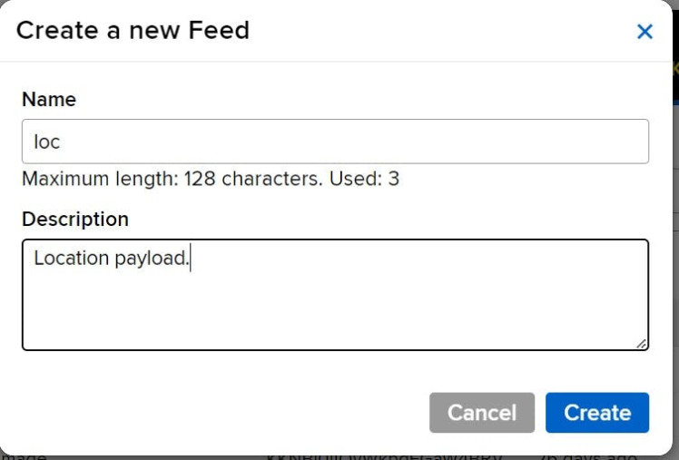
Once you're logged in, create a feed (Adafruit guide). You only need the feed name, loc, and the feed description.
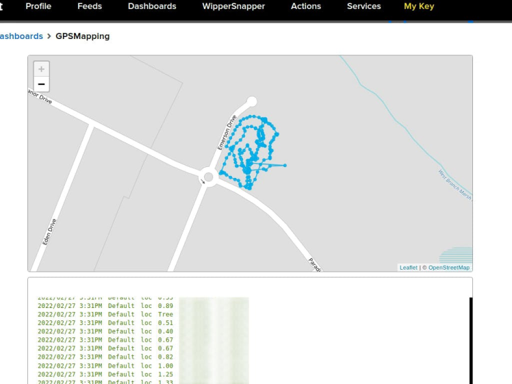
After that, create a dashboard that will display the GPS data as a map and a stream to see the string payload. You can follow the Adafruit guide to create a dashboard here we use a Map and a Stream.
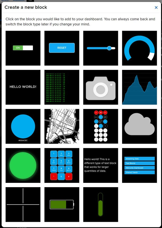
And the final dashboard looks like this.
Route
Back on Notehub, go to your Notehub project, select Route in the navigation, and then click Create Route. Select, "MQTT" from the route options and you should see a form that looks like the image below.
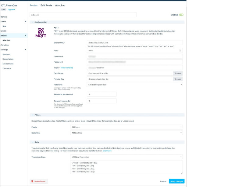
You will need the URL, port, Username, password, and topic. The URL points to the secure address "mqtts://io.adafruit.com" and port 8883. The username and password can be obtained from your Adafruit.io account. Note that the password is not your login password but rather you can get it on the Adafruit.io page under the "My Key" menu on the navigation bar. A dialog will open with the username and an active key use the active key as your password.
The topic needs to point to your created feed, which in this project is loc. So the topic you want to use in your route is "username/feeds/loc", where username is your login username.
JSONata Transformation
In order to plot geolocation data in a map block in Adafruit.io, the service needs the data formatted as a JSON structure as { "value":data, "lat":data, "lon":data, "ele":data}, where lat->latitude, lon->longitude, ele->elevation. The payload we are getting from the Notecard is "speed/tag, latitude degrees, longitude degrees, altitude". Notehub supports the use JSONata a JSON query and transformation language. You can learn how to use it from their "JSONata 1-2-3" guide.
To convert the data from one format to another I used the following JSONata expression.
{ "value": $split(body.loc,",")[0],
 "lat": $split(body.loc,",")[1],
"lon": $split(body.loc,",")[2],
"ele": $split(body.loc,",")[3]}
The $split function breaks the received payload interpreting the data as a comma separated value for "body.loc" (received from the notecard). The first element is assigned to value, which can be "tree" or "home" or "drv". The second element is assigned to lat, the third to lon and finally the fourth to ele. This gives the supported format for Adafruit.io to plot the received data.
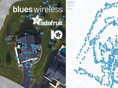
I wanted to know how well the collected data would map to Google maps. Using the "Track Your Treats: Halloween Candy GPS Tracker" project as a guide, I was able to map the saved data on the SD card into personal maps using Google Maps.
Below is the image of all the data points collected.
All recorded points

All recorded points
The following sets of images are maps with home structure, trees and driveway tags shown.
1 / 3 • All tags (Tree and Home)
")
All tags (Tree and Home)

Home tags

Tree tags
ConclusionThe accuracy of the data collected is good enough for the purpose of keeping track of the mown and an initial tagging of tress and the home structure.
Future work will use a more accurate GPS device to mark a geofence around the property that could be used to automatize a robot lawnmower.
AcknowledgementThanks goes to Blues Wireless for being a sponsor of the project thru their program “Most Valuable Hackster”, a great program to motivate makers and the community to create new and exciting projects.
Schematics, diagrams and documents
Code
Credits
Related products


Leave your feedback...