
Making Musicpi: Amazon Echo Music Streamer

Made by NotEnoughTech / 3D Printing / Home Automation / Music
About the project
Stream your local music library to Amazon Echo for FREE!
Project info
Difficulty: Moderate
Platforms: Raspberry Pi
Estimated time: 3 hours
License: Creative Commons Attribution-NoDerivs CC BY-ND version 4.0 or later (CC BY-ND 4+)
Items used in this project
Hardware components


Hand tools and fabrication machines
Story
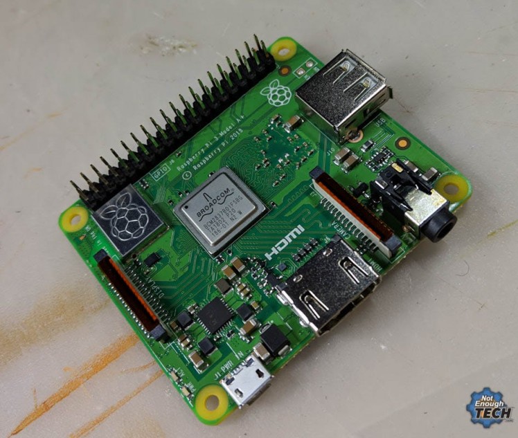
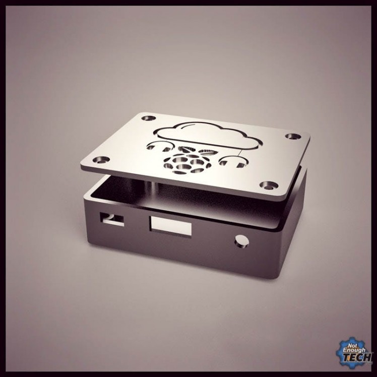
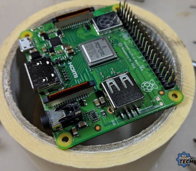
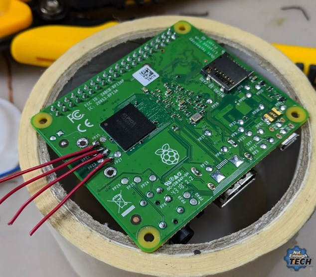
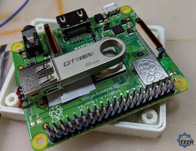
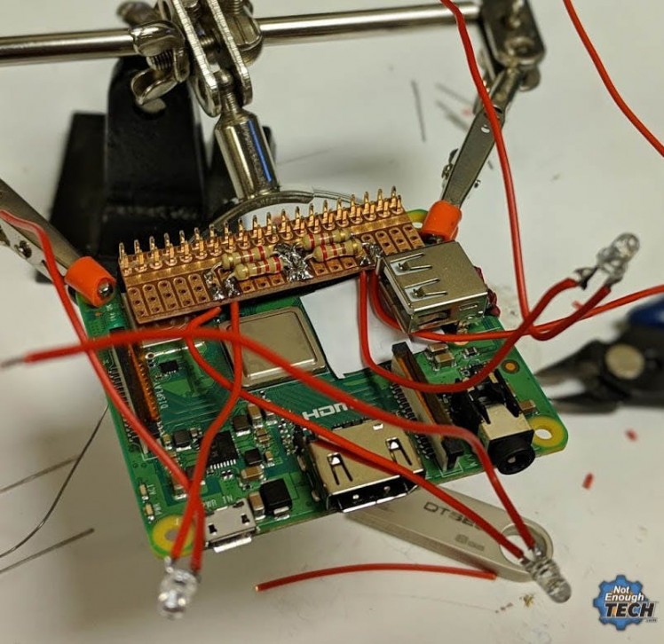
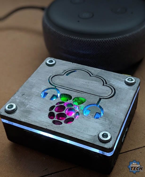
Making Raspberry Pi 3A+ music streaming box has been a great challenge. In a nutshell, the project is very simple: to make something that can store your music locally, and stream it to Amazon Echo Dot smart speaker. Why Alexa? because Amazon Echo Dot 3rd gen sounds incredibly good for its size. I have underestimated how much time it would have taken to complete this project. It’s not “wasted” time, as I learned a lot in the process and I have a lot of fun tinkering around. I thought it would be cheeky and cheap to use a Raspberry Pi Zero to stream the music to Amazon Echo. What started as a simple idea, turned into a complicated solution as the only FREE way of streaming music to Amazon Echo and taking the advantage of voice music controls was via Plex. Unfortunately, Plex has dropped support for Raspberry Pi Zero series, and I needed an alternative board. This is an article about the hardware, so if you are interested in setting the Plex up – read this. With Plex as the platform sorted, it was the time to make some hardware choices. The smallest Pi (apart from Zero) is also the latest one! Raspberry Pi 3A+ is almost the perfect candidate. My requirements were: Raspberry Pi 3A+ Music streamer makes sense! It has the WiFi, it has a single USB port, it’s small and not very expensive. There was one problem, the USB port is ugly, and it would not be compatible with the design I’ve had in mind. At the same time, soldering the USB stick to the board seems excessive! I knew that the part of the case would be 3d printed. I’m new to the 3d printing world but I wanted my Raspberry Pi 3A+ Music streamer box to look pretty. A plastic shell with a solid acrylic lid seemed like the perfect way to go. If you never used the 3d software, don’t be scared. It will take some time to get the hang of it, but it is worth it. I’m so happy I picked the Fusion360 over Sketchup (easier) or Blender because of the issue number 1. The Internet is a great source for everything, providing you remember the rule number one. Everyone can be wrong. I’m no different. I shared some information that was not correct, and I had to redact the info later as someone kindly pointed me to the right information. When conceptualising the first case, I didn’t have the Raspberry Pi 3A+ near, so I used dimensions from the Internet. It was a mistake, the render you see can’t fit my board. The dimensions provided by the image from the Internet was incorrect and I wasted my time and materials. Take my advice and verify the information whenever you can. Make your own mistakes, don’t repeat mistakes made by others. Armed with callipers and notebook, I took all the measurements needed and joyfully proceded to make the mistake number 2. There are easier pieces of 3d software to use out there. Fusion360 is (expensive, free for education) the industry standard for a reason. Bear in mind dear reader I’m not a time served designer, for the most part, I’m just trying things out. My design process should not only take the Raspberry Pi 3A+ Music streamer size in mind but the board and clearances itself. While I left the clearance, I forgot to take it into consideration when adding IO holes. The 2nd iteration 3D print was misaligned! That’s another 2-3h wasted. Thankfully, in Fusion360 all you have to do is to update the dimensions in your sketch and the entire 3D model will be rebuilt for you in seconds. Thankfully, the lid of the case wasn’t affected. Next time I will include the outline of the board in the sketch, this way I will have the reference point each time a design change comes. It will take extra work and time, but in the long run, I will be saving myself a lot of work. I’m sure more experienced designers know this already, but I’m new. I make all the mistakes I can to learn quick! The lid consists of two, 3 mm thick, perspex layers. The top layer is made of a coloured (and painted to look metal) opaque acrylic. The design has been cut out at Teeside Hackspace using 40W laser cutter. It was a small job and it took about 5 min. The bottom part, same in size as the top one is made of clear perspex. The shape of that layer is the same as the top one with the exception of screw holes which are smaller. Because the design is highlighted, the clear acrylics breaks up the case into the lid and the bottom part, creating a very clean looking lip filled with white light. There are 3 pieces of clear film between the clear perspex and the top of the lid. I used simple white LEDs, as RGB LEDs would mix the colours inside the case. I picked a purple (raspberry), green (leaves), and blue (cloud and headphones) colours to change the colour of the highlight. The bottom part of the enclosure has been 3d printed using PLA filament. The print was far from perfect, so I had re-drill the holes so the screws could go in. It’s worth noting, that I ended up enlarging the holes in the board too, so I could use the screws that I already had at hand. The plastic has been sanded down with some sandpaper, then painted black and covered with acrylic varnish. Thanks to the metallic lid and the screws, the entire enclosure doesn’t look too cheap and plasticky. The print job took about 1.5h. I’m not going to pretend, that I carefully planned all this. I worked with all scraps I could find, with random bolts available to me rather than buying the custom ones. The screw holes had to be re-drilled to accommodate for the screw sizes. I could avoid this by measuring the components I found first, but the milk had been spilt and I had to enlarge the holes (including the holes in the Raspberry Pi 3A+) – the takeout from that is – plan as much as you can to save yourself from a headache later. With the design in place, it was time to get rid of the USB port and think of a way to highlight the decal made on the lid. I wanted my case to be small. The USB stick would… well stick out like a sore thumb [someone forgives me these puns]. To solve this, I found very simple in design USB sticks, and I decided to turn the USB socket 180 degrees. This way the USB is facing inwards, I have one less IO element and the case looks nicer. Desoldering the USB socket took ages, I needed it intact, so I had been very careful while doing so. Initially, I thought I would put the USB stick underneath the Raspberry Pi 3A+ board, but pins were not aligned for that and I ended up creating custom wires instead. When soldering the cables to USB pins, make sure the pins do not touch each other or the USB socket shielding. I had a spare piece of prototyping PCB laying around, so I thought I would make a removable HAT. Each LED is connected to a different GPIO, and while my script only turns on the lights on boot, you have the full control of each LED if you want to change the behaviour. The LEDs are connected through 220Ω resistors to ground, and in my design, the GPIOs used are 03, 04, 19, 26. MusicPi: Python lights.py The script is very simple and to run it on boot, you have to make it executable and add it as a crontab job Even though I had been frustrated at times, I had a great time trying to solve every single puzzle I encountered. I know there could be 100s things to improve on, change and modify, but it’s important to see the project through. It gives you the feeling of accomplishment and a tangible reward of having a complete project in your hands. One of the people I follow said: “Fail quickly” – I cannot stress it enough how important is to fail, how to accept the defeat, gain knowledge, rebuild your confidence and iterate. In addition, if you want to get informed about the updates to this or other projects - consider following me on the platform of your choice: And if you feeling like buying me a coffee or supporting me in a more continuous way: I hope you have enjoyed the project!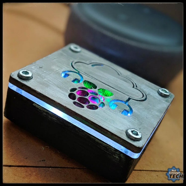
Making Raspberry Pi 3A+ Music Streamer
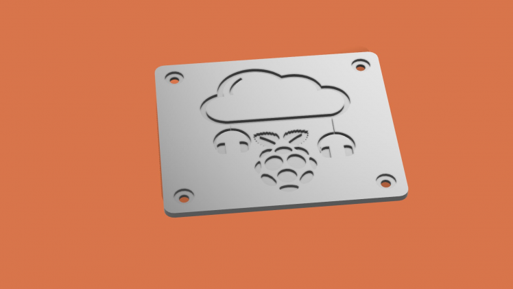
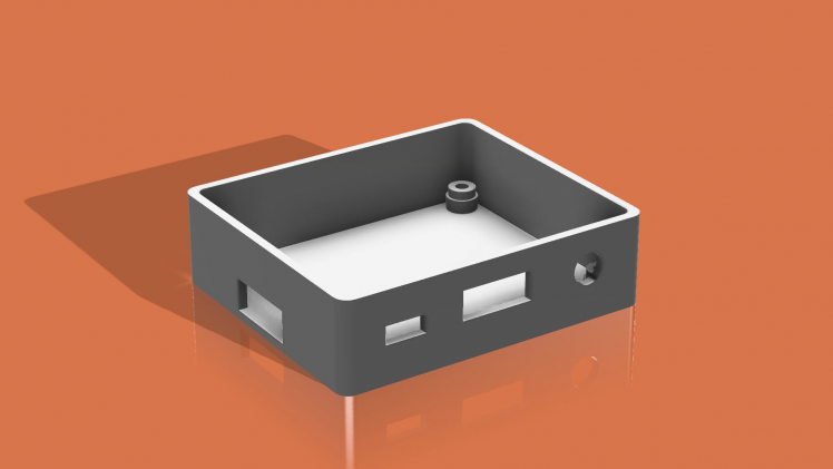
Fusion360 3D Render
Issue #1 – People Make Mistakes
Issue #2 – Fusion360 Is PRO
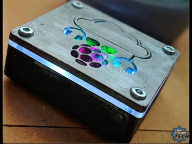
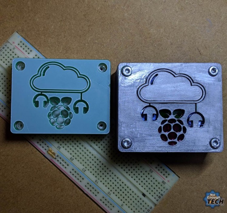
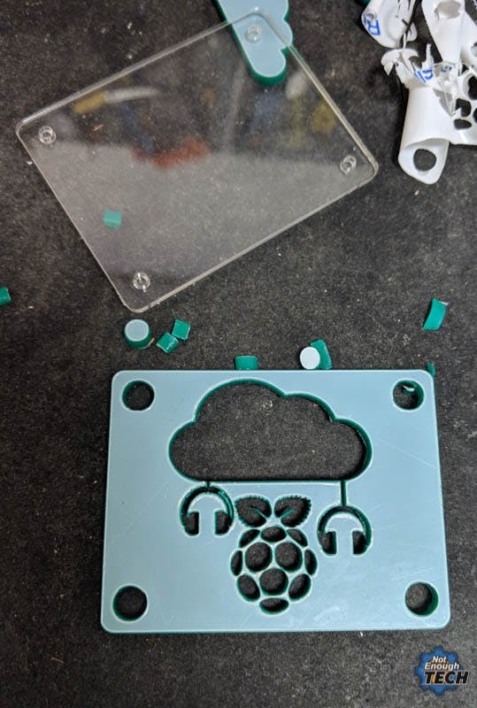
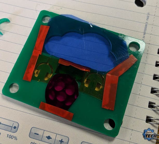
The Lid

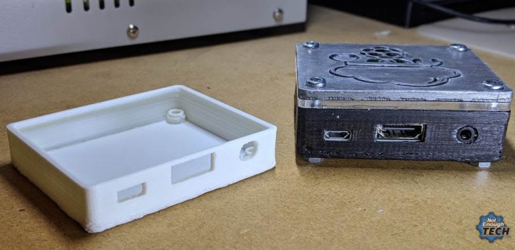
The Case
Issue #3 – It’s Essentially a Scrap Job
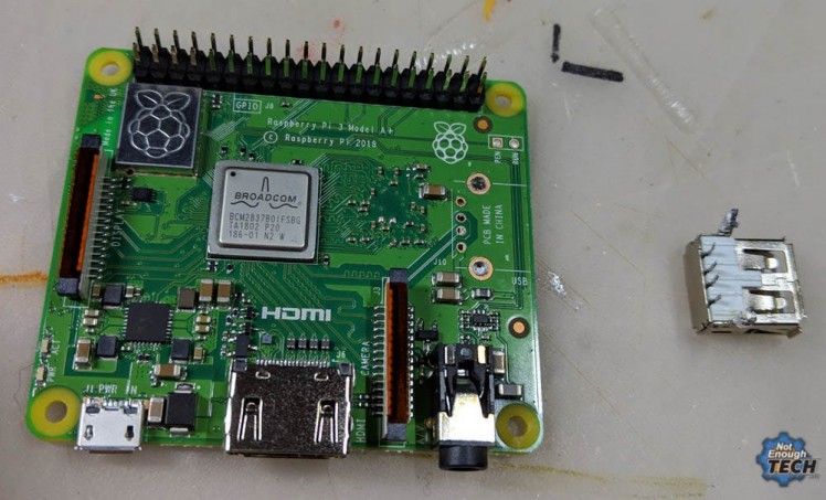
Modding the Raspberry Pi 3A+
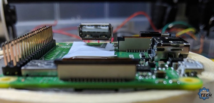
Issue #4 – USB
The 4 LED HAT
#!/usr/bin/env python
import RPi.GPIO as GPIO
import time
LedPin1 = 03
LedPin2 = 04
LedPin3 = 19
LedPin4 = 26
GPIO.setmode(GPIO.BCM)
GPIO.setup(LedPin1, GPIO.OUT)
GPIO.output(LedPin1, GPIO.HIGH)
GPIO.setup(LedPin2, GPIO.OUT)
GPIO.output(LedPin2, GPIO.HIGH)
GPIO.setup(LedPin3, GPIO.OUT)
GPIO.output(LedPin3, GPIO.HIGH)
GPIO.setup(LedPin4, GPIO.OUT)
GPIO.output(LedPin4, GPIO.HIGH)
sudo chmod +x /home/pi/lights.py
sudo crontab -e
@reboot python /home/pi/lights.py &
Conclusion
Schematics, diagrams and documents
CAD, enclosures and custom parts
Code
Credits
NotEnoughTech
Some say I run a decent tech blog online. The truth is I needed to find a hobby that fits between my bicycle rides. Robotics engineer in making at Labman.
Related products


Leave your feedback...