
Making A Lightshow With Arduino

Made by bitsandbots / Art / Lights
About the project
Using an Arduino Nano on an expansion board with a push-button to change the color palette mode of the RGB LED strip. A microphone module I
Project info
Difficulty: Moderate
Platforms: Arduino
Estimated time: 1 hour
License: Apache License 2.0 (Apache-2.0)
Items used in this project
Hardware components


Story
They are in games, decorations, shadow boxes, sign borders, torches, spotlights, and so on...
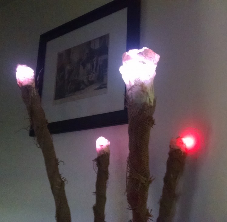 RGB Torches
 Halloween Animatronics
Using an Arduino Nano on an expansion board with a push-button to change the color palette mode of the RGB LED strip. A microphone module is used to detect sound and alter the speed of flashing lights.
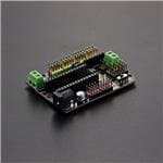
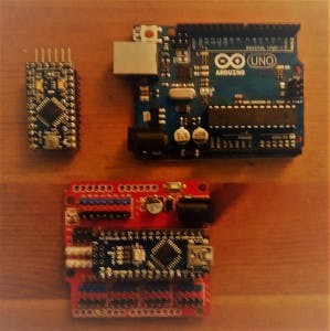 Arduino Pro-Mini, Uno, Nano on Expansion Board
Why Arduino?
The greatest advantage to using the Arduino family of microcontrollers for these types of projects, is that they are ubiquitous. Since they are so available, they are inexpensive and you can find open-source software to get started. If you’ve ever had the opportunity to work with an Arduino Uno microcontroller board, then you’ve probably executed the flashing LED example. Going further, you might attach a button, or switch, to trigger the LED or to turn it off making the project interactive.
There are many sensors that could be connected to the Arduino Uno and setup to trigger events, such as the LED flashing, using threshold values that we would need to experiment with in order to figure out what settings work best for creating the effect we want.
While the examples that come with the Arduino software and the examples included with libraries are an excellent start to a project; the Arduino family of microcontrollers is often grossly underutilized in many projects. Sure microcontrollers are limited in how many instructions it can run and hitting the program size limit doesn’t take very long when you want to control more than a few blinking LEDs.
Even with creative variable handling and custom libraries, eventually, there is a need for another microcontroller or to move to a larger one. In my hydroMazing Smart Garden System and in my Alien Invasion Slot Machine projects, I push the Arduino closer to its limits.
Time Management and state and trigger flags
At its most basic, a microcontroller loops through a set of instructions handling each action with the focus of The Red Eye of Sauron from Lord of the Rings. There are a few interrupts that can be configured should an event be so important to receive the full attention of the microcontroller. Using some form of time management creates a state machine. If x amount of time has passed since x event, then do something and so on...
“The behavior of state machines can be observed in many devices in modern society that perform a predetermined sequence of actions depending on a sequence of events with which they are presented. Simple examples are vending machines, which dispense products when the proper combination of coins is deposited, elevators, whose sequence of stops is determined by the floors requested by riders, traffic lights, which change sequence when cars are waiting, and combination locks, which require the input of combination numbers in the proper order.” https://en.wikipedia.org/wiki/Finite-state_machine
There are rare instances where: RTOS, AI, neural networks exist on microcontrollers, but that’s best left to software-oriented systems such as a Raspberry Pi.
After trying many different timer and time management libraries I felt they were either too much or not enough of what I was wanting in my timers. A set of timers that are easy to set, keep track of their own state, and each have their own trigger flags.
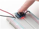
Button assumptions
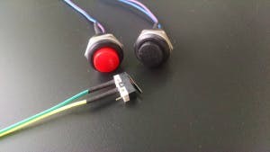 push-button switches
Interacting with an electronics device such as a microcontroller or computer system is relatively easy and typically provided as an example for developers looking to use the device in their project. Press a button and an LED illuminates. A button or switch may seem like a simple sensor input, but it’s not.
The device’s system resources are consumed waiting and watching for a button press. When we use a button in a project we typically think of it being activated when pressed. Then what? What should happen if the user holds the button in the active position? Will the button be counted as pressed once, or is the program going to count each second, or x amount of time, as another button press? Does the program need to know that the button has been released?
Hardware
I’m going to be adding on a lot of peripheral devices and moving away from basic prototyping. Rather than using the Arduino Uno and a protoboard or breadboard for this project, I’m using the Arduino Nano on an expansion board. I’ve created several color palettes by porting the sample code from the FastLED library examples to my base code templates. with a push-button input to change the color palette mode of the RGB LED strip.
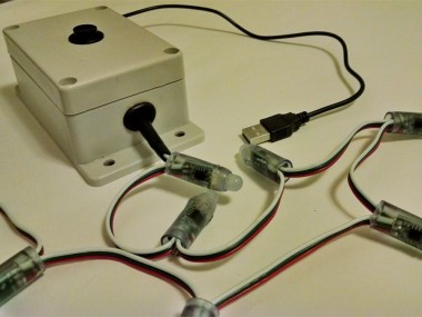
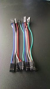 custom wiring harness
Wiring
Keep it simple using common wiring colors, keep it modular so connections can be made with ease, keep your project sustainable; a part can be replaced rather than the entire system. The DuPont wire connectors that come with prototyping starter kits makes it easy to create your own custom wiring connections. The wires are easy to solder when a more permanent connection is needed. I make custom wiring harnesses for neater, cleaner, and more easily connectable modules.
Lighting Effects
There many RGB LED options, so I will be focusing on the WS2811/WS2812 modules. Single RGB LEDs to strings of RGB LEDs in various configurations. Most of the RGB options wil
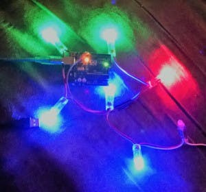 RGB Light String Calibration
l have three wires for connecting to the microcontroller board and require 5vdc or 12vdc. Unless you are designing a new printed circuit board, use DC/DC conversion modules to convert your power to the needs of your project. You might need to step-up voltage from 3v to 5v, or maybe step-down 12v to 5v?
*** The more lights added, the more power needed. ***
The Arduino Uno, and variants, should only be used for directly powering peripheral modules and not devices. Consider the maximum current consumption when determining what is a device and what is a module. A string of lights is more of a device as opposed to a panel indicator light, motor controller boards are modules, not the motors they drive, MOSFET boards, not the valves or solenoids that they control. See Arduino FastLED Library.
Common Options for Power
- USB Powered Devices
- AC/DC wall-wart Power Supplies
- Rechargeable Batteries
- Solar Panels
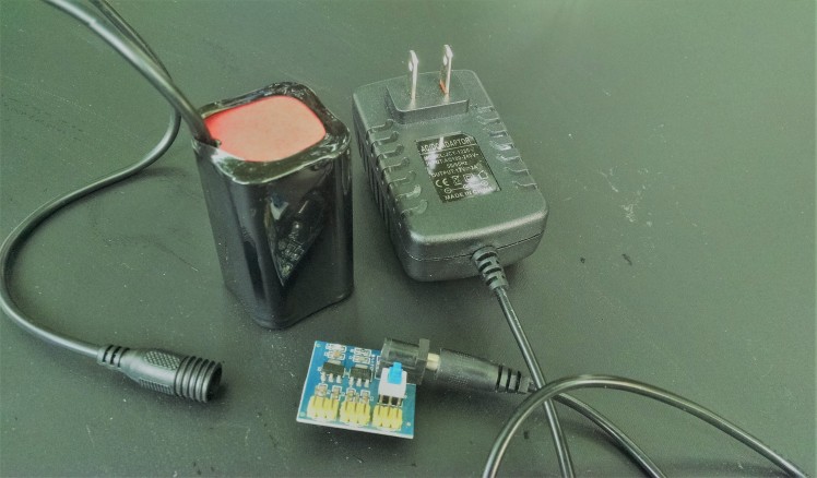 power options
Parts:
- Arduino Nano
- Expansion Board
- USB to mini USB cord
- AC/DC Outlet Power Adapter
- Project Box
- (1-4) strips of 10 RGB 12mm LEDs.
- (1) push-buttons
- microphone
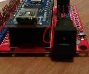 Arduino Nano Expansion Board, watch the pins!!
Steps:
Insert Arduino Nano into the Expansion Board by carefully pressing the Nano pins into the expansion boards headers. Note the picture where only half of the pins are correctly inserted. Plan to provide power using USB to mini USB cord. Optionally, AC/DC Outlet Power Adapter.
Prepare the following wiring connections to the expansion board by soldering and protecting with heat-shrink:
- (1-4) strips of 10 RGB 12mm LEDs.
- (1) push-button
- microphone
Programming considerations:
- brightness of lights
- color palette
- speed of flashing lights
- what triggers change?
Connect the push-button to the expansion board.
Connect strip(s) of 10 RGB 12mm LEDs to the expansion board and upload test code.
Optionally, connect the potentiometer to the expansion board and upload test code.
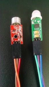 microphone and PIR sensors
Making projects more interactive
Every sensor gives us a data-point to work with, providing an input so that our program can make a decision based on its current environment or what happens when conditions are met. Going further with the project, I’ve added a microphone to detect sound, and at a later time, I’ll add a PIR sensor to detect motion.
Connect the microphone to the expansion board and upload test code.
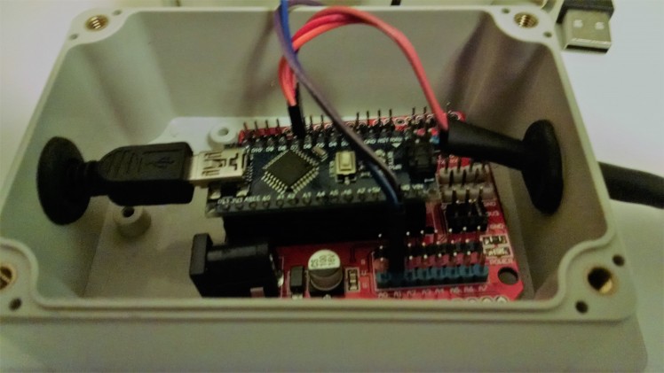 box it up!
Complete the project with an enclosure.
- Drill 7/16” - 1/2” holes into the project box:
- HOLE 1: side ~ USB to mini USB cord ~ Optionally, AC/DC Outlet Power Adapter
- HOLE 2: cover ~ push-button
- HOLE 3: side ~ 1-4 x strips of 10 RGB 12mm LEDs
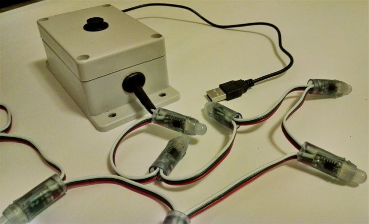 completed project
You can purchase a completed Lightshow directly from me as a functioning example.
Coming soon: Making Sound Effects with Arduino
Please follow me and learn much more at http://www.hydroMazing.com
Schematics, diagrams and documents
Code
Credits
Related products


Leave your feedback...