
Make A Smart Unlock System For Motorcycle - Keyless

About the project
In this blog, I am going to show you how to Make a Smart Unlock System For Motorcycle. This is a great project
Project info
Difficulty: Moderate
Platforms: Arduino, ControlEverything.com, DFRobot, Android Things
Estimated time: 1 hour
License: Apache License 2.0 (Apache-2.0)
Items used in this project
Hardware components

Story
In this blog, I am going to show you how to Make a Smart Unlock System For Motorcycle. This is a great project for people with minimal electronics skills, you can make this within an hour.
This is an inexpensive and easy way to add fingerprint to any bike. this project we have made a fingerprint Scanner for Bike Ignition. We can start our bike with a fingerprint or a key.
Thank You NextPCB:
This project is successfully completed because of the help and support from NextPCB. Guys if you have a PCB project, please visit their website and get exciting discounts and coupons.
Only 0$ for 5-10pcs PCB Prototypes:https://www.nextpcb.com/coupan
Register and get $100 from NextPCB: https://www.nextpcb.com/register.
See more info about PCB Assembly Capabilities: https://www.nextpcb.com/PCB Assembly
Here are mid-summer sales at NextPCB :
1. Up to 30% off for the PCB orders
2. Up to 20% off for the PCBA orders
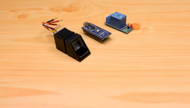
Step 1: Supplies
1 / 3
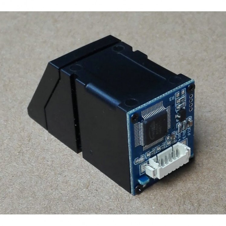
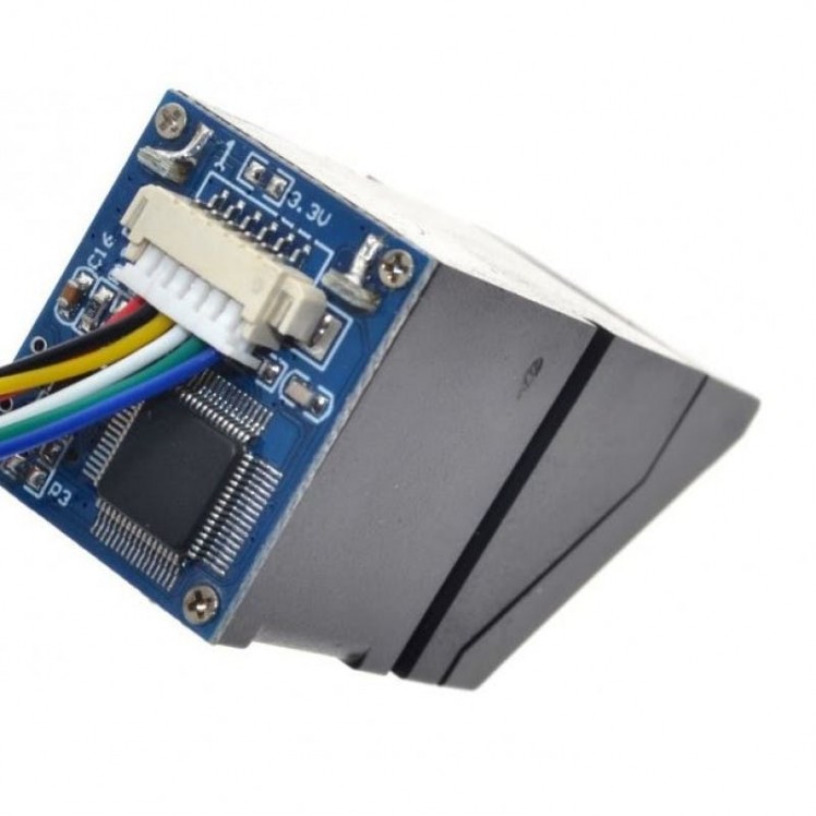
The type of fingerprint module we are using is the R307 Fingerprint Scanner Module.
R307 Fingerprint Module consists of optical fingerprint sensor, high-speed DSP processor, high-performance fingerprint alignment algorithm, high-capacity FLASH chips and other hardware and software composition, stable performance, simple structure, with fingerprint entry, image processing, fingerprint matching, search and template storage and other functions.
Security is a major concern in our day to day life, and digital locks have become an important part of these security systems.
Understanding the Working Principle of Fingerprint Sensor
1 / 2

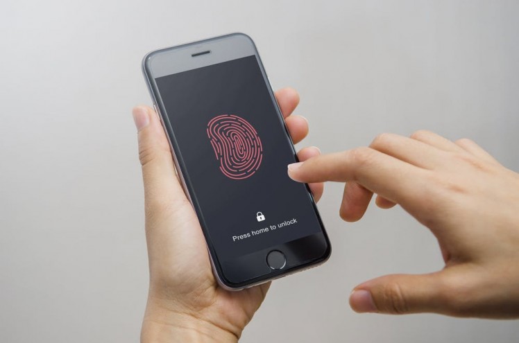
The fingerprint sensor we are using is an Optical Type, there exists two more types of sensor like capacitive which can be found in smart phones and ultrasonic ones, which are yet in testing phase, and both these options are expensive, so we will focus on this optical type for this hobby electronics and similar projects.
The way this optical fingerprint sensor works is that it captures a photo of our finger ridges, and then it uses certain algorithm to match it with stored data and displays result of the same.
few features of this sensor are as following:
- Power supply: DC 3.8V-7.0V
- Operating current: 65mA (Typical)
- Interface: UART (TTL logical level)Average
- Security level: 5(1, 2, 3, 4, 5(highest))
- Working environment :Temp: -20°C to +60°
- Touch area dimension: 14.5*19.4 mm
- Outline dimension: 54*20*20.5 mm
1 / 2
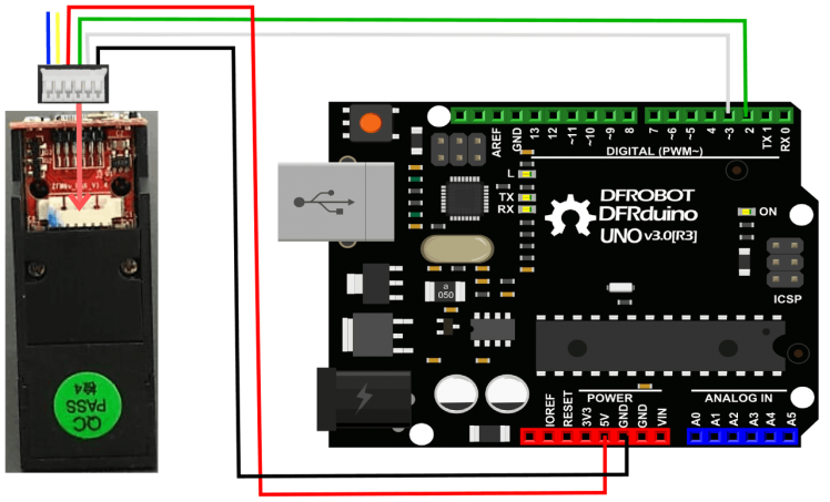
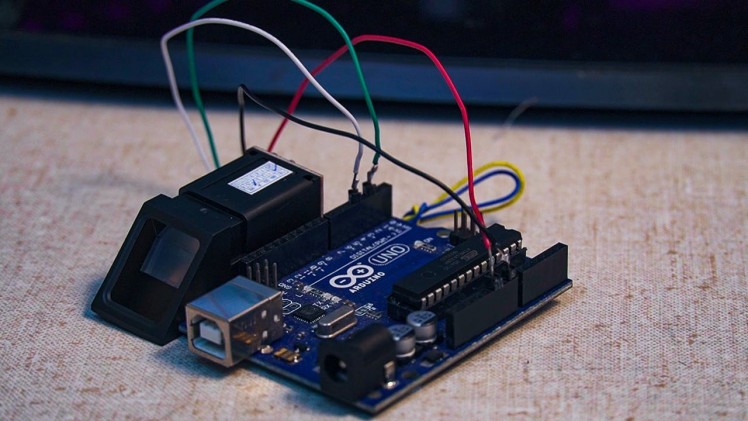
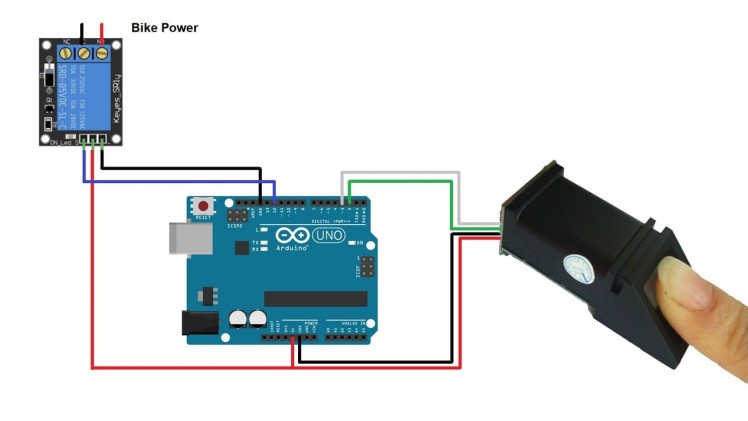
Make the connections as shown in the figure above.
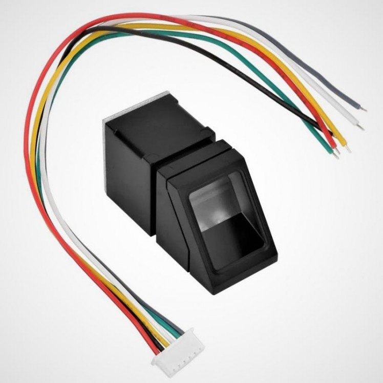
The connections part is very very simple, this fingerprint sensor has 6 wires, out of which we only 4 wires are useful, for arduino interfacing, out of which 2 wires will be used for power and 2 for data.Connections:
- Red to 5v,
- Black to GND,
- Green to pin D2
- White to pin D3
(You can also refer to connection diagram above)
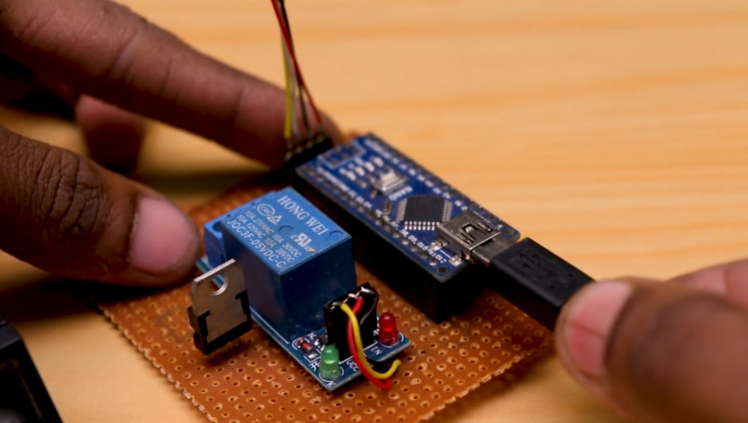
Connect the relay module to input to digital pin 12 of Arduino.
Build Circuit on PCB Board
1 / 5
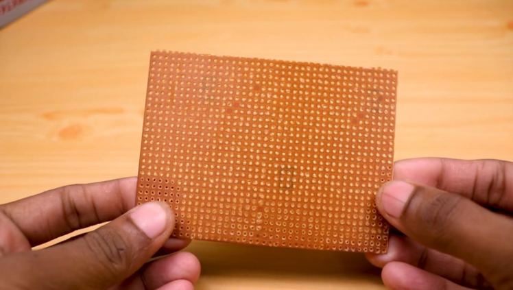
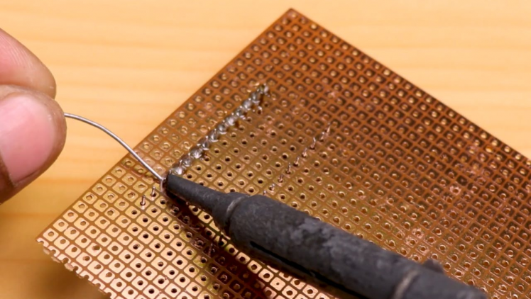
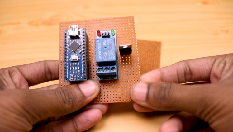
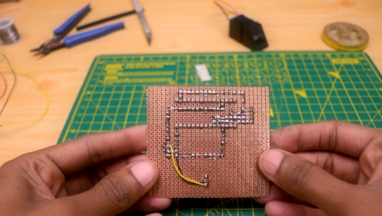
I made circuit on zero PCB Therefore, case you want your own PCB, you can obtain through this link on Nextpcb.com. You can also order good quality PCBS from NextPCB.com at $0 low cost. in addition to the standard pcbs, we could also support advanced pcbs, and other related services that could meet your needs to the most extent.
Include the Adafruits Finerprint Library
1 / 3
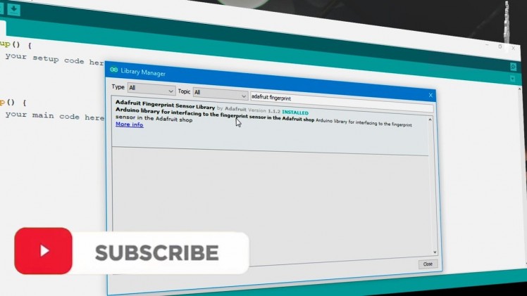
To complete this project or tutorial, we will need "Adafruit's Fingerprint" library, which you can find attached in this step or Google it.
To install that library, follow these steps:
Add the library by selecting Add ZIP under SKETCH menu, INCLUDE Library options.
- Open arduino IDE
- Now, select the.zip file from the location where we downloaded the file!
Enroll the Finger Prints
first we need to enroll the fingers into the EPROM of our Sensor module, so we will follow these steps to enroll our fingerprints.
select the enroll example. Open Arduino IDE
- Under the FILE menu, and Examples, find the Adafruit's fingerprint library.
- Upload the enroll example.
- Open the Serial Monitor.
- Select the baud rate to be 9600.
- Enter the Finger Print ID number when the serial monitor prompts to enter the fingerprint id number.
- Place the finger you need to enroll on the sensor.
- Place the finger again on the sensor once prompted by serial monitor.
Upload the Main Code
Since we enrolled the fingerprints in the last step, now we can test if this sensor works or may be check for match using this following code and steps.
- Open arduino IDE
- Under the FILE menu, and Examples, find the adafruits finger print library.
- Select the fingerprint example.
- Upload the fingerprint example.
- Open the Serial Monitor.
- Select the baud rate to be 9600.
- Place the finger you need to test on the sensor.
- Check for fingerprint id number for OUTPUT.
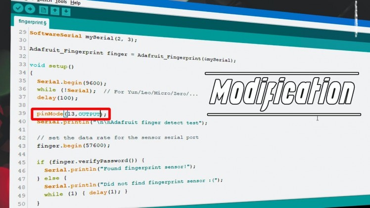
Modify the Main Code to Interface Relay
Now let’s add a led to indicate our Fingerprint match, to do so follow these steps:
use "digitalWrite (13, HIGH); delay(1000); digitalWrite(13, LOW); "on line 144 to turn on and off the Relay
ConclusionIn this tutorial post, we learnt How to Make a Smart Unlock System for Motorcycle and how to use fingerprint sensor with our Arduino, you can use this knowledge to control a door lock, and LED or any apparatus that you want to control.
If you enjoyed this article, don’t forget to pass it along!
Follow me for more DIY projects and ideas and visit my website for more cool projects.
Thank you !!!
Schematics, diagrams and documents
Code
Credits
Related products


Leave your feedback...