


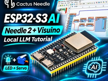
Local Llm On Esp32-s3 - Control A Servo And Rgb Led
Made by Ron / Artificial intelligence / Displays / Home Automation / Lights / Robotics
About the project
Run a real language model locally on ESP32-S3 In this tutorial we run Needle 2 LLM, a compact 45M-parameter tool-calling model, on ESP32-S3.
Items used in this project
Hardware components


Story
Can an ESP32-S3 run a real language model locally? Yes. In this tutorial we run Needle 2, a compact 45M-parameter tool-calling model, directly on an ESP32-S3 with 16 MB flash and 8 MB Octal/OPI PSRAM.
You will type commands such as:
move servo to 90 degrees
blink blue 5 times
move servo to 90 degrees then blink blue 3 times
The sentence goes directly to Needle 2. The Arduino code does not search the sentence for words such as “servo”, “blue”, or “90”. Needle interprets the request and returns structured tool calls. The supplied C++ then validates those structured calls and either sends a normalized value to a Visuino Servo component or controls the onboard RGB LED.
Step 1: What Is Needle 2?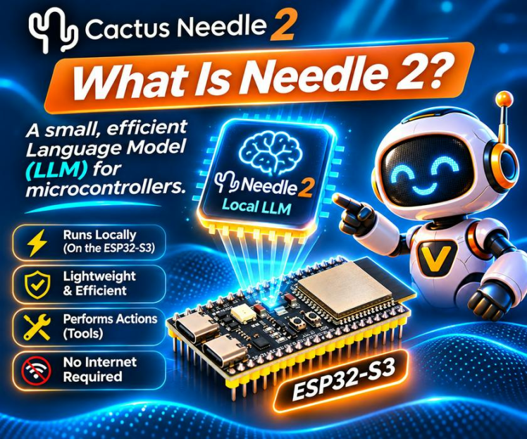
Needle 2 is an open 45M-parameter model from Cactus Compute designed for tool calling, device use, and structured extraction. The official model is distributed as a compact.cact binary. The ESP32-S3 port used by this tutorial memory-maps the model from flash and uses PSRAM for working memory.
This makes Needle especially suitable for embedded control. It is not being used here as a general chatbot. Its job is to convert a human request into a small, structured action that firmware can validate and execute.
The reference ESP32-S3 port targets:
- ESP32-S3, dual core, 240 MHz.
- 16 MB flash.
- 8 MB Octal PSRAM.
- An N16R8-class memory configuration.
- WS2812-compatible onboard RGB LED on GPIO48 on the reference/tested board.
The reference project reports roughly ~47 seconds for a reasoning-on request on its target board; actual time varies with prompt/output length. Long or complex requests can take substantially longer.
Step 2: What You Need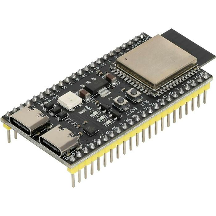

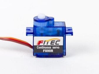
- ESP32-S3 board with 16 MB flash + 8 MB Octal/OPI PSRAM.
- USB data cable.
- Small hobby servo.
- Suitable servo power source, commonly 5 V for small hobby servos.
- Jumper wires and optional breadboard.
- Visuino Professional/ a Visuino edition with the Custom Code component.
- Arduino-ESP32 core. This project was tested with 3.3.10.
- Desktop web browser Google Chrome or Microsoft Edge for the attached local model flasher.
- The supplied Needle2_ESP32S3_Visuino_Files.zippackage.
Visuino demo project (Needle2.visuino) file is also available below
Step 3: Install the Needle2 Arduino LibraryExtract the complete ZIP Needle2_ESP32S3_Visuino_Files.zip.
Copy this folder:
LibrariesNeedle2
into:
C:Users<YOUR_USER>DocumentsArduinolibrariesNeedle2After copying, this should exist:
C:Users<YOUR_USER>DocumentsArduinolibrariesNeedle2srcNeedle2.hand:
C:Users<YOUR_USER>DocumentsArduinolibrariesNeedle2srcNeedle2UserTools.h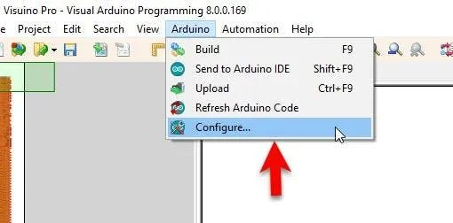
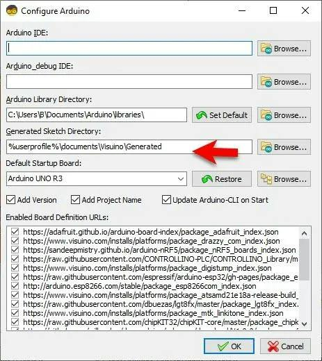
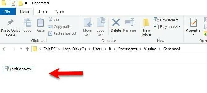
Before we build and upload the project, we need to prepare the custom partition file used by Needle 2.
In Visuino, open:
Arduino → Configure
Under Generated sketch directory, check that the path is:
%userprofile%DocumentsVisuinoGeneratedIf this path is already shown, leave it unchanged.
Now open Windows File Explorer and navigate to:
%userprofile%DocumentsVisuinoGeneratedIf the Generated folder does not exist yet, create it manually.
Next, open the downloaded tutorial files and locate:
Visuinopartitions.csvCopy partitions.csv into the Generated folder.
Before the first build, the folder may contain only:
Generated
partitions.csv
Later, when Visuino generates the Arduino sketch, it will also create:
Generated
Generated.ino
partitions.csv
The filename must be exactly:
partitions.csv
Make sure Windows has not renamed it to partitions.txt or partitions.csv.txt.
This custom partition file reserves the flash area used by the Needle 2 model.
The important model partition begins at:
0x210000
You only need to copy partitions.csv once, as long as you continue using the same Generated sketch directory.
Do not upload the project yet. We will first finish configuring the Visuino components, then compile and upload everything in the following steps.
Step 5: Start Visuino, and Select the ESP32-S3 Board Type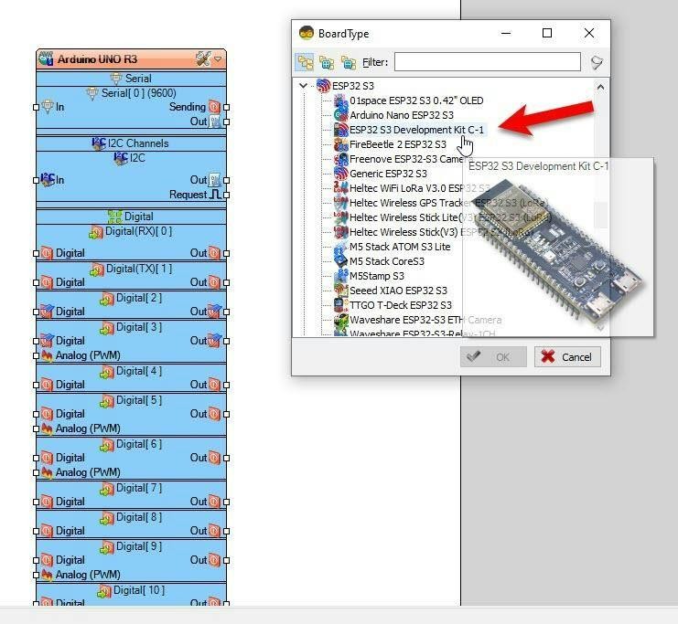
Open Visuino Professional and select:
Board: ESP32 S3 Development Kit C-1
Step 6: In Visuino Add Custom Code and Servo Component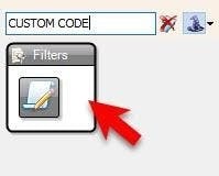
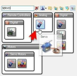
Add these components:
- Custom Code
- Servo
The RGB LED does not need a separate Visuino component in this V26 project; it is controlled by the supplied code.
Step 7: Parse the V26 Arduino Code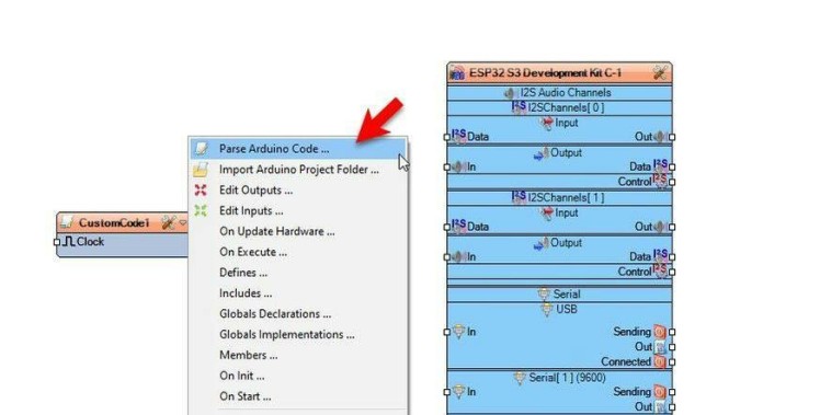
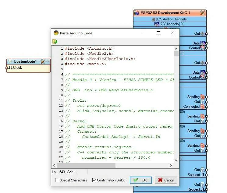
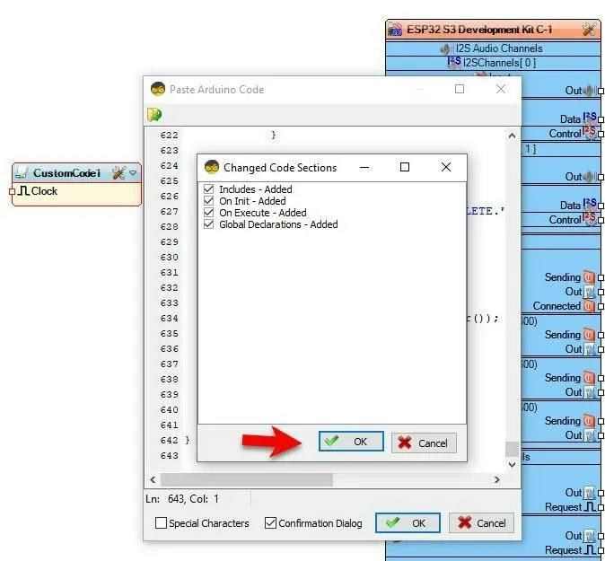
Now we will import the supplied Needle 2 Arduino code into the Custom Code component.
Right-click on the CustomCode1 component.
From the popup menu, select:
Parse Arduino Code
A window will open where you can paste Arduino code.
Open the supplied file in Arduino IDE or notepad:
VisuinoNeedle2_Visuino_LED_SERVO_V26.ino
Copy the complete contents of the file and paste them into the Parse Arduino Code window.
Click OK.
Visuino will analyze the Arduino code and another window will open showing the detected code sections and settings.
Click OK again.
Visuino will now automatically configure the Custom Code component with the required sections, including:
- Includes
- Global Declarations
- Setup code
- Loop code
- Helper functions and other parsed code sections
After this step, the Needle 2 code is imported into CustomCode1 and is ready to be used in the project.
Step 8: Add the Analog1 Output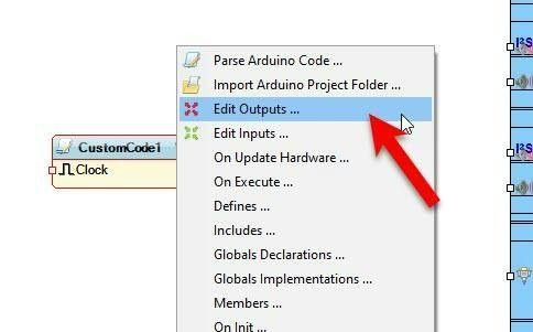
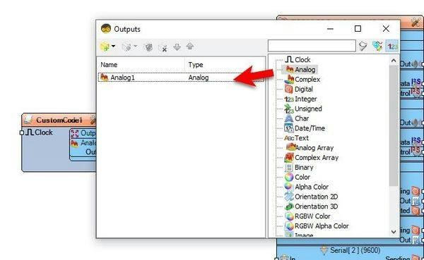
Right-click on the CustomCode1 component.
From the popup menu, select:
Edit Outputs
In the Outputs window drag "Analog" element to the left side
Close the Outputs window
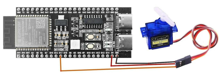
Step 9: Connect the Servo in Visuino and Wire the Hardware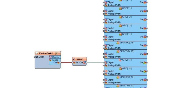
Connect:
CustomCode1.Analog1 → Servo1.In
Connect Servo1.Out to the ESP32-S3 pin you want to use for the servo signal. The tested example can use GPIO17.
Example physical wiring:
Servo signal → ESP32 GPIO17 pin
Servo V+ → ESP32 5V pin
Servo GND → supply GND
Do not power a normal hobby servo from the ESP32 3.3 V output.
Step 10: In Visuino Upload the Project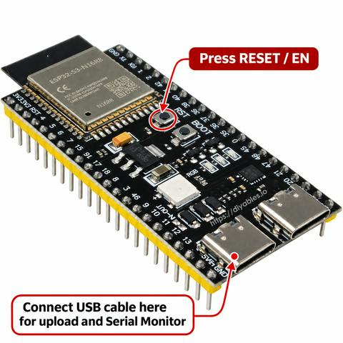
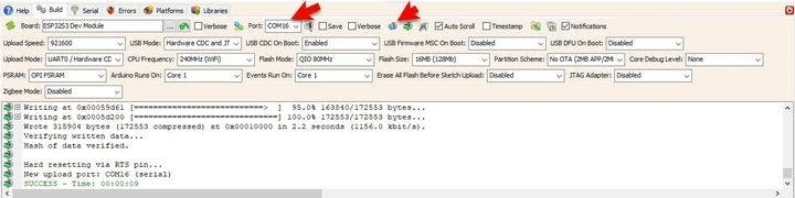
On the bottom tab select Build and set this settings:
Upload Speed: 921600
USB Mode: Hardware CDC and JTAG
USB CDC On Boot: Enabled
Upload Mode: UART0 / Hardware CDC
CPU Frequency: 240MHz (WiFi)
Flash Mode: QIO 80MHz
Flash Size: 16MB (128Mb)
Partition Scheme: No OTA (2MB APP/2MB SPIFFS)
PSRAM: OPI PSRAM
Arduino Runs On: Core 1
Events Run On: Core 1
Erase All Flash Before Sketch Upload: Disabled
Make sure the correct port is selected, then click on the "Compile/Build and Upload" button.
Step 11: Flash the Needle 2 Model With the Local HTML Flasher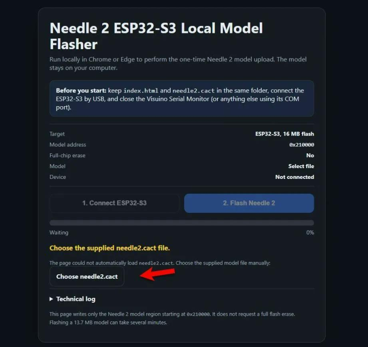
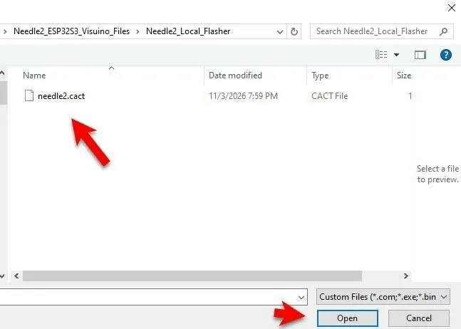
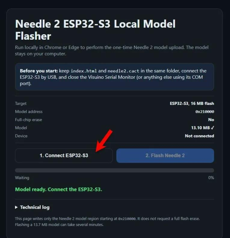
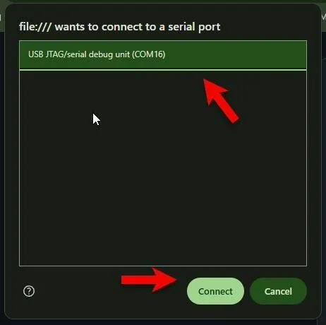
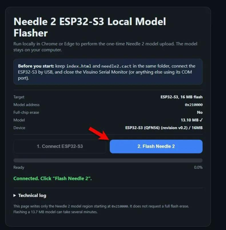
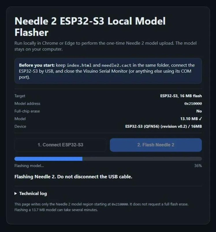
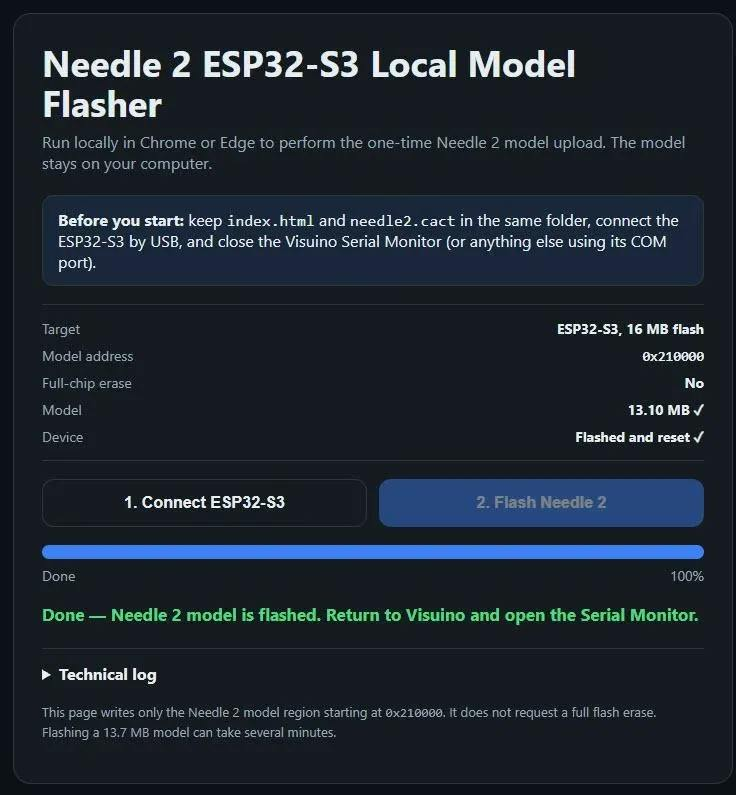
The model is flashed separately from the Visuino firmware. The package includes a local browser flasher, so users do not need Python, esptool commands, BAT files, or a custom board menu.
First close the Visuino Serial Monitor so COM port access is free.
Open this folder:
Needle2_Local_Flasher
Keep these files together:
index.html
needle2.cact
Then:
- Open index.html in desktop Chrome or Edge.
- Click 1. Connect ESP32-S3.
- Choose the ESP32-S3 serial port.
- Click 2. Flash Needle 2.
- Wait until the progress reaches 100% and the page says the flash completed successfully.
The flash address is hard-coded in the page:
0x210000
The user does not type the address.
The page also checks the tested model file before flashing:
Size: 13, 737, 807 bytes
SHA256: b43aabfcaf1a6db6acf488076eab71d823c08697c7af4521fc1d174b60ede5ba
It requests no full-chip erase. On the hardware used while preparing this tutorial, flashing the 13.7 MB model took about 7 minutes; other computers/USB connections may be faster or slower.
The current tested HTML loads Espressif esptool-js 0.6.1 from a CDN, so the PC needs an Internet connection while opening the flasher. The needle2.cact file itself stays local and is sent from the browser directly to the connected ESP32-S3.
If Chrome blocks automatic loading of the local needle2.cact, the page displays a Choose needle2.cact button. Select the copy in the same flasher folder and continue.
Step 12: Play
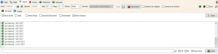
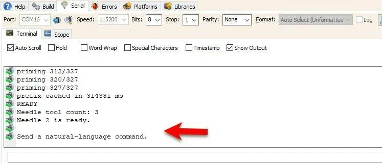
Now we can start the project and check if Needle 2 is running correctly.
Return to Visuino and click the Play button.
At the bottom of the Visuino window, open the Serial tab.
Make sure the correct ESP32-S3 COM port is selected.
For this project, use the same port that was used during upload.
Set the Serial Monitor baud rate to:
115200
Then connect/open the serial port.
Once the Serial Monitor is connected, press the RESET / EN button on the ESP32-S3 board once.
This restarts the board so you can see the complete startup messages in the Serial Monitor.
Wait a few seconds while the ESP32-S3 starts and initializes Needle 2.
If everything is configured correctly, you should see output similar to:
=== Needle 2 + Visuino FINAL SIMPLE LED + SERVO V26 ===
Tools: set_servo + blink_led
Servo output: Analog1
Reasoning: ON
Plan execution: ATOMIC PREFLIGHT
Starting Needle 2...
model mapped: 13762560 bytes
Needle 2 is ready.
The most important message is:
Needle 2 is ready.
This confirms that the Needle 2 model was found and opened correctly and that the ESP32-S3 is ready to receive natural-language commands.
Do not send a command until you see:
Needle 2 is ready.
In the next step, we will send our first command and control the servo.
Step 13: Test RGB LED Control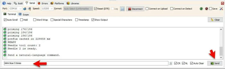
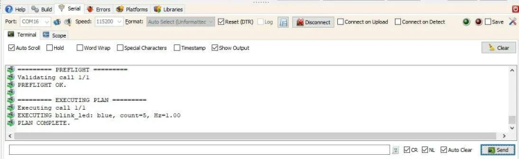
In the Serial Monitor, type the following command and press Enter, or click the Send button:
blink blue 5 times
After Needle 2 processes the request, the RGB LED on the ESP32-S3 should blink blue 5 times.
Next, try setting how long the LED should blink and how fast:
blink red for 20s 2hz
The LED should blink red for 20 seconds at 2 Hz.
You can use these LED colors:
red, green, blue, yellow, purple, white
You can tell Needle 2 how many times to blink the LED, for example:
blink red 5 timesor how long to blink it:
blink red for 20 secondsYou can also specify the blinking speed:
blink red for 20 seconds at 2hzBefore any hardware action is performed, the program checks that the generated values are valid and within the allowed limits.
Tip: For the most reliable results, use short, clear commands written in lowercase, like the examples above.
Step 14: Test Natural-Language Servo Control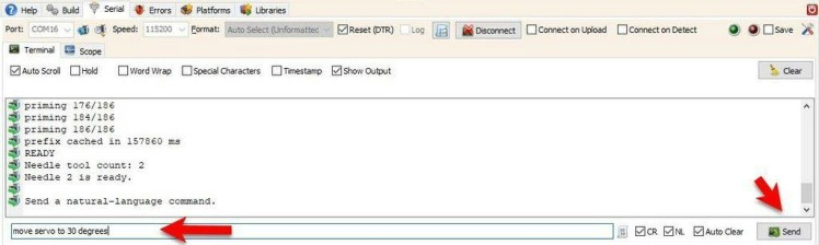
In the Serial Monitor, type:
move servo to 30 degreesand press Enter, or click the Send button.
Needle 2 should generate a set_servo command with the value:degrees: 30
Visuino then converts the angle into the normalized value used by the Servo component:
30 / 180 = 0.1667
The servo should move to approximately 30 degrees.
You can also try:
move servo to 0 degreesmove servo to 90 degreesmove servo to 180 degreesBefore moving the servo, the program checks that the requested angle is a valid whole number between 0 and 180 degrees.
Tip: For the most reliable results, use short, clear commands written in lowercase.
Step 15: Test a Short Multi-Action CommandNow try controlling both the servo and the RGB LED with one command:
move servo to 90 degrees then blink blue 3 times
Needle 2 should create two actions in the correct order:
Move the servo to 90 degrees.
Blink the RGB LED blue 3 times.
Before anything is executed, the program checks the complete set of generated actions.
If one of the actions contains an invalid or unsafe value, the whole command is blocked and no hardware action is performed.
For the best results, keep combined commands short and simple.
Needle 2 is a small language model running directly on the ESP32-S3, so shorter commands are usually more reliable than long or complicated instructions.
Step 16: Practical LimitsNeedle 2 works surprisingly well on the ESP32-S3, but it is still a very small language model running on a microcontroller.
For the best results:
- Use one action at a time, or a short two-action command.
- Avoid long or complicated instructions.
- Use clear values and units, for example: 20s and 2hz.
- Keep the number of available tools small.
- Give Needle 2 time to process the request. Some commands can take tens of seconds.
- Remember that the model can sometimes misunderstand a request.
The program checks the generated commands before controlling the hardware. If the result is invalid or outside the allowed limits, the action is blocked.
This combination works well for embedded AI:
Needle 2 understands the request, while the program checks and safely executes the hardware action.
Step 17: Later UpdatesThe Needle 2 model normally needs to be flashed only once.
For future Visuino changes:
- Keep partitions.csv in:
%userprofile%DocumentsVisuinoGenerated- Keep Erase All Flash Before Sketch Upload = Disabled.
- Build and upload the Visuino project normally.
You do not need to run the HTML model flasher again unless you erase the flash, replace the model, or Needle 2 can no longer find the model.
Normal firmware uploads do not overwrite the Needle 2 model stored at 0x210000.
Step 18: Troubleshooting and Getting HelpTIf something does not work, first check the Serial Monitor output and the Visuino build settings.
Needle 2 needs 8 MB PSRAMMake sure Visuino is configured with:
PSRAM: OPI PSRAM
Then build and upload the project again.
nd_model_open failed (-2)If you see something similar to:
ERR nd_model_open failed (-2)the ESP32-S3 found the model partition, but the Needle 2 model is missing or was not flashed correctly.
Close the Visuino Serial Monitor and run the supplied HTML model flasher again.
Do not erase the complete flash.
Needle 2 cannot find the model partitionCheck that the generated sketch directory is:
%userprofile%DocumentsVisuinoGeneratedand that this folder contains:
partitions.csvThe file must be there before building the project.
Analog1 was not declaredMake sure the Custom Code component contains an Analog output named exactly:
Analog1
Then parse the supplied V26 Arduino code again.
Servo does not moveCheck:
- CustomCode1.Analog1 is connected to Servo1.In.
- The correct servo output pin is selected.
- The servo has a suitable power supply.
- The servo and ESP32-S3 share a common ground.
Then test:
move servo to 90 degreesThis tutorial uses the onboard addressable RGB LED on GPIO48 of the tested ESP32-S3 board.
Some ESP32-S3 boards use a different LED pin or different LED hardware.
Browser flasher cannot connectClose the Visuino Serial Monitor and any other program using the ESP32-S3 COM port.
Then reconnect the USB cable, reload index.html in desktop Chrome or Edge, and try again.
I erased the complete flashUpload the Visuino project again and then run the Needle 2 HTML model flasher again.
Afterward, remember to keep:
Erase All Flash Before Sketch Upload: Disabled
Needle 2 generates the wrong action or blocks the commandUse short, clear commands written in lowercase.
For example:
move servo to 90 degrees
blink blue 5 times
Needle 2 is a small embedded model and can sometimes misunderstand long or complicated requests.
The V26 program checks the generated actions before controlling the hardware, so invalid actions can be blocked instead of executed.
How to Ask ChatGPT for HelpIf you still cannot solve the problem, provide ChatGPT with:
- the complete build/upload log
- the complete Serial Monitor output
- a screenshot of the Visuino settings or wiring if relevant
You can use this prompt:
I am following the ESP32-S3 + Needle 2 + Visuino V26 tutorial.
Hardware:
- ESP32-S3
- 16 MB flash
- 8 MB OPI/Octal PSRAM
Visuino settings:
- Flash Size: 16MB
- Partition Scheme: No OTA
- PSRAM: OPI PSRAM
- Erase All Flash Before Sketch Upload: Disabled
- Generated sketch directory: %userprofile%DocumentsVisuinoGenerated
The supplied partitions.csv is in the Generated folder.
The Needle 2 model was flashed using the supplied HTML flasher.
I am using Needle2_Visuino_LED_SERVO_V26.ino.
Please diagnose the problem from the logs below and give me the smallest thing to check first.
BUILD / UPLOAD LOG:
[paste the complete log]
SERIAL MONITOR OUTPUT:
[paste the complete output]
Step 19: Adding New Needle 2 Tools SafelyOnce the basic project is working, you can add your own Needle 2 tools.
A new tool needs two parts:
- A tool definition in:
Needle2UserTools.h
- Matching validation and hardware-control code in the Arduino program.
The tool definition tells Needle 2:
- the tool name
- what the tool does
- which values it can generate
The Arduino code then checks those values and performs the actual hardware action.
For example, adding a tool definition called:
turn_relay
does not automatically control a relay. You must also add code that recognizes turn_relay, validates its arguments, and safely controls the relay output.
Keep Tools SimpleNeedle 2 is a small embedded model, so keep tool definitions short and clear.
For best results:
- Add one new tool at a time.
- Use simple tool names.
- Keep the number of arguments small.
- Use clear limits for numeric values.
- Validate every generated value before controlling hardware.
- Keep the total number of tools reasonably small.
After adding a new tool, rebuild and upload the Visuino project and test it with short, simple commands first.
Do not rely only on Needle 2 to decide what is safe. The Arduino code should always remain responsible for checking values before any hardware action is performed.
Step 20: FAQDoes Needle 2 need Wi-Fi while controlling the servo or LED?No. After the model and firmware are installed, inference runs locally on the ESP32-S3. No cloud API or PC inference server is used.
Does the local HTML flasher mean the LLM runs in Chrome?No. Chrome is used only as a convenient one-time ESP32 model flasher. Needle inference runs on the ESP32-S3 afterward.
Does the flasher create the partition table?No. partitions.csv creates the custom model partition during the Arduino/Visuino firmware build. The HTML flasher only writes needle2.cact to 0x210000.
Why select No OTA if we use a custom partition table?It gives Visuino a normal built-in board-menu selection. Arduino-ESP32's build system gives precedence to a partitions.csv placed in the sketch folder, so the supplied CSV becomes the actual partition layout for this project.
Do I need the old Needle2 16MB partition menu entry?No. This updated tutorial intentionally avoids it.
Do I need Python or a BAT file?No for the normal tutorial flow. The supplied local HTML flasher handles the model upload in Chrome/Edge.
Do I have to flash the 13.7 MB model after every code upload?No. Flash it once, then keep full-chip erase disabled. Reflash only after a full erase, a model change, or a model-open failure.
Can I add more tools?Yes, but keep the schema compact and add matching deterministic C++ validation/execution for each new tool.
Step 21: Model License and RedistributionThe bundled needle2.cact model is from Cactus Compute's Needle 2 release and is distributed under the Apache License 2.0. Keep the included license and attribution/third-party notice files with redistributed copies of the package/model.
The surrounding tutorial can use a different content license; the model remains under its own Apache-2.0 license.
Step 22: ConclusionYou now have a genuine local tool-calling language model on an ESP32-S3 interpreting natural-language requests and controlling hardware through Visuino.
The important architecture is simple:
Needle 2 = language understanding
C++ = bounded validation and execution
Visuino = visual hardware integration
The updated setup also removes the most awkward parts of the older process: there is no custom partition menu to install and no Python/BAT model-flashing command. Users select the standard No OTA option, keep the supplied partitions.csv in the configured Generated sketch directory, and flash the model from a local Chrome/Edge page.
Step 23: Technical References- Needle 2 model: https://huggingface.co/Cactus-Compute/needle2
- Needle 2 ESP32-S3 port: https://github.com/andrisgauracs/needle-2-esp32
- Arduino-ESP32 custom partition tables: https://docs.espressif.com/projects/arduino-esp32/en/latest/tutorials/partition_table.html
- Espressif esptool-js: https://github.com/espressif/esptool-js
- Visuino: https://www.visuino.com/
Schematics, diagrams and documents
Code
Credits
Related products





Leave your feedback...