

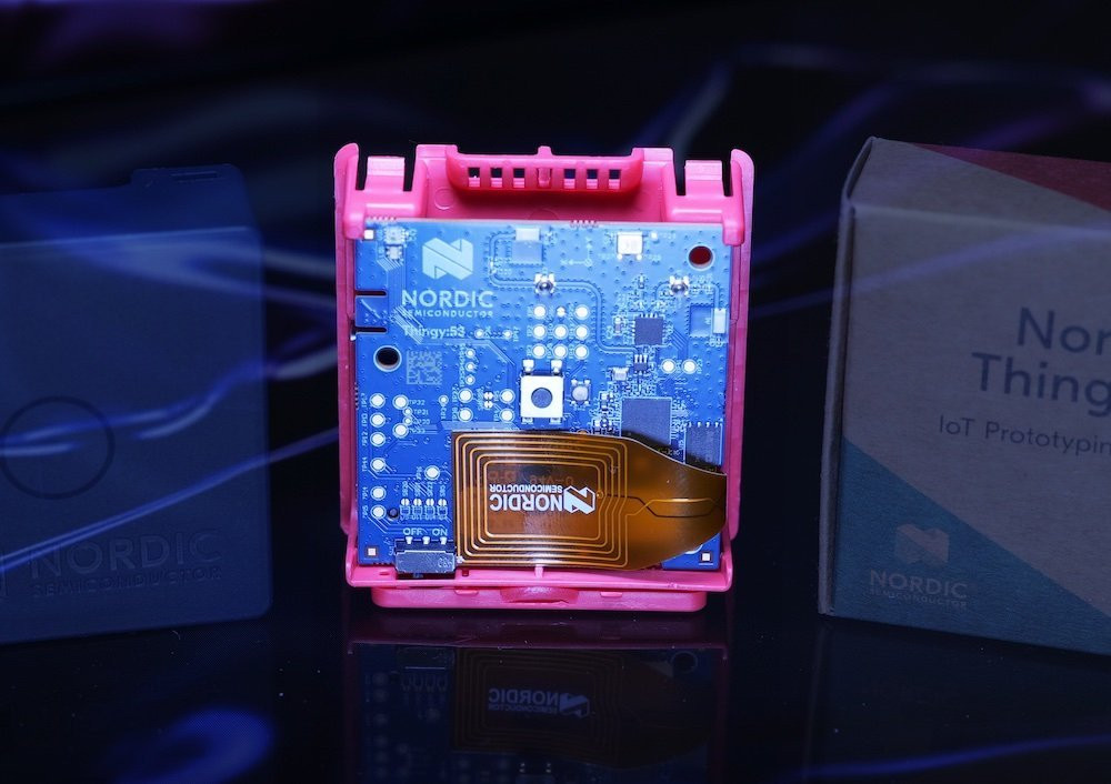
Kitchen Activity Detection By Thermal Sensor Array Thingy:91

Made by jens-ajisai / Home Automation / IoT
About the project
Detecting kitchen activity like boiling water on the gas cooking stove, running dish washing machine or just human presence using a mlx90640 sensor connecting it to the Thingy:91. This project is very much focused on software development aspect such maintainable reusable components, wireless debug support and updatability.
Project info
Difficulty: Expert
Platforms: Nordic Semiconductor
Estimated time: 4 months
License: GNU General Public License, version 3 or later (GPL3+)
Items used in this project
Hardware components


View all
Software apps and online services
View all
Hand tools and fabrication machines
Story
Target
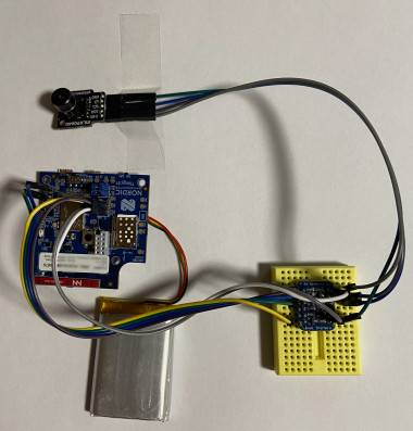
This project aims to build a kitchen activity monitor using a mlx90640 thermal grid sensor array and a Thingy:91 with its environment sensors onboard that can detect basic events like
- Presence detection
- Cooking is ongoing, boiling water finished
- Dish washer finished
- Oven finished and cooled down
Combining these events/states I would like to detect
- Forgot that water is continously boiling or soup is boiling after warming up
Motivation
- I was very curious to use a thermal grid sensor as it opens up use cases that other sensors cannot (easily) do like sensing heat producing devices over the room, check the isolation of your house, detecting where people (or animals) are, etc. So this project justifies to buy one to try it out.
- We are used to build water every day (for tea), sometimes we forgot the boiling water. (you should not leave fire unattended!) Our multifunctional oven toaster microwave oven needs to cool down after toasting to be able to warm up food with the microwave oven. So the idea was to detect when water is ready or oven is cooled down.
- I wanted to gain software development skills with learning by doing. So this project shall deepen the knowledge into real time OSs (Zephyr) and software architecture - aiming to have re-usable assets to speed up future projects. Actually I used parts of a previous project and have a side-project re-using modules.
Current State
- The analysis part is currently just forwarding the data. AI is more work than initial estimated. So it will be a follow up.
- However most of the parts are done like reading sensors and forward to BLE companion app and the cloud. As this project focuses on software engineering, probably not so exiting I guess.
Why Thingy:91?
- It has a connection to the cloud that is independent of the local wifi or even power. So notifications arrive in these cases.
- There are already several sensors integrated and extensive sample applications (which I perceive as well engineered) are available.
- It comes with an SDK that is based on a RTOS Zephyr, has services like Memfault or Edge Impulse integrated which I want to learn and try out. Questions in the Nordic development center are actively answered. A hardware debugger is available with the DKs. So support structure is very fine (also accessible for hobbyists).
- Though this time it will be wall powered, I would like to re-use parts of the application for future low power projects.
However a full blown RTOS (Zephyr) and a multi-core multi-MCU architecture comes with several challenge.
Challenges
Complex Hardware Architecture.
- The Thingy:91 is made of two MCUs: nRF9160 and nRF52840.
- LTE-M functionality is available on the nRF9160 and BLE functionality on the nRF52840.
- Sensors are connected to the nRF9160, but spare pins for additional sensors are only available on the nRF52840 (excluding test points)
- Communication to nRF9160 via UART is only available through running dedicated code on the nRF52840.
- Debugger connection selected by a switch, one at a time.
No mlx90640 driver available in Zephyr
- The sensor driver needs to implemented. Sensor API samples only sent non-array data.
Mlx90640 produces large data
- Each sensor reading is a 32 * 24 float array, which is 3,072 bytes. Reading ever 10s would be about 25MB per day. This is quite large for sending readings via BLE (takes long) or mobile connections to a cloud storage (expensive) - if the cloud storage supports this size on its free tier.
Machine Learning?
- Although you can find references for images, time series (audio) or single point temperature readings. There is hardly any info on low resolution temperature arrays. There is no tutorial for handling videos.
Key takeaways / learnings
- Try to keep you application as simple as possible. → Think well in advance and only implement what you need. (e.g. concurrent BLE connections?) This is a very tricky balance if you want to stay re-usable.
- For re-usability make the modules self-contained without direct dependencies on each other. → I introduce one business logic module that combines all modules. Each module has and interface to receive commands and to respond to them.
- Use a code versioning system, test each change before starting any new implementation and do not forget a commit for each change (even if you work alone) - Time Machine rescues you when you forget it. With Zephyr it is quite easy ending up in a software that crashes soon after startup taking hours to figure out what happened. Changing one configuration item is enough. You can always see the diff what you changed besides rolling back to the last working state.
- These are the most frequent issues causing long debugging sessions (time killers)
- A wrong (combination) of KConfig configurations → Understand each item related to your feature and take into account implicitly set configuration e.g. in the board settings. (VS Code helps a lot here)
- Making features switchable on/off by fragments is hard as you need configuration sets that might conflict with each other. Also conditional compilation clutters up code. Bugs are easily introduced and testing all combinations is a lot of work. → Have all features active. Split up KConfig files and group them with the code of each feature by Cmake.
- A too small buffer KConfig including stack sizes especially for BLE → Start with high values and optimize at the end or when you run out of memory by using the Stack Analyzer feature. See also Memory footprint optimization of the nRF connect SDK documentation.
- Dynamic memory allocation handling (memory leak, double free) over thread boundaries as I had to handle large sensor data and used the Event Manager architecture with many Threads → Create your rules and stick to the like "the one who allocates memory is responsible to release it" or "copy memory on thread boundaries". Think twice if you need a thread for each module. Think twice if you need dynamic memory allocation at all.
- Issues with MacOS. Due to a bug bluetooth was not available for command line utilities. Sever access control for bluetooth.
Overall Architecture
Functionality distribution over MCUs
Given the Thingy:91 hardware as described in the Challenge: Complex Hardware Architecture chapter above I considered the following 3 setups
- Write an app for the nRF9160 and use the nRF52840 as a BLE network core via HCI. (See Bluetooth: HCI low power UART)
- Write an app for the nRF52840 and control the nRF9160 with the AT commands (See nRF9160: Serial LTE modem). AT commands for sensor readings, https or mqtt are available.
- Write apps for both and let them communicate for example sending Json messages via UART.
As there are no spare pins for the nRF9160 broken out (there are test points though), I cannot add my sensor, so I ruled out #1 (I was not confident soldering to test points on this expensive device). Also the HCI UART app does not pass thru UART to the nRF9160 by default.
#2 Requires reimplementing the sensor drivers as only raw twi (i2c) is available. I ruled this out as it sounded a lot of work and I was not aware of the full possibilities of the Serial LTE modem firmware.
So I chose #3 and accepted the added complexity.
Looking back at the end of the project, I would now choose a different solution. Managing two MCUs is eating up a lot of time. I would now choose #2 and not use the built in sensors. Well, without Nordic providing Thingy:91s for the contest, the nRF9160 Feather would have been a consideration. There are enough pins to attach an SD card and a Camera for data collection needed for the machine learning part.
Organization of the source code
The following folders are in the repository
- data contains collected sensor readings and a jupyter notebook for some analysis
- dataCollector contains source code of the site project for collecting data to SD card
- documentation contains drawings and documentations
- heaty_companion contains the flutter companion app source code
- modules contains re-usable components used by all 3 applications targeting nRF MCUs
- nrf52840 contains the source code for the nRF52840 core
- nrf9160_ns contains the source code for the nRF9160 core
- scripts contains python scripts to connect to ble services, build scripts, memfault helper scripts and diagram generation scripts
- test contains test data and mock sensor reading data
- the root folder contains the key for mcuboot
Static View by a Component Diagram
The following diagram describes the software components of the project.

The following is a description of each components purpose.
- Development PC
- Mcumgr Tooling to update the firmware over USB or BLE
- Serial Console Tooling to receive logs and connect to the shell for testing purpose
- Python Scripts to connect to BLE Services to transfer sensor readings or bridge mcumgr to nRF9160 for wireless firmware updates
- Socat is a command line tool to creates virtual bi-directional streams to make BLE UART appear as an UART device.
- nRF52840
- USB CDC makes UART connections accessible via USB for updating firmware, logging and shell commands
- BLE transfer sensor readings, control sensors, updating firmware, logging and shell commands wirelessly
- Shell enables commands for testing purpose like mocked sensor readings and try out newly implemented functionality isolated.
- Mcumgr handles the firmware update on the device
- Diag provides functionality to forward Memfault data
- Watchdog checks if sensor data is delivered periodically and resets the device if not
- Mlx90640 communicated with the mlx90640 to initialize, configure and periodically read it
- Sensors takes care to initialize, configure and read sensors.
- Comm Ctrl implements the business logic and connects other modules by processing and forwarding data. A copy of the Nordic Connectivity Bridge application is included to establish UART connection between PC and nRF9160
- MCU exchange communicates between the nRF MCUs via JSON strings on UART.
- nRF9160
- Mcumgr, Shell, Watchdog, Diag, MCU exchange and Sensors take over same functionality as on the nRF52840
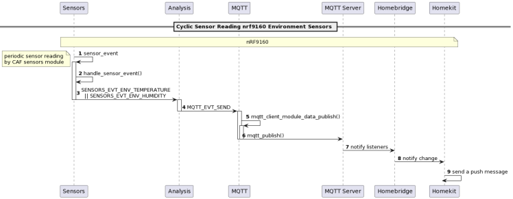
- Sensors (CAF) reads the built-in sensors via the CAF framework
- LED (CAF) visuzalizes the device state like error controlled by the Diag component
- Analsis receives all sensor readings, extracts meaning and forwards the results to the MQTT component. Includes machine learning integration.
- MQTT connects to a MQTT server to send the analysis results
- Modem is the Nordic Modem library to transfer data via LTE-M to cloud services
- Cloud
- Memfault is a service for aggregating app statistics and supports debugging falfunctions.
- Edge Impulse is a service to integrate deep learning “AI”
- MQTT server is a message bus to receive and distribute messages
- HomeBridge converts smart devices into homekit accessories
- Mobile
- Companion App is a BLE application to visualize sensor readings and to configure sensors
- HomeKit is an App by Apple to control smart devices.
Modular Architecture connected by Events
The Application is based on the Application Event Manager Library as it is used in the Nordic Applications like the Asset Tracker V2. The modules are structures like modules in the Nordic Applications using their own thread and messages to pass incoming events to this thread. Depending on the module's state and the event type an action is invoked.
Dynamic View by Sequence Diagrams
The following diagrams describe major flows of the application
- Startup Sequence
- Periodic Sensor Readings
- Firmware Update
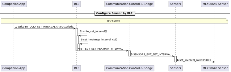
- Sensor Control
To simplify I left out parameters and lower level functionality. This is exactly following UML specifications (like separate arrows for blocking/non-blocking functions).Some functionality is summarized by notes. Function calls end by brackets, events include EVT in the name and are spelled in capital letters.
Some diagrams are hard to read. Please find them also as attachments.
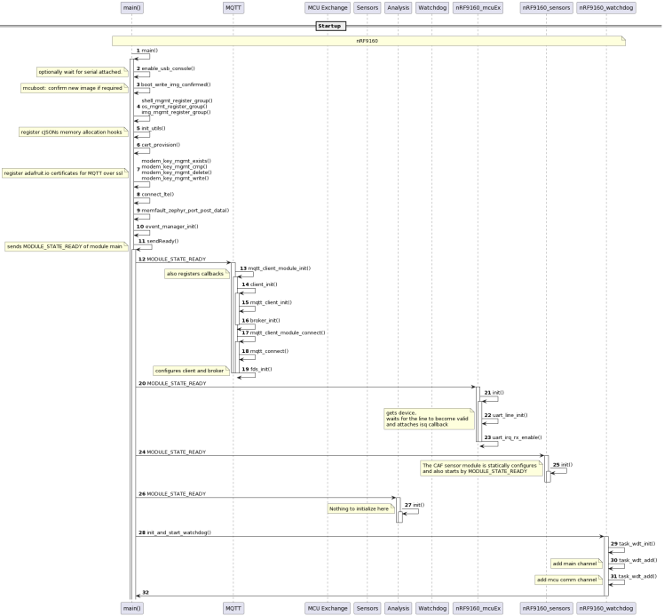
Startup Sequence

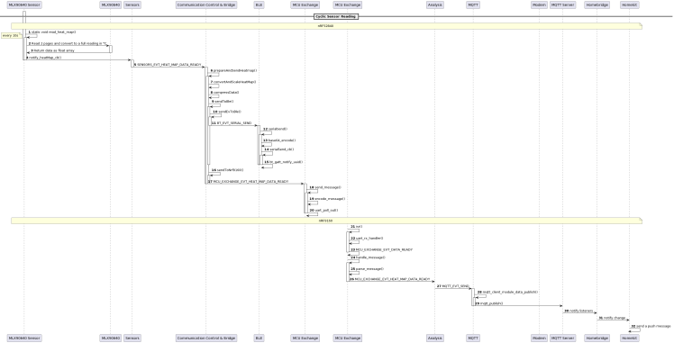
Periodic Sensor Readings
Firmware Update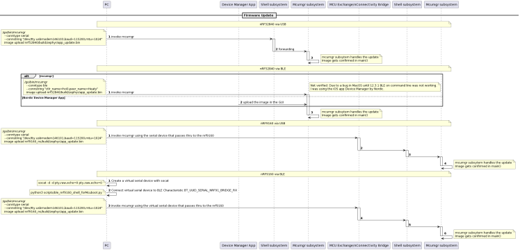
Sensor Control
Feature View with Remarks on Implementation
This chapter goes through the features and mentions implementation details where special consideration was required diverging from sample applications or issues had to be overcome.
Logging (USB Serial Connection)
It is possible to create up to 3 USB Serial channels with the cdc-acm-uart driver. The original plan was to have a logging and shell for each MCU to keep the shell clean when doing mcumgr firmware updates, which would have been 4 connections. It is possible to issue a shell command to halt logging before initiating an update.
To do so specify them in the device tree by creating an overlay file. These USB serial can be assigned to Zephyr functionality like console or shell via the chosen entry. See nrf52840/boards/thingy91_nrf52840.overlay
Logging configuration is defined as an overlay. I added overlays to the CMakeLists.txt instead of specifying them separately in the command line or when creating the Project for the IDE. It simplifies reloading the project and shortens commnads.
I am using the Log2 variant (CONFIG_LOG2_MODE_DEFERRED) so that I do not need to take care about logging strings. The deferred mode is used instead of immediate because immediate mode leads to crashes (maybe due to BLE?). Unfortunately on hard fault valuable logs are missing. So I also tried RTT and a debugger.
When using the deferred mode increasing the log buffer size might be a good idea if there are many messages that otherwise would be dropped.
In case of USB UART, the serial console on your host PC needs to be re-opened on each startup. As this takes time, the logs directly after startup are lost. Therefore I created a KConfig to wait for the serial to be attached by polling the line by uart_line_ctrl_get(). Take care that you have the option CONFIG_UART_LINE_CTRL enabled, otherwise the function waits infinitely without any error. See modules/usb_console.c
Shell
The shell feature is really handy during development as many zephyr modules offer shell commands. I used available commands to control logging, updating via MCU Manager or make Memfault exports.And I also added my own commands to test functionality like mocking sensor readings or printing my memory statistics.
BLE
The BLE connection can handle 2 concurrent connections. One is intented to communicate with the sensors from the companion app and the other for logging and updates for a PC. Handling multiple connections was more complex than though because you need to
- manage multiple connection references,
- advertising should continue as long as not all connections are in use
- MTU size needs to be managed per connection
- services like BT NUS seem to manage only one connection
- and when notifying or sending data you need to select the correct connection.
So think twice if you really need it.
Services are created in a reusable way. The service itself declares all services and attributes. All functionality for reacting to a value written is given as callback to an init function.All functionality for sending notifications or setting values are defined in the interface. These functions take a connection parameter to decide if the notification shall be sent to all or a specific connection. I specified characteristics to control values and send sensor readings in a UART like manner encoding in JSON and base64 as 768 bytes exceeds the MTU size. I also read the maximum supported MTU size (increased buffers to about 250 bytes) and apply it.
The Shell and the bridge to the nRF9160 are also available via dedicated services.
Firmware Updates
The firmware can be updated via the following possibilities
nrf52840
- USB Uart using the MCU Manager SMP Shell
- BLE GATT using the MCU Manager SMP Bluetooth
nrf9160
- USB Uart using the MCU Manager SMP Shell via the UART bridge running on the nrf52840
- BLE Uart using the MCU Manager SMP Shell via the BLE UART bridge running on the nrf52840
Actually the mcumgr tool does not support Serial style updates via BLE, so a workaround to make mcumgr think it is talking to a serial connection is required. I am using the socat tool in combination with a python script that forwards the virtual terminal to the BLE serial service. Increasing the MTU size helps a lot for increasing the transfer rate. See scripts/ble_nrf9160_shell_forMcuboot.py
Memfault integration
I decided to integrate memfault to detect errors early and also when the device is running in production mode.
The Memfault integration for the nrf9160 is done according to the documentation and samples by setting appropriate configurations in overlay-memfault.conf. Logs, coredumps, memory dumps and added memfault trace reasons upon error detections are available.
While sending the data to the memfault server is integrated into the nrf connect sdk fro the nrf9160, you need to do it manually for the nrf52840. The issue with functions intented to upload via https provided by the nrf connect sdk is that they are hardwired with the memfault credential configuration (the project-key). That means I would use the nrf9160 configuration when I try to upload the nrf52840 data. I evaluated to partly re-use functions, but I ended up writing the same functionality again based on the available functions. I use the Memfault packetizer API to get the data, encode it as base64 and pass it to the nRF9160 where it is sent via the https API. (MCU transfer not yet fully implemented)
Thermal Sensor MLX90640
I selected this sensor because it provided a balance between price and functionality. I wanted a range > 150 °C with a certain resolution, in this case 32x24 pixel. Also the FOV should be wide, in this case 110°.
The other candidates were
- FLIR Lepton which is far too expensive (and unnecessarily high spec for my case)
- AMG8833 which can only measure up to 80 °C (which is less than boiling water)
- One more (I forgot) which also had a range < 100 °C
Unfortunately Zephyr does not come with a MLX90640, so I needed to integrate the vendor provided driver library myself by implementing the HAL (TWI layer) also taking other libraries like the Adafruit library for Arduino as reference . I decided to integrate the driver in user space as I am not aware of a sensor driver that transfers data larger than a single float via Sensors API. The pin and register configuration is done via device tree overlay. The sensor is attached to the spare pins on the thingy91. As the pins are 1.8V compatible, a level shifter is required. Actually I used none nearly all the time (and messed up voltages). Therefore I had troubles that the debugger and/or sensor was sometimes not working well when the USB cable was attached.
A dedicated work queue reads the sensor periodically and passes it via events with dynamic memory.
Modules with dynamic memory events have two event types. One is for the sensor reading that has dynamic data and one is for the control and error feedback without dynamic data. The main reasons for having two types is that the event macros do not work well for dynamic data events as the constructor requires a parameter.
Watchdog
The watchdog is initialized at startup in main(). The Zephyr watchdog API is used. It tries to get a watchdog hardware device for initialization. There are two channels. One main channel is automatically reset by an own thread. The other MCU comm channel is reset whenever the mcu exchange event for heat map data ready is received. This event is submitted on both the nRF52840 and nRF9160 side and should be seen within each sensor interval for reading the head map when read successfully.During development (and still now) the system reboot is commented out and the watchdog. Therefore it only prints out a log that watchdog would have been triggered.
Data forwarding to nRF9160 (CommCtr, Connectivity Bridge and MCU Exchange)
The source code for the Bridge module that forwards the USB UART and BLE UART to the nrf9160 is a 1:1 partial copy of the Nordic Connectivity Bridge application. Please check out the documentation at Connectivity bridge.
I wanted the modules to be reusable and therefore independent from each other. That means they should not directly communicate to each other by events, but define their own events (1) they react on and (2) own event to notify any results. The glue between modules is the CommCtrl module. It is the heart of the application and defines its bussines logic.
In this case it receives the heat map sensor data, reduces its size by conversion of floats into unsigned 16bit integers, optional compression (lz4, commented out to remove complexity) and sends the values both to BLE and MCU Exchange module. The data sent to BLE is a JSON encoded string.
The MCU exchange module is written in a way that the same code runs on the sender and receiver side. Null terminated JSON strings that encode the event type and data are sent via UART between the MCUs. Base64 is used to avoid Null bytes inside the message. On the receiving side strings are re-assembled in an ISR function on the UART RX, parsed and converted to the original event.
I decided for using JSON Strings because JSON is easy to handle as there are libraries available and readable in logs. I am also using JSON when sending data via BLE. The alternative I had was working out an own protocol or using AT commands, but they are more complex and the AT library (this library was used as a reference for the UART transfer code) was merged into the modem library recently. It might be not the most efficient way, but I think simplified code is more important these days. (unless you are out of resources)
CAF
I integrated the LED and Sensors CAF module as it is a convenient way to work with these. They only need to be configured and then you can send/receive events. LED is used to signalize error states on the nRF9160. Unfortunately there is no LED attached to the nRF52840. Temperature and humidity are registered and forwarded to the analysis module.
Analysis and Edge Impulse
Analysis is meant to combine the sensor data and extract meaningful events like described in the Plan. The idea was to integrate the Edge Impulse deep learning module. Due to limited capacity this part is not yet finished. Machine learning takes more effort than estimated.
It seems like in my case I would need to fully prepare the whole machine learning pipeline as there are no samples for my use case which is an array of temperature measurements over time. It is like an image, but not really an image. So I am having a look at the book Hands-On Machine Learning with Scikit-Learn, Keras, and TensorFlow by Aurélien Géron.
Data collection and labeling
Sending raw sensor data into the cloud would be hundreds of MB - too much for a mobile connection. I mounted the sensor on the ceiling and checked readings via companion app. I saw that just looking at the recording, it is hard to say what exactly going on. Therefore I thought I need also images to make sense of the data and to know how to label them.
As there are not enough pins to attach a camera or an SD card for recording, I decided to start a side project (the datacollector) which is to use the available code on another nRF52840 board (the nRF52840 dongle) that can attach a camera (I worked with an SPI based Arducam in a previous project - even more re-use) and SD card. This was a good test for the aimed re-usability and it turned out to be painful because this side project at up nearly a month of time as it was not working at all even failing to start up in the first week and I needed to start building up each feature step by step from zero on.
At this time I also refactored the code over and over again and reached to the current state where I have modules in a separate folder and extracted cmake and KConfig into each module.
Analysis and Feature Extraction
I had a look at the heat map readings and took some statistics in a jupyter notebook (data/Analysis.ipynb). It appears that there are also faulty readings as one image shows a chess pattern. That obviously needs some data cleaning / preprocessing.
I am not yet sure what features can be extracted besides just using the image as input features. I thought about using some history (or a deep network with history states as used for speech processing?) and some statistics. However as I do not have sufficient data yet and data is also not labeled yet, I cannot say more at this point of time.
Algorithm
I plan to start with a dense net and played with all the parameters
TODO parameters.
Model Evaluation
Still to do
Integration of Edge Impulse EdON
Still to do
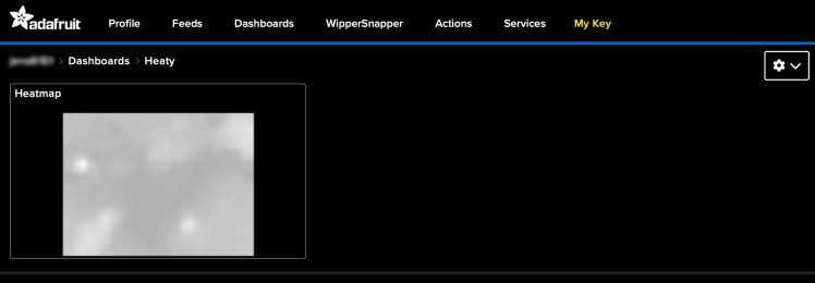
Send Sensor Data as PNG images
As a possibility to collect sensor data without an SD card, I tried to integrade LodePNG (I knew it from PC development and did not do a lot research to know in advance that it consumes a large amount of memory) to convert the 24*32 pixel heat map into a greyscale png to upload it to adafruit.io and store it there for further use. I found out that the algorithm underlying pngs (zlib) takes few memory to decode, but megabytes of memory to encode. Most of the memory is used for pre-building a hash map used for the compression. I reduced it and reduced the window size significantly. Second a lot of memory is used building up a ColorTree that take up a lot of memory per pixel. I reduced that by removing all color channels except one. With these changes the library is likely not useful anymore for re-use, but just fits my needs here.
After conversion to png, I encoded it as base64 and sent it via MQTT.
MQTT
MQTT module follows mainly the simple MQTT sample. I configured it with Adafuit.io which I used as cloud MQTT server. Two things to take care about
- Provisioning of the full certificate chain
- nRF9160 does not support parallel handshakes
The Memfault SDK uses the full certification chain, so I did the same for the adafruit.io. I decided to commission them at startup before activating the modem. So you do not need to provision them manually in advance with the cost of some flash memory. The certificates can be retrieved with the following command.
- openssl s_client -showcerts -connect io.adafruit.com:8883
There is a comment about the ssl handshakes limitation here. I did not find it in the documentation. When multiple modules react on the same event this easily happens though.
Homebridge
I used a Homebridge installation on my local PC to convert MQTT topics into smart devices that appear into the Homekit app on the iOS/MacOS. It runs on top of node and can be easily setup by (see full instructions)
- sudo npm install -g --unsafe-perm homebridge homebridge-config-ui-x
- sudo hb-service install
The plugin Homebridge Mqttthing can connect to MQTT topics and the plugin Homebridge Motion Switch can send push messages. Only a few messages can send push messages. Temperature sensors for example cannot. The trick is to create a rule like if temperature is below 23 °C then activate the motion switch. It is a workaround, but easy and works well.
The homebridge installation and configuration is not part of the repository. Setup and configuration is straight forward.
2022-05-10: Unfortunately the Homebridge setup stopped working, likely due to updates of MacOS and/or iOS or some unintended change to the OS. I can see Homebridge is advertising on the network, but HomeKit is not able to connect anymore.
Companion App
I decided to write a flutter app with the library flutter_blue to handle bluetooth and graphic for rendering the heat map as I wanted to run it both on my development Mac and phone.
There were quite a few (tedious) issues to get the build and application running on a mac.
- Use the latest version of flutter_blue from github
- I needed to manually raise the platform target to 11.5 inside macos/Podfile, clean and rebuild
- Android Studio must be started from command line by "open /Applications/Android Studio.app", otherwise the PATH gets messed up and CocoaPod will fail to install dependencies
- To start an app from the home screen and not via Android Studio, you need to run "flutter run --release" to install the app onto your phone
- Manually give Bluetooth permissions to your application via Settings -> Security and Privacy -> Bluetooth
- For some reason, starting the app on MacOS from Android Studio e.g. for debugging, the Bluetooth rights are not granted. But if you start the app via Finder double click it works. Therefore start the app via Finder, leave it open in the background and start another instance from Android Studio.
It is a one screen app providing buttons for managing the connection, a slider for setting the interval and a plot to display the heat map. The Provider package is used to connect data to the screen.
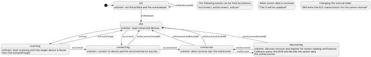
All logic for handling the Bluetooth connection, service and characteristics discovery and data handling is inside BleStatemachine.dart. It uses a state machine I manually implemented with the following logic.
- There are states that have an action on entry and exit.
- There are events that trigger transitions or actions while residing within a state. An action can be attached to a transition.
The companion app logic works as described by the following state diagram.
Side Project Data Collector
I reused several modules and added a SD card module and Camera module to periodically take a heat map reading with a camera reading and save it to SD card. They are connected via events and the architecture is the same. To track filenames over re-boot a counter is persisted via the settings subsystem. Later I added the possibility to set the time via BLE service. As the main project is about the Thingy:91 (and time is short) I will not go into detail. Source code is available in the repository and schematics are as below.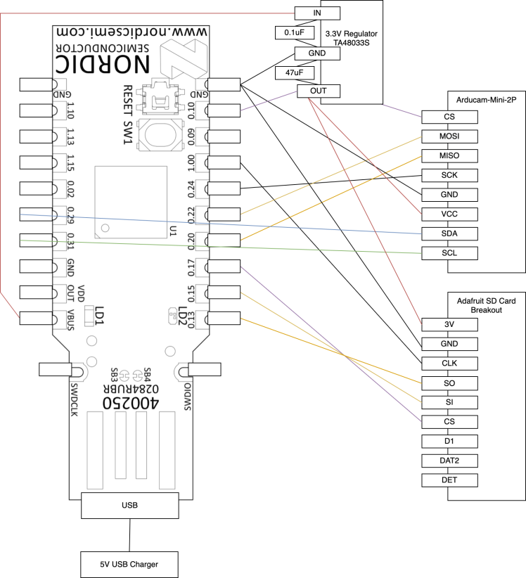
The next steps
- Collect more data and play around with some deep networks (and it if does not work out implement some dump threshold based algorithms)
- Try out the modules on a new project
- Find out why the bluetooth core is unstable, maybe replace it with open thread? Or change the architecture to one business logic core and two network core.
OK the last point sound like eating up time ... let's do something that brings more value with all this ground work learnings.
Licenses
The following licenses can be found in the source code.
- LicenseRef-Nordic-5-Clause - Copyright (c) 2021 Nordic Semiconductor ASA
- Samples, Application and Libraries inside the nRF Connect SDK
- Apache License, Version 2.0 - copyright (C) 2017 Melexis N.V.
- Driver Library for the mlx90640 Sensor
- Apache License Version 2.0 - Adafruit
- Arduino Driver Library for the mlx90640 Sensor (taken as reference)
- Apache License Version 2.0 - Zephyr
- MIT License or LGPL 2.1 (both are stated in the same repo) - Copyright (C)2011-2015 ArduCAM.com
- Driver Library for the ArduCAM (only for the datacollector side project)
- zlib License - Copyright (c) 2005-2022 Lode Vandevenne
- LodePNG'
Thanks for reading to the end or at least scanning though all chapters ;)
Schematics, diagrams and documents
Code
Credits
jens-ajisai
Studied Computational Linguistics with machine learning focus and Japan Studies. Working on AOSP (Android) in the automotive industry. Worked for several HMI and speech related projects. As a hobby working with sensors and microcontrollers, mainly with nRF @ Zephyr or Arduino compatible MCUs. Outside the engineering world I ride bicycle or take photos of plants and animals. The flower on the avatar is a Hydrangea. It blooms around June.
Related products


Leave your feedback...