
Internet Connected Patient Monitoring With Cellular Iot

Made by arunvarghese / Artificial intelligence / Health / Sensors / Wearables / IoT
About the project
Transforming healthcare using IoT, advanced sensors, machine learning, and RTOS for global, efficient, and continuous patient monitoring.
Project info
Difficulty: Difficult
Platforms: Seeed Studio, STMicroelectronics, Twilio, Edge Impulse, Blues Wireless
Estimated time: 4 days
License: Apache License 2.0 (Apache-2.0)
Items used in this project
Hardware components

Story
In the dynamic landscape of healthcare technology, continuous progress is being made to enhance patient care. Integrating telemedicine, artificial intelligence (AI), and robotic surgeries has brought about transformative changes. A pivotal development in this evolution is the creation of an internet-connected patient monitor, poised to revolutionize critical care units by providing remote access to real-time vital signs. This innovation empowers medical professionals to make crucial decisions, regardless of their physical location.
Critical care units serve as the frontline for managing severely ill patients, relying on patient monitoring devices to provide real-time data on vital signs. While these devices are instrumental in diagnosing critical conditions and ensuring patient safety, a significant limitation lies in the constrained accessibility of vital signs data. The geographical distance of attending physicians can impede swift decision-making, especially in cases requiring immediate expert intervention.
The internet-connected patient monitor stands out as a groundbreaking solution, utilizing advanced components such as the STM32F429ZI microcontroller and Blues Notecard. This system establishes a seamless connection between patient vitals and medical practitioners globally.
Technical Architecture
1. STM32F429ZI Microcontroller: As the central processing unit, it collects and processes patient vital signs.
2. Blues Notecard: The Blues Notecard provides crucial internet connectivity, facilitating secure data transmission to a cloud-based visualization dashboard.
3. Visualization Dashboard: Authorized medical personnel access real-time patient data through this dashboard, where raw data is transformed into easily understandable visualizations.
How does the system work?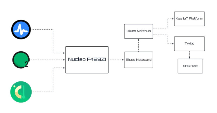
We developed an advanced system functions as an internet-connected patient monitor, featuring a central hub comprised of an STM32F429ZI microcontroller and a Blues Notecard, which collectively serve as the core components. Connected to the STM32F429ZI are various sensors, including a SpO2 sensor, temperature sensor, and ECG sensor, all geared towards monitoring critical patient metrics. Additionally, a finger probe equipped with a Xiao NRF Sense running a TinyML model is integrated to monitor patient movements and promptly identify anomalous behaviours, such as seizures, while also providing a means for patients to request nursing assistance.
The entire system operates on a real-time operating system (RTOS), ensuring seamless coordination between different sensors and the finger probe. The Blues Notecard, known for its efficiency, acts as the conduit connecting this system to a dashboard. This enables immediate visualization and continuous monitoring of vital signs, proving especially valuable in critical situations or when medical professionals are not physically present.
Crucially, the system incorporates an alert mechanism triggered by rapid fluctuations in vital sign readings, indicating potential medical complications. Upon surpassing predetermined thresholds, the system promptly notifies doctors and nurses. Moreover, it is designed to detect seizures or irregular movements. In such instances or when a patient signals for nursing assistance, an alert is sent directly to the nurse.
The impact of this system on critical healthcare is profound. It ensures continuous and real-time monitoring of patients' vital signs, providing an additional layer of care, particularly when immediate medical staff availability is not guaranteed. Its capability to detect anomalies, signal for help, and deliver timely alerts significantly enhances patient safety and outcomes, particularly in high-risk scenarios.
So let's see the main components of this project.
Blues Notecard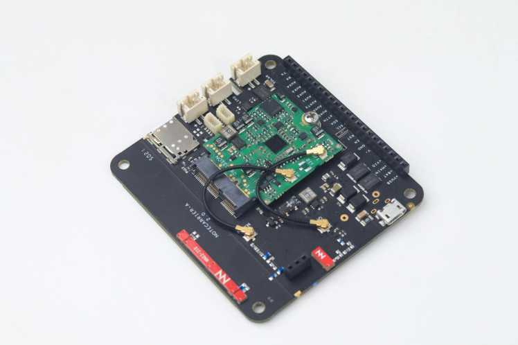
In this project, the Blues Notecard plays a crucial role in establishing continuous and reliable connectivity between physical devices and the Kaa IoT platform. This seamless connection is achieved through low-power cellular technology, ensuring real-time data transmission. The Notecard simplifies the process by automatically sending data continuously to the Kaa IoT platform through the secure cloud service, Notehub.
Key Features Simplified:
1. Connectivity Options:
- Leveraging low-power cellular technology, the Notecard provides versatile connectivity options, creating a robust link between physical devices and the Kaa IoT platform.
2. Continuous Data Transmission:
- The Notecard ensures uninterrupted data transmission by continuously sending information to the Kaa IoT platform. This continuous flow of data enables real-time monitoring and analysis.
3. User-Friendly API:
- Utilizing JSON requests and responses, the Notecard API simplifies the development process. Developers can interact with the system effortlessly, eliminating the need for cryptic AT commands.
Notecarriers for Quick Start:
Notecarriers, specialized development boards, expedite the integration of the Notecard into this IoT project:
Variety of Options: Notecarriers are available in diverse designs, catering to different project needs.
Onboard Features: Many Notecarriers include essential features such as cellular and GPS antennas, along with a USB port for Serial access to the Notecard.
Notehub for Seamless Cloud Integration:
Notehub, the secure cloud service, seamlessly integrates with the Notecard to facilitate continuous data transmission to the Kaa IoT platform:
Continuous Data Flow: Notehub ensures a constant and secure flow of data from the Notecard to the Kaa IoT platform, supporting the need for continuous monitoring in the Telemedicine IoT project.
Fleet Management Console: Notehub provides a user-friendly console for efficient fleet management, allowing easy monitoring and control of multiple Notecard-equipped devices.
Secure Connectors: Secure connectors within Notehub guarantee the secure and reliable routing of data to third-party cloud applications, specifically to the Kaa IoT platform in this scenario.
The Power of a Note:
A Note represented as a JSON object, remains the primary means of sending and receiving data. This developer-friendly approach ensures streamlined and continuous communication between the Notecard, Notehub, and the Kaa IoT platform.
Note: The Blues team has very well-writtendocumentationfor getting started with Notecard.
STM32 Nucelo-144 F429ZI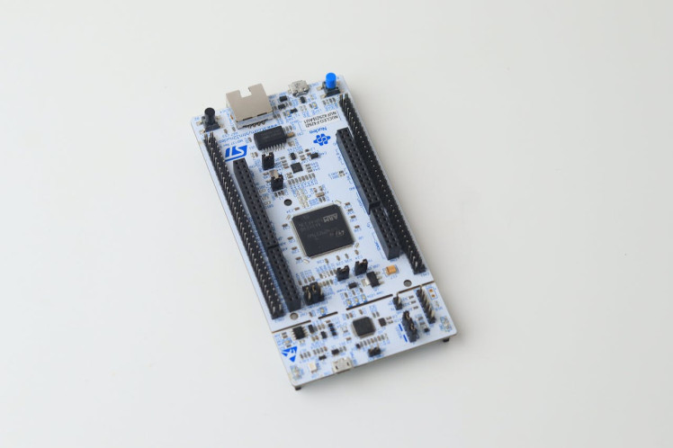
The STM32 Nucleo-144 F429ZI microcontroller is a powerhouse that underpins the Telemedicine IoT project's data processing and sensor integration. Here are some technical points about the STM32 Nucleo-144 F429ZI that are relevant and can be utilized in this Telemedicine IoT project
- Microcontroller Power: The STM32 Nucleo-144 F429ZI is powered by an ARM Cortex-M4 core with FPU, providing ample processing power for real-time data processing and analysis
- Analog-to-Digital Converter (ADC): The built-in ADC allows for precise analog data conversion, enabling accurate capture of sensor readings from the SPO2 and ECG sensors.
- Digital Signal Processing (DSP): The Cortex-M4's DSP capabilities can be harnessed to perform real-time signal processing on ECG waveforms, enhancing the accuracy of heart rhythm analysis.
- GPIO Pins: The numerous GPIO pins provide flexibility for interfacing with various sensors, LEDs, and other components.
- Communication Interfaces: Utilize communication interfaces such as UART, SPI, and I2C to interface with Blues Notecards and sensors. I2C could be used to interface with the Notecard for efficient data exchange
- FreeRTOS Support: The STM32 Nucleo platform supports the FreeRTOS real-time operating system, which can enhance multitasking and real-time data processing capabilities.
- Flash Memory: The microcontroller's Flash memory can store firmware, configuration data, and calibration parameters for sensors, ensuring reliable operation across power cycles.
- Floating-Point Unit (FPU): Utilize the FPU for efficient floating-point arithmetic, enabling accurate calculations in real-time sensor data analysis.
- Development Environment: The STM32 Nucleo board is supported by both STM32Cube software and Arduino IDE
- Debugging Tools: Leverage built-in debugging tools like ST-Link for real-time debugging and performance analysis, enabling efficient troubleshooting during development.
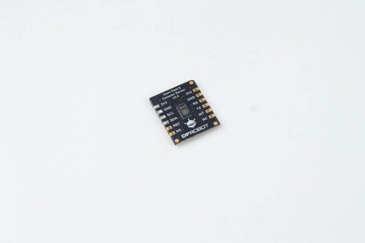
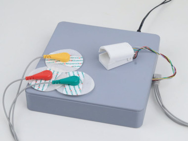
DF Robot MAX30102 PPG Heart Rate and Oximeter Sensor significantly enhance the telemedicine project's diagnostic capabilities. The DFRobot heart rate and oximeter sensor integrate the Maxim MAX30102 chip and an MCU with the heart rate and oximetry algorithm. The MAX30102 uses PPG(PhotoPlethysmoGraphy) to measure data, which will be converted into heart rate and oximetry values when processed by the MCU, then output through I2C or UART, making the sensor easy to use and greatly reducing resource occupation of the main controller.
I2C is used here to communicate with the controller. MAX30102 has an on-chip temperature sensor that is used to compensate for the changes in the environment and to calibrate the measurements. This is a reasonably precise temperature sensor that measures the ‘die temperature’ in the range of -40˚C to +85˚C with an accuracy of ±1˚C. This is used for measuring the patient's temperature so we don't need to add extra sensors for temperature measurement.
Analog Heart Rate Monitor Sensor (ECG)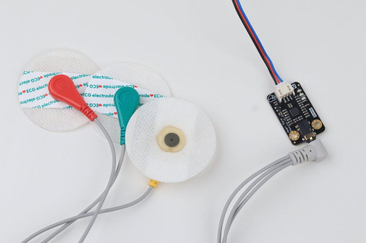
The DFRobot Heart Rate Monitor Sensor is used to measure the heart's electrical activity. This electrical activity can be charted as an ECG and output as an analog reading.
The main advantage of the ECG sensors is that they capture the entire ECG waveform, including P, QRS, and T waves, which are essential for diagnosing various cardiac conditions. This level of detail is not typically available from PPG sensors like the MAX30102, which focuses on extracting heart rate and oxygen saturation from blood perfusion changes.
The problem with the ECG signal is that it can be extremely noisy so they included an AD8232 chip which will generate a clear signal from the PR and QT Intervals.
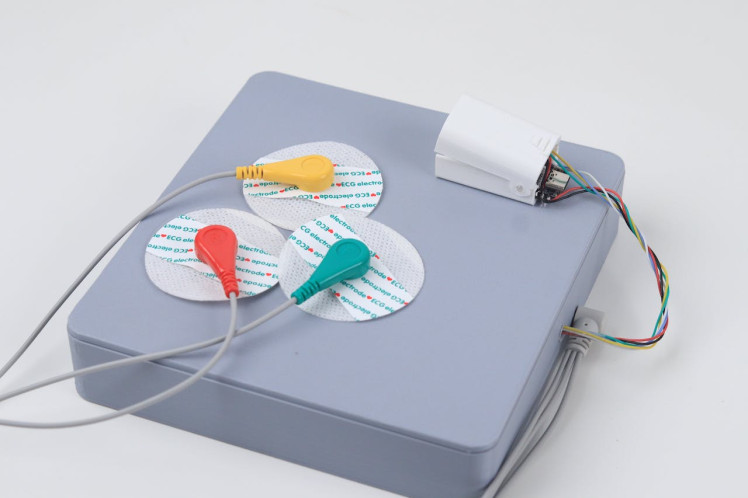
The leads of the ECG in this project will be put into the right arm, left arm and right leg.
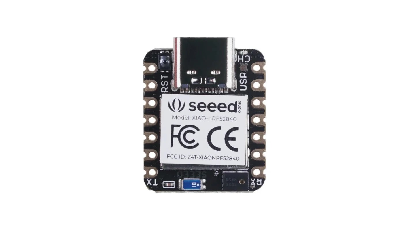
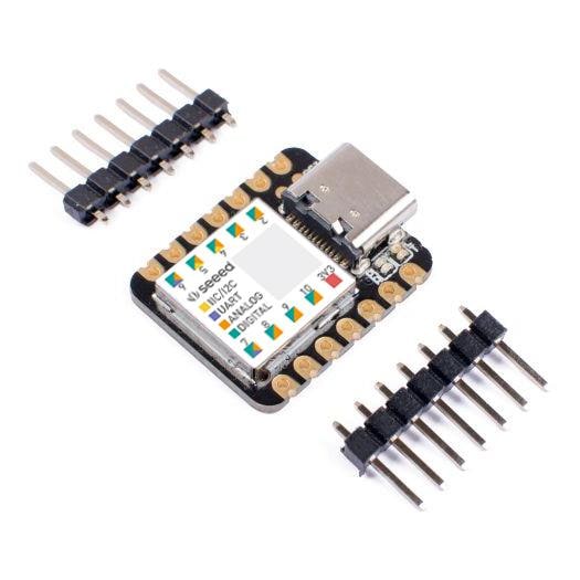
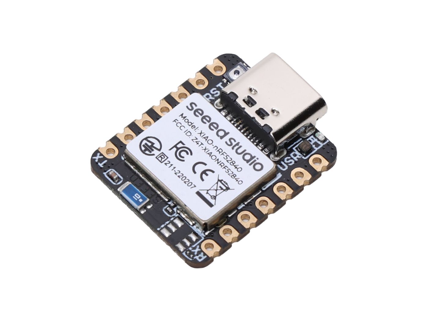
Seeed Studio XIAO nRF52840 Sense in Machine Learning Integration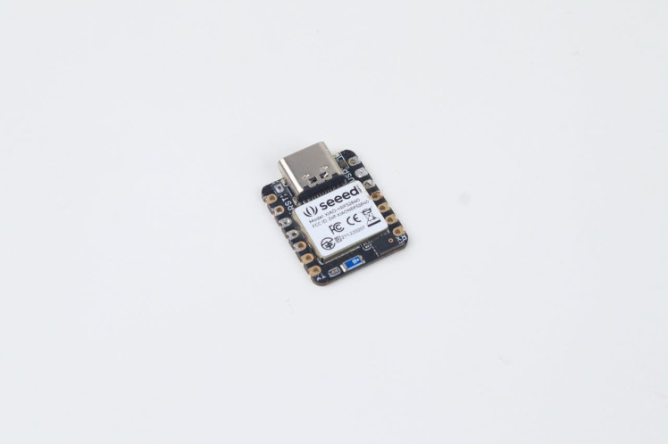
The Seeed Studio XIAO nRF52840 Sense, equipped with Bluetooth 5.0 wireless capability and low power consumption, serves as a powerful tool for embedded Machine Learning projects. Its small form factor makes it ideal for integration into a finger probe, facilitating continuous data transfer to the STM32 upon detecting movements.
Utilizing the onboard LSM6DS3 accelerometer on the XIAO nRF52840 Sense, Edge Impulse enables motion recognition. The integrated TinyML model can detect various states, including Idle state, Hand Raise (for calling Nurse) and Anomalous motion.
Data Acquisition
As we all know machine learning starts with the data. The following simplified process outlines data acquisition for training the TinyML model using Edge Impulse.
1. Upload the provided code to the XIAO, capturing accelerometer data using the LSM6DS3 sensor.
#include "LSM6DS3.h"
#include "Wire.h"

LSM6DS3 myIMU(I2C_MODE, 0x6A);  //I2C device address 0x6A

#define CONVERT_G_TO_MS2 9.80665f
#define FREQUENCY_HZ 50
#define INTERVAL_MS (1000 / (FREQUENCY_HZ + 1))
static unsigned long last_interval_ms = 0;

void setup() {
	Serial.begin(115200);
	while (!Serial);
	if (myIMU.begin() != 0) {
	Serial.println("Device error");
	} else {
	Serial.println("Device OK!");
	}
}
void loop() {
	if (millis() > last_interval_ms + INTERVAL_MS) {
	last_interval_ms = millis();
	Serial.print(myIMU.readFloatAccelX() * CONVERT_G_TO_MS2, 4);
	Serial.print('t');
	Serial.print(myIMU.readFloatAccelY() * CONVERT_G_TO_MS2, 4);
	Serial.print('t');
	Serial.println(myIMU.readFloatAccelZ() * CONVERT_G_TO_MS2, 4);
	}
}
2. Then start the data forwarder using the command `edge-impulse-data-forwarder`.
3. Then connect the XIAO to Edge Impulse through the CLI, providing Edge Impulse account credentials.
4. In the Data collection tab, collect and split data for Hand Raise and Idle states, ensuring a balanced dataset. The more data you have the better your model becomes.
Data Collection Tab

Data Collection Tab
ImpulseDesign
Impulse stands for machine learning pipeline in Edge Impulse which is used for feature generation which is a key thing in Machine Learning.
Although neural networks are fantastic, they have one major problem. They're useless when it comes to dealing with data they've never seen before (like a new activity). Because neural networks only have access to training data, they are unable to assess this. Even if you offer it something entirely different beyond what it's seen before, it'll still fall into one of the four categories. So we also added an anomaly block.
This is the impulse which is made for this project. You can either follow it or make your own according to your data.
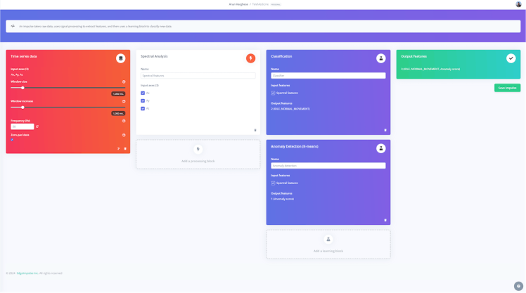
After saving the impulse, I generated the features for this data by moving to the feature generation tab.
Various parameters for feature extraction

Various parameters for feature extraction
This feature explorer next to the parameters window shows the features extracted from the data we have given.
Generated features

Generated features
Model Training& Testing
During model training, the neural network adjusts its weights and biases to find the optimal configuration for a machine learning task, aiming to minimize a loss function.
In the NN Classifier tab, under Impulse Design, you can tweak different parameters that impact the training of the neural network. I've adjusted the default values in the image to enhance accuracy.
The trained model has an accuracy of 95%, which would suffice for our needs
Neural Network Settings

Neural Network Settings
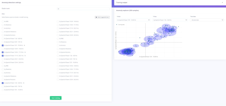
In the anomaly detection settings, I have selected the suggested axis and trained the model to detect the anomalies.
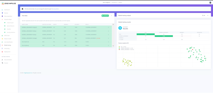
Once the model is trained, we can now test it to see how it performs with new data. Select Classify All under Model Testing. The model's performance on our testing data is displayed in the Model testing results tab. Our accuracy is 98.3%, which is still awesome.
Deployment
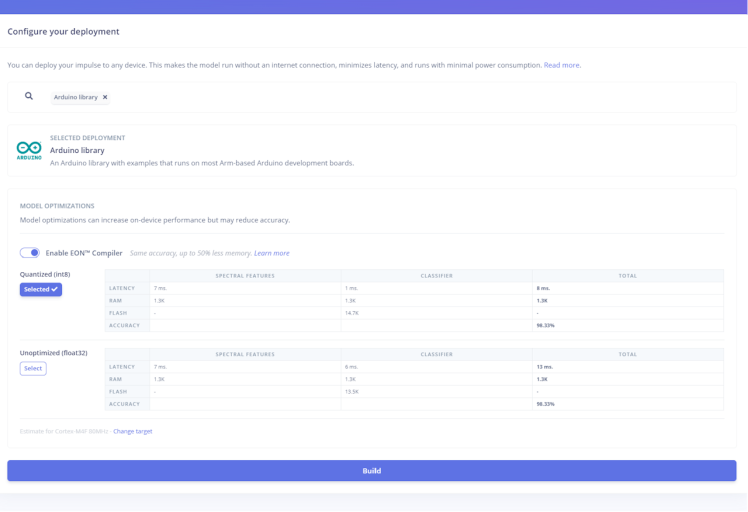
Then I opted for the Arduino library as the method of deployment to the XIAO. A quantized version of the model is downloaded due to the memory constraint.
To facilitate data transmission from the XIAO to the STM32, the Universal Asynchronous Receiver-Transmitter (UART) method was employed. Upon inspecting the datasheet, numerous Hardware serial options for the STM32 Nucleo were identified, with the selection of USART2.
Real-Time Operating System (RTOS)A Real-Time Operating System (RTOS) is a vital software component designed for embedded systems, providing multitasking capabilities. It facilitates the concurrent execution of multiple tasks, each with its priorities and execution times while ensuring deterministic timing behaviour.
Incorporating the Real-Time Operating System into my telemedicine project has brought about a paradigm shift in efficiency and responsiveness. By intelligently segmenting the project into distinct tasks and assigning appropriate priorities, the RTOS ensures the seamless execution of critical functions. Tasks such as SpO2 measurement, ECG reading, XIAO serial data retrieval, and sending data to the cloud are executed without contention, optimizing the overall system performance.
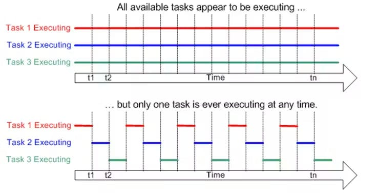
The kernel serves as the core component of the operating system. In the context of multitasking, each program executed is treated as a task or thread under the control of the operating system. While traditional processors can only execute one task at a time, a multitasking operating system, like an RTOS, creates an illusion of simultaneous execution by swiftly switching between tasks. The execution mode of three tasks over time is depicted in the figure below.
Here are some concepts of RTOS.
- Task: A task is a basic unit of execution in an RTOS. Each task represents a distinct activity that runs independently.
- Task Scheduling: The RTOS scheduler determines the order and timing of task execution based on task priorities and scheduling policies.
- Priority Management: Tasks are assigned priorities to control their execution order. Higher-priority tasks preempt lower-priority tasks.
- Semaphores: Semaphores are synchronization mechanisms used to manage access to shared resources among tasks.
- Mutexes: Mutexes are used to provide exclusive access to resources, preventing conflicts and data corruption.
- Queues: Queues facilitate communication between tasks, allowing data to be passed in a structured manner.
In this project, three distinct tasks have been created:
1. Reading ECG data and transmitting it to the cloud.
2. Reading SpO2, heart rate, and temperature, and transmitting the data to the cloud.
3. Reading serial data from the XIAO BLE sense to detect any movements.
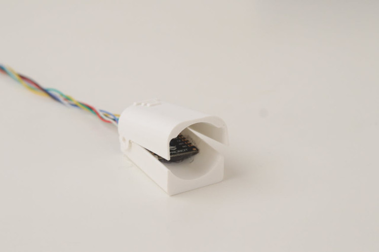
Assembly & ElectronicsThe MAX30102 sensor and the XIAO BLE sense will be attached to the finger clip. So we need a finger clip design in which I can put these things. After long hours of searching, I find a design for this project—great thanks to him.
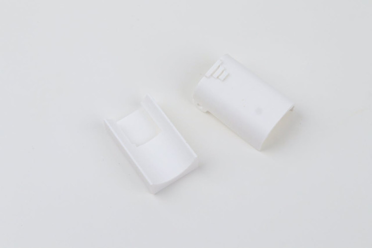
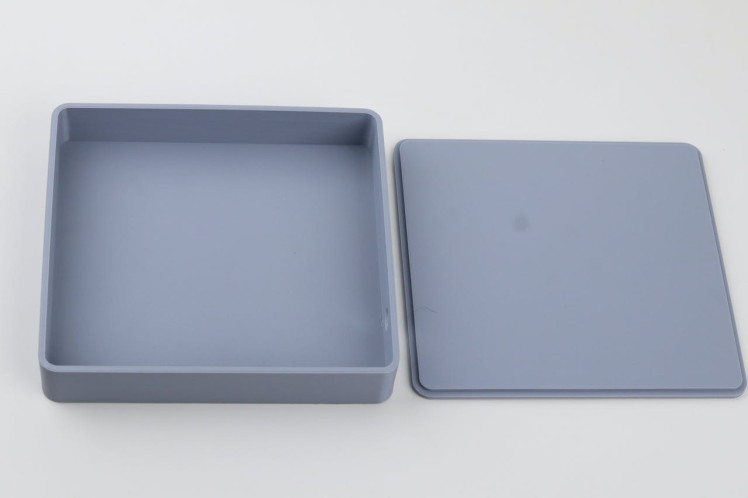
For securing the remaining components I used this 3d printed box.
The MAX30102 and XIAO were attached to the finger probe by pulling out the required wires.

Before getting into the further assembly we can talk about essential electronics needed for this project.
A 12V 3A power supply powers the entire project setup. So we need to power the STM32 Nucleo, XIAO and the Notecard using this power supply. Upon inspecting the data sheets of these elements I concluded that 5V is the best for powering these elements. I decided to use a Mini 360 buck converter for stepping down the 12V voltage to the 5V one so I can power every element with this same power supply.
Mini 360 Step Down Buck Converter

Mini 360 Step Down Buck Converter
These are the input and output voltage ranges of this module.
- Input voltage: DC 4.75V-23V
- Output voltage: DC 1.0V-17V (Adjustable, Output < Input)
Then we secured each component one by one by making connections into it.
Female DC jack for powering the system

Female DC jack for powering the system
Soldered the connections between the finger probe and MCU

Soldered the connections between the finger probe and MCU
Attached the ECG module

Attached the ECG module
Then we checked any remaining connections to be done, the connection between the notecard and the MCU was missing so we also did it.
Finally, the hardware part is ready. It's time to look at the software part.
Building Dashboard With Kaa IoTKaa IoT, a versatile platform for developing and managing IoT solutions, supports a variety of communication protocols to ensure seamless data exchange between devices and the platform. One of the key protocols it accommodates is MQTT (Message Queuing Telemetry Transport), which offers lightweight and efficient communication, making it suitable for real-time monitoring and control applications.
The Kaa IoT platform offers a comprehensive and user-friendly dashboard that serves as a central hub for managing and monitoring IoT devices and applications. The dashboard provides a visual interface through which users can efficiently oversee their connected devices, gather insights, and control various aspects of their IoT ecosystem.
Key features of the Kaa IoT dashboard include:
1. Device Management: The dashboard allows users to view and organize all their connected devices in one place. This includes device status, connectivity information, and data transmission details. Users can easily add, remove, and categorize devices, simplifying the management process.
2. Data Visualization: Kaa's dashboard provides tools to visualize the data generated by IoT devices in real time. This could include graphs, charts, and other visual representations that help users understand trends, patterns, and anomalies in their data streams.
3. Analytics: With built-in data analytics capabilities, the dashboard enables users to perform various analyses on the collected data. Users can gain insights into device performance, usage patterns, and operational efficiency, helping them make informed decisions.
3. Alerts and Notifications: The dashboard can be configured to send alerts and notifications based on predefined conditions or thresholds. This feature ensures timely responses to critical events or deviations from expected behaviours.
4. Device Control: Users can remotely control IoT devices through the dashboard. This might involve sending commands, adjusting settings, or triggering specific actions on connected devices.
5. Security and Access Control: The dashboard supports user authentication and access control mechanisms, ensuring that only authorized individuals can access and manage the IoT infrastructure. This helps maintain data security and privacy
6. Customization: Depending on the specific use case, the dashboard can often be customized to display the most relevant information and features for users, enhancing usability and efficiency.
Connecting a device to the Kaa IoT platform and creating a dashboard involves several steps.
Here's a simplified guide:
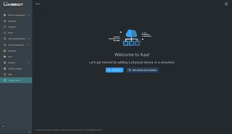
- Go to the Device Management tab in your Kaa Cloud account assuming that you have signed up for one.
- Select the Add device option to start the registration process for a device's digital twin, referred to as an "endpoint" within the Kaa platform.
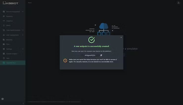
- In the form provide a display name and application description for your application, along with an endpoint token. You have the option to leave the endpoint field blank, in which case Kaa IoT will generate a random token for the device.
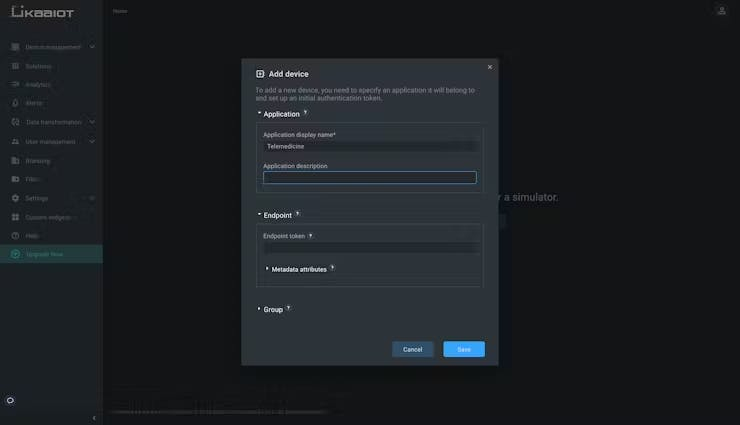
- If the token is generated by Kaa IoT, remember to securely store it, as it's essential for establishing a connection with the platform.
- Now navigate to Device Management - Applications - Your Application - Versions - Your Application ID - v1
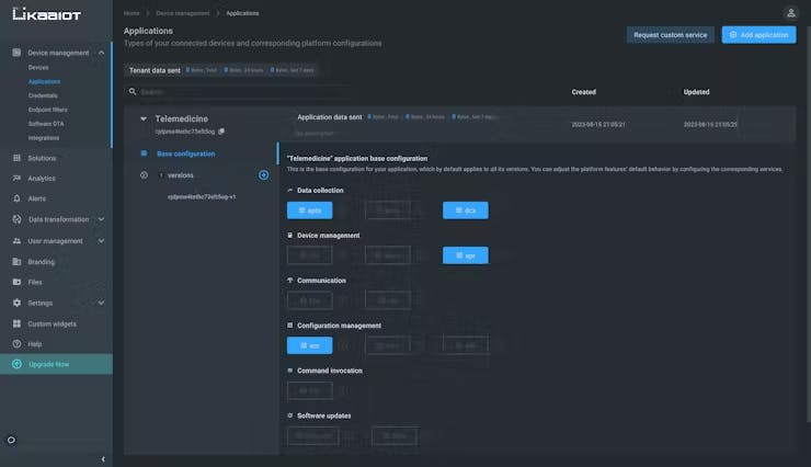
- Select epts set "Autoextract" enabled and save the configuration to proceed.
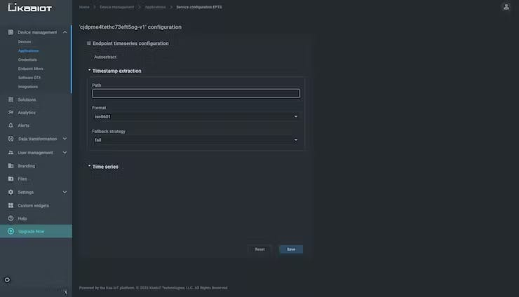
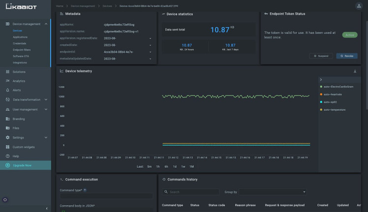
- Load a sample code onto your device that transmits telemetry data to the "epts" endpoint. Next, navigate to Device Management - Devices - Your Endpoint. If you observe a display resembling this, your configuration is successful, confirming your device's successful connection to the cloud.
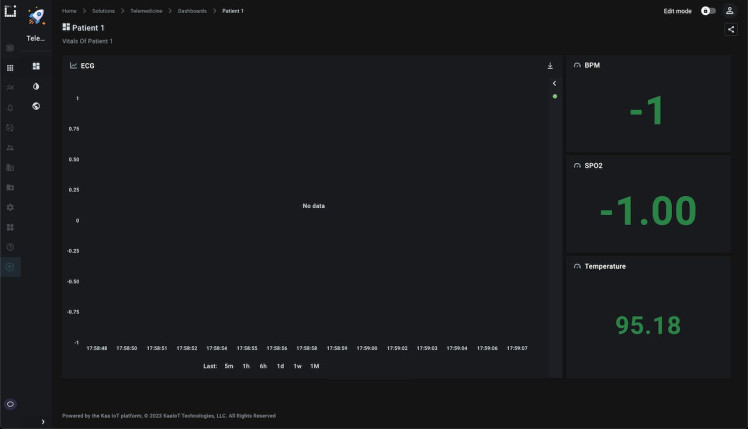
- To create a dashboard move on to Solutions - Your Project - Dashboards. Customize the default 'Home' dashboard by incorporating relevant information. Add relevant widgets and configure them accordingly. This is my dashboard containing all the widgets needed for this project.
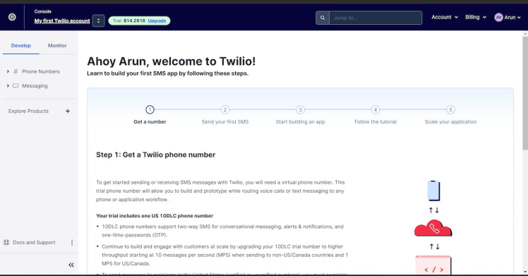
Twilio is a cloud communications platform that provides a set of APIs (Application Programming Interfaces) for building and integrating communication services into applications. It allows developers to add messaging, voice, and video capabilities to their applications without having to build or maintain complex infrastructure.
Here we are using Twilio to send SMS alerts if there are any sudden changes in vitals, if the patient needs nursing assistance or if any anomalous motions of the patient.
Follow these steps carefully for integrating Twilio
1) Signup for Twilio, if you don't have an account
2) Get a Twilio Phone number, this phone number will be used for sending the SMS alert to the concerned person.
3) Then note the account info such as the Account SID, Auth Token, and the generated Twilio number, this should need to be added in the Notehub for sending SMS.
Setting the Routes in NotehubSetting up the route is an easy task, just head over to notehub.io press on the create route option, and select the required service which is in the Routes tab.
In this project mainly three routes are created and their purposes are
1) To send the vitals data to the Kaa IoT platform
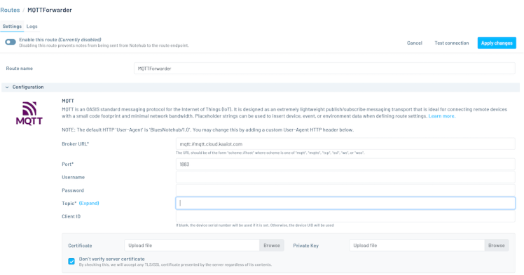
This is the route created for sending the data to the KaaIoT. For proper data forwarding, we need to provide the Broker URL, Port Number, and Topic.
The general MQTT topic structure for endpoint-originated requests will be like this.
kp1/{application_version}/{extension_instance_name}/{endpoint_token}/{resource_path}where:
kp1is the reserved prefix for the Kaa Protocol version 1.{application_version}is a unique name that identifies the application version that the request-originating endpoint operates.{extension_instance_name}is a name that uniquely identifies an extension service instance the message is destined to. ecr is used here as the extension name.{endpoint_token}is an endpoint token that uniquely identifies the endpoint{resource_path}as an extension-specific resource path that exposes some IoT functionality to the endpoints. JSON is the resource path used here.
This is the configuration settings and when you scroll down you will see the filters section, you need to select the notefile that you are sending.
2) To alert the nurse if the patient behaves anomalously or to call for assistance.
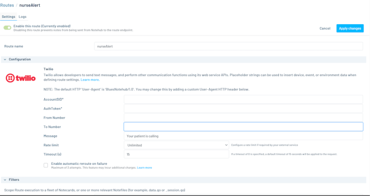
This is the route created for sending the alert to the KaaIoT. For proper data forwarding, we need to provide the Account SID, Auth Token, From Number, and To Number. All these are available on your Twilio website.
3) To alert the doctor if there are any sudden changes in vitals.
In this case, also same Twilio route will be created but with a different notefile and message.
WorkingHere are some screenshots for the proof of work.
 Live data of the patient1
 SMS alert for nursing assistance
 SMS alert to the doctor showing the vitals are getting low.
Schematics, diagrams and documents
Code
Credits
Related products


Leave your feedback...