
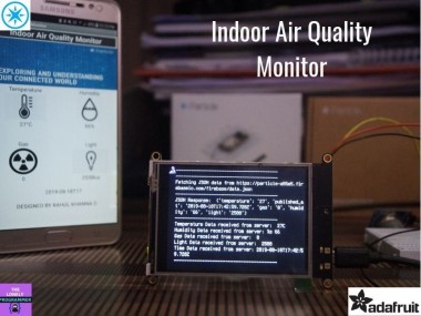
Indoor Air Quality Monitor

Made by the lonely programmer / Displays / Environmental Sensing / Health / Productivity / Sensors
About the project
Measuring air quality within a particular region in real-time is an effective way to prevent the unhygienic situation.
Items used in this project
Hardware components


Story
Why Did We Build This?
More than two billion people worldwide continue to depend on solid fuels, including fuels and coal, for their energy needs. Cooking and heating with fuels on open fires or traditional stoves result in high levels of indoor air pollution. Indoor smoke contains a range of health-damaging pollutants, such as small particles and carbon monoxide, and particulate pollution levels maybe 20 times higher than accepted guideline values.
The following people are more likely to be affected:
- People with asthma
- People with lung disease
- People with cardiovascular disease
Also, exposure to high levels of air pollution over longer periods (in months) may be linked to adverse pregnancy outcomes such as reduced birth weight or preterm birth.
We hereby come up with a solution to measure the indoor air conditions and to display the status to the user with GUI.
Hardware Build
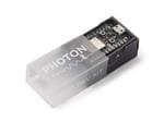
First of all, I would like to thank Particle for supporting this project with the Argon Kit, I felt informative using this board and able to learn IoT with its easy interface.
You can purchase the Argon KIT for $35 from Particle store.
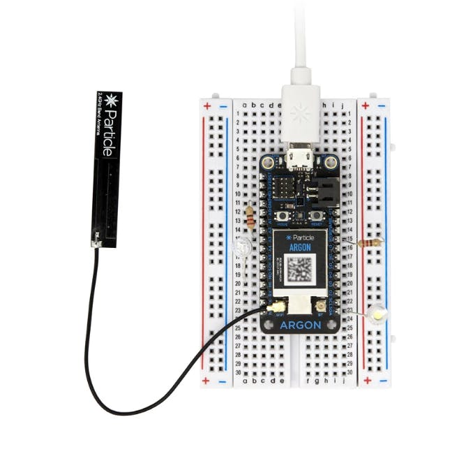
Step 1: Getting Started with Argon Kit (Content from Particle)
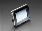
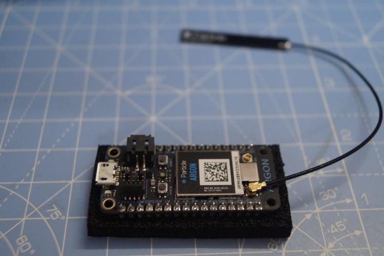
The Argon is a powerful Wi-Fi enabled development kit that can act as either a standalone Wi-Fi endpoint or Wi-Fi enabled gateway for Particle Mesh networks. It is based on the Nordic nRF52840 and has built-in battery charging circuitry so it’s easy to connect a Li-Po and deploy your local network in minutes.
The Argon is great for connecting existing projects to the Particle Device Cloud or as a gateway to connect an entire group of local endpoints.
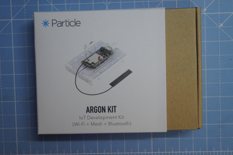
 Argon Kit
Specification:
- Espressif ESP32-D0WD 2.4G Wi-Fi coprocessor -Onboard 4MB flash for ESP32 -802.11 b/g/n support -802.11 n (2.4 GHz), up to 150 Mbps
- Nordic Semiconductor nRF52840 SoC -ARM Cortex-M4F 32-bit processor @ 64MHz -1MB flash, 256KB RAM -IEEE 802.15.4-2006: 250 Kbps -Bluetooth 5: 2 Mbps, 1 Mbps, 500 Kbps, 125 Kbps -Supports DSP instructions, HW accelerated Floating Point Unit (FPU) calculations -ARM TrustZone CryptoCell-310 Cryptographic and security module -Up to +8 dBm TX power (down to -20 dBm in 4 dB steps) -NFC-A tag
- On-board additional 2MB SPI flash
- 20 mixed signal GPIO (6 x Analog, 8 x PWM), UART, I2C, SPI
- Micro USB 2.0 full speed (12 Mbps)
- Integrated Li-Po charging and battery connector
- JTAG (SWD) Connector
- RGB status LED
- Reset and Mode buttons
- On-board 2.4GHz PCB antenna for Thread/BLE (does not support Wi-Fi)
- Two U.FL connectors for external antennas (one for Thread/BLE, another for Wi-Fi)
- Meets the Feather specification in dimensions and pinout
- FCC, CE, and IC certified
- RoHS compliant (lead-free)
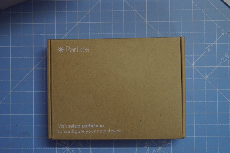
What's inside the Box?
The Kit contains an Argon board, a 2.4Ghz antenna, a USB cable, breadboard, LED, and photodiode.
 1 / 4 • KIT
Step 2: Setting up Argon Kit
Connect the antenna to the Argon board
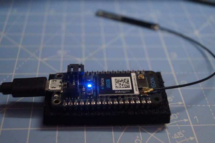
Now connect the USB cable and the Blue LED glows.
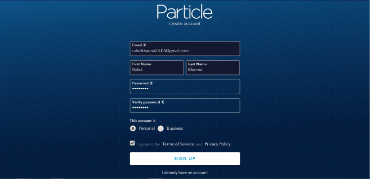
Create a Particle account to register the Argon device.
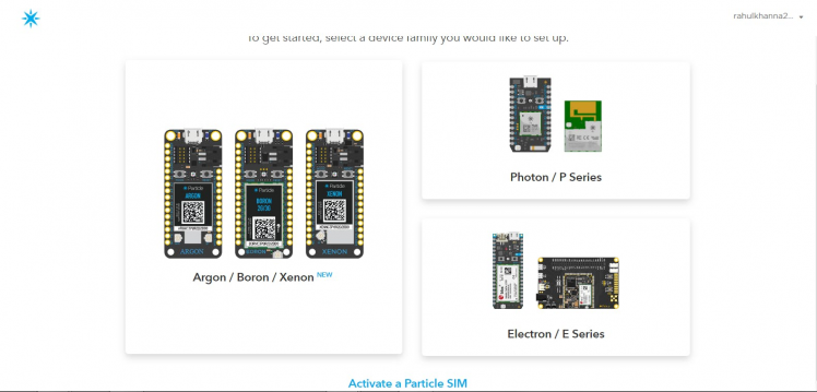
Select the Argon/Boron/Xenon category and select the Argon option.
 1 / 2
1 / 2
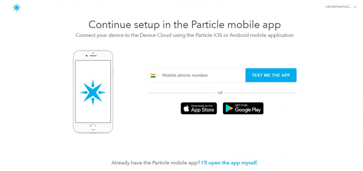
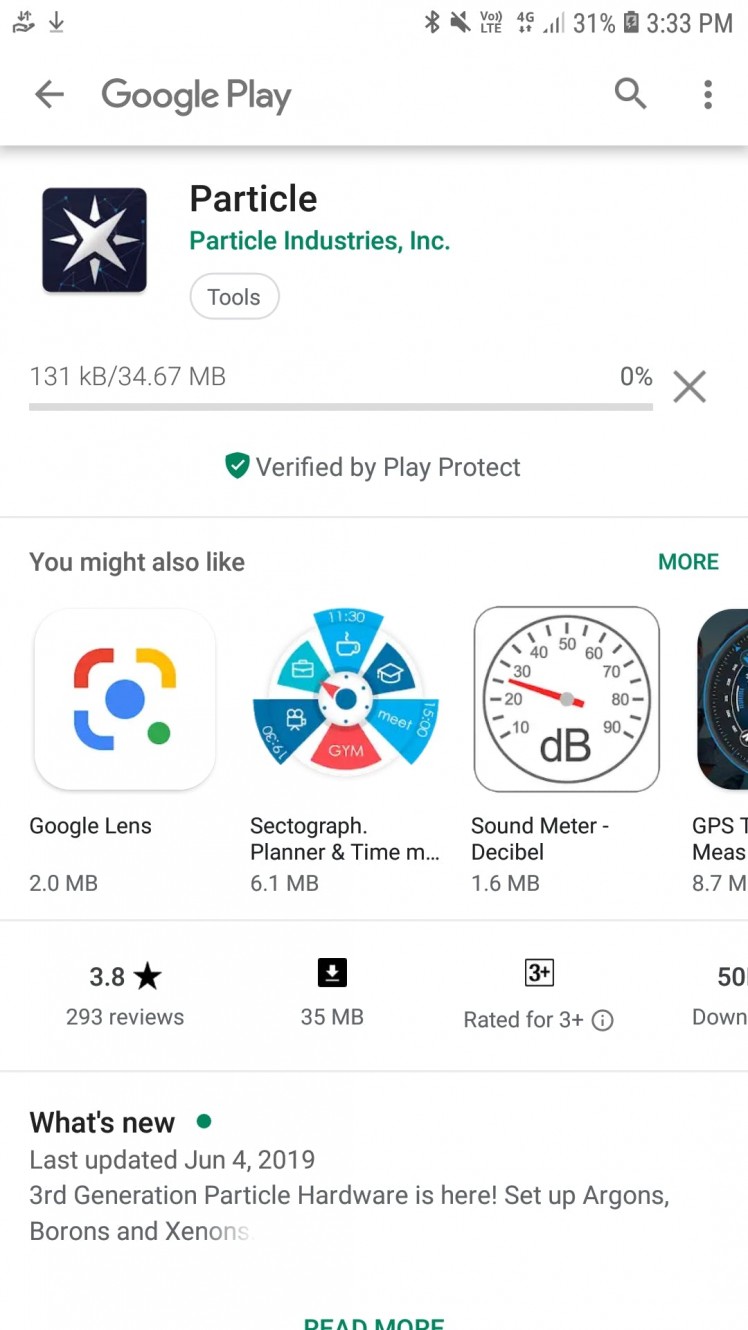
Now download the Particle app from the link. Particle app is available for both Android and iOS.
Connection to the Particle Device Cloud
 Download the Application
Login the Particle account and Press + to add your device.
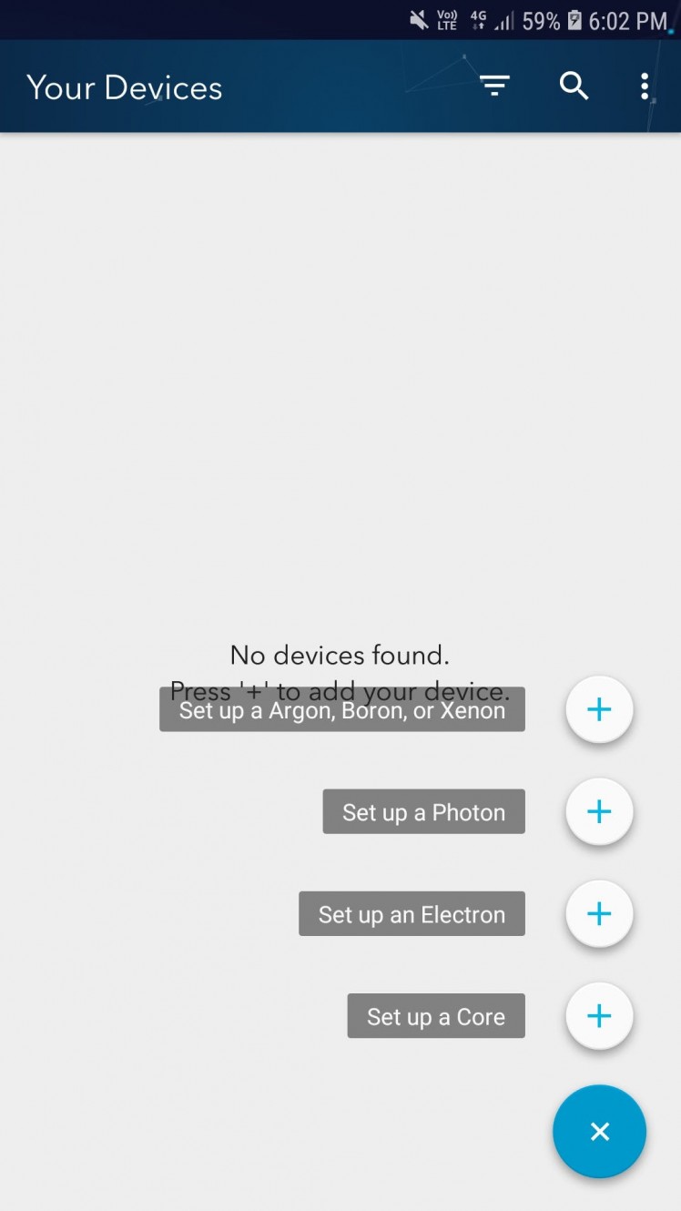
Click on Set up an Argon, Boron, Xenon and Click SCAN STICKER button.
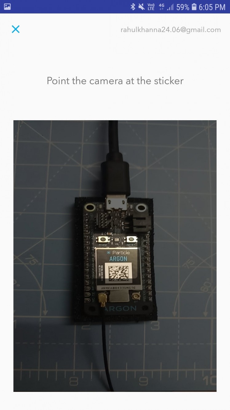
Now scan the QR sticker from the Argon board and the device will be paired with the account.
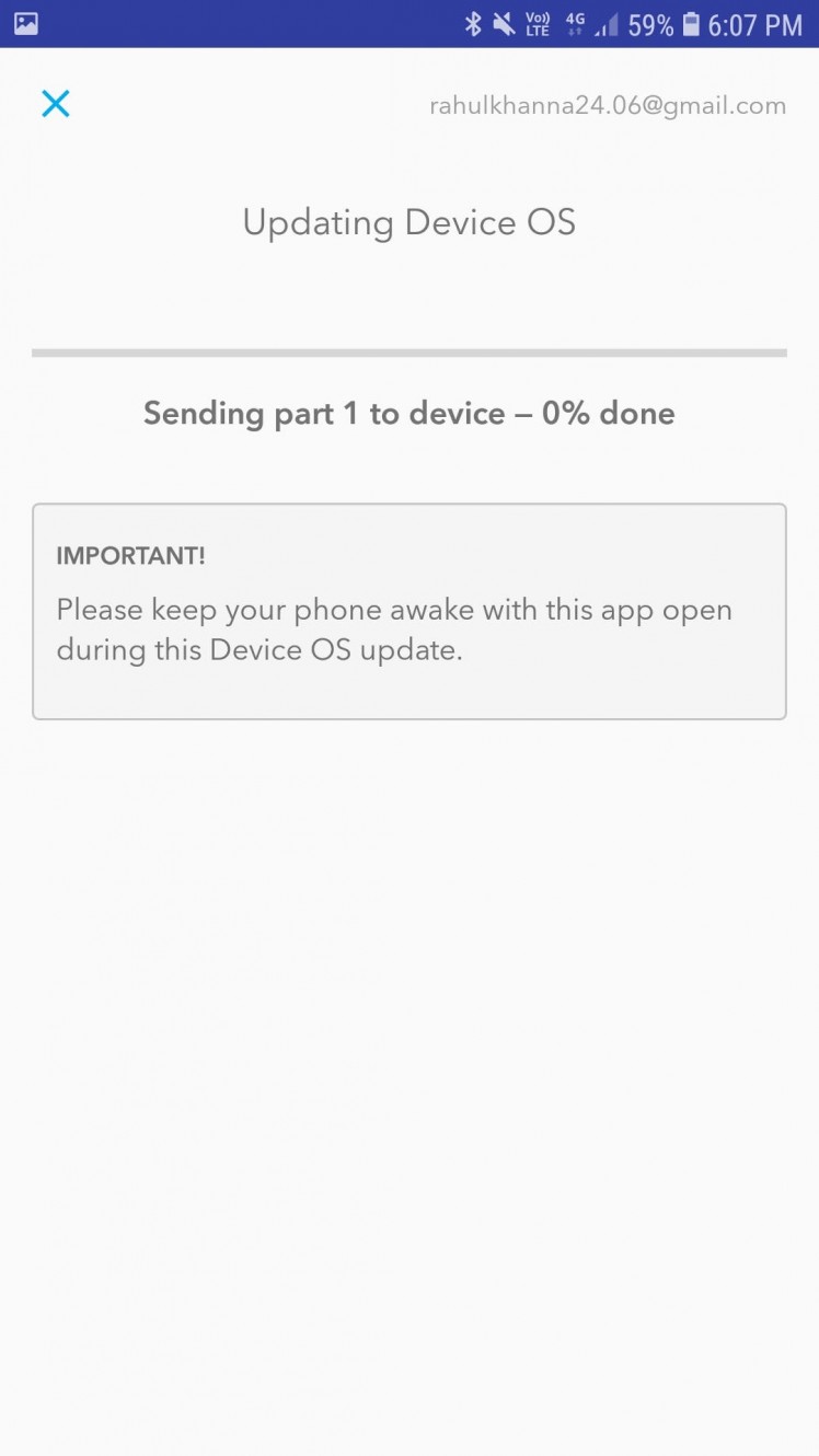
Make sure that the Device OS is updated. If there is an OS update, it is recommended to update it using the app.
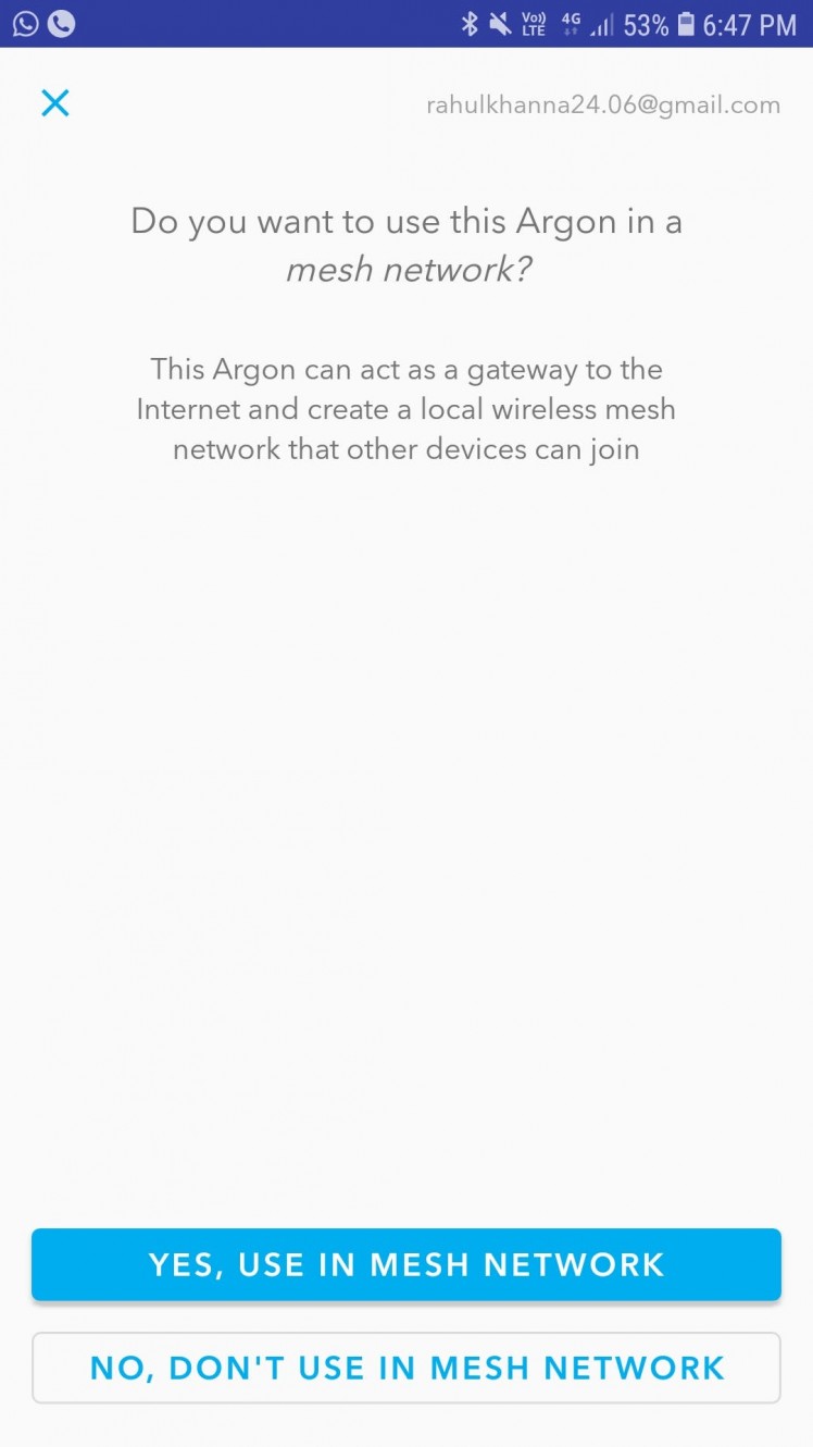
Particle Mesh network configuration
Since we are not making a mesh network for this project, Click No, Don't use in MESH network. For the first 100 devices, the Device cloud is free.
To connect the Argon board to the Device cloud, we will send the Argon Wi-Fi network credentials
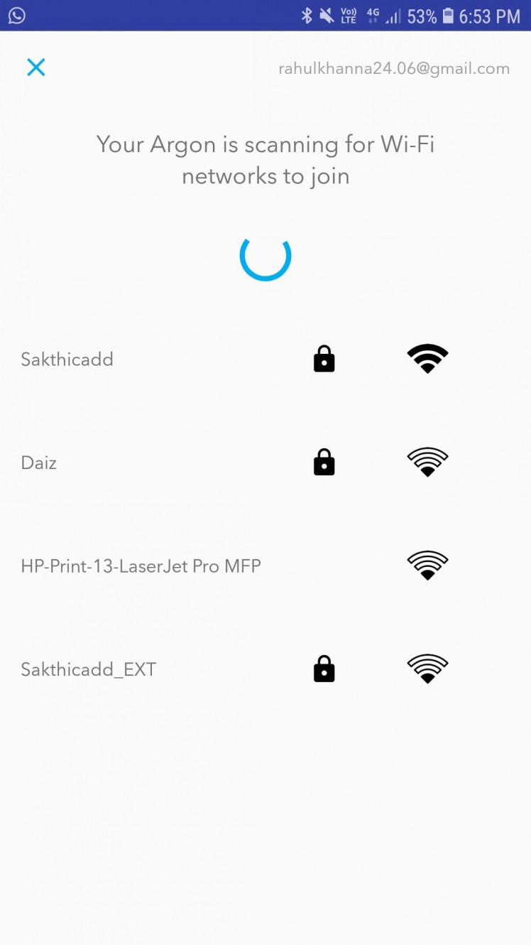
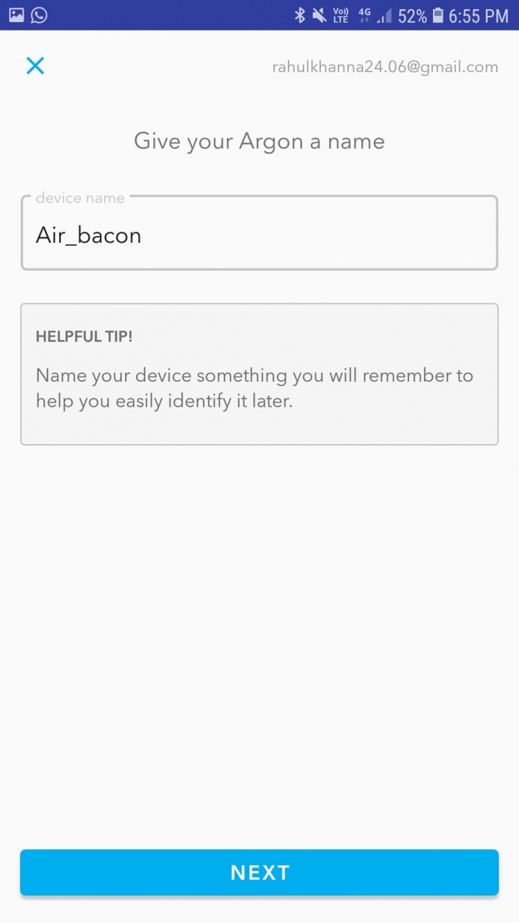
Setting the Wi-Fi credentials, give the Argon a name. Here I've used Air_bacon
Setup is done and we will be able to program the device via over-the-air (OTA).
Step 3: Installing Particle CLI
Download Particle CLI (Command Line Interface) to install the device drivers and DFU-util. Refer the documentation from Particle for installation. https://docs.particle.io/tutorials/developer-tools/cli/

Once the installation is complete, connect the Particle Argon board to the PC.
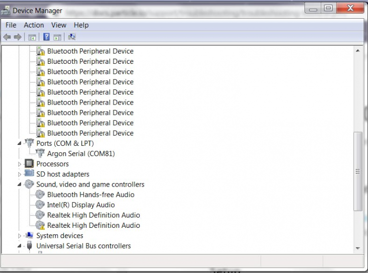
You can find the serial port in the device manager as shown below. (ArgonSerial COM81)
Now open the Particle Web IDE and upload the Serial-test code to the Argon board.
int var = 0;
void setup() {
	Serial.begin(9600);
	Serial.println("Serial port initialized . . . ");
	Serial.println(" **** The Lonely Programmer **** ");
}
void loop() {
   Serial.println(var);
	delay(500);
	var+=1;
}
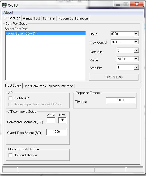
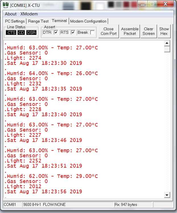
After uploading the code, open any serial terminal with the following config.
In my case, COM81 is opened at BAUD RATE of 9600.
Click the Terminal tab to open the serial port.
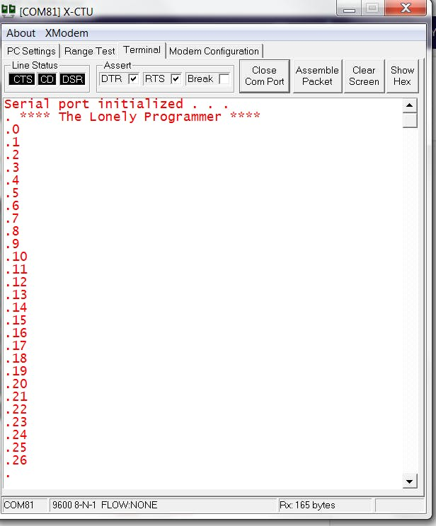
By this Step, we can verify whether the serial port is working properly. This can be used to debug at each section of the code.
Step 4: Interfacing with Argon Kit
We use Web IDE to program the Argon board and upload it via OTA. We can also use the Particle workbench to program the Particle devices.
The Web IDE is one of the ways you can write, compile, and deploy code to your Particle devices.
Click this link to open the Web IDE on your browser.
 Web IDE
Click on Blink an LED on the left side of the page. The code loads on the right pane. The code is very similar to the Arduino programming structure.
 Blink
Blink
The Argon board has three LED. One LED to indicate the charging status and the other two are used for GPIO.
Now we initialize the two LED and we name it as led1, and led2.
int led1 = D0;
int led2 = D7;
Next, we configure the LED's as output
pinMode(led1, OUTPUT);
pinMode(led2, OUTPUT);
In the void loop function, we toggle the LED's alternatively.
void loop()
{
 digitalWrite(led1, HIGH);
 digitalWrite(led2, LOW);
 delay(1000);

 digitalWrite(led1, LOW);
 digitalWrite(led2, HIGH);
 delay(1000);
}
Click the lightning bolt icon on the top left of your screen to flash your code to the device. As soon as you click, the Particle Device cloud will compile the program source code to a binary file and send it over-the-air (OTA) to the Argon. You can find the green LED blinking fast after flashing and the device is updated.
Check this document from the Particle's documentation.
https://docs.particle.io/tutorials/device-os/led/argon/#listening-mode
Step 5: Interfacing Sensors
The Temperature, Humidity, Air Quality, Ambient light, Heat level should be interfaced for this project. So we will see the step by step tutorial to interface with each sensor.
Interfacing DHT11:
The DHT11 sensor detects water vapor by measuring the electrical resistance between the two electrodes. The humidity sensing component is a moisture holding substrate. When water vapor is absorbed by the substrate, the ions are released by the substrate which increases the conductivity between the electrodes. The change in resistance between the two electrodes is proportional to the relative humidity computed. Higher relative humidity(RH) decreases the resistance between the electrodes, while lower relative humidity increases the resistance between the electrodes i.e Relative humidity is inversely proportional to the resistance between two electrodes.
Here we connect the DHT11 temperature and humidity sensor to the digital pin of the Argon board.
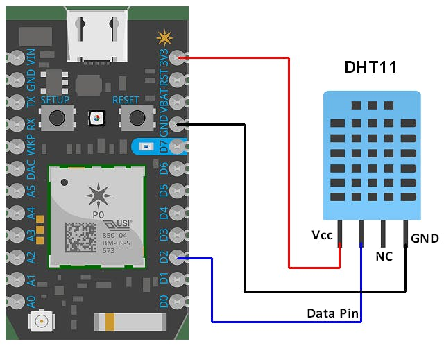
The analog pin D2 of Argon is used for the output signal.
Connections:
Argon ------------------------------------- DHT11
VCC(3.3v) -> Vcc(3.3v)
GND -> Ground(0V)
D2-> Signal
The Temperature and the humidity from the DHT11 are calculated and stored in the variables which will be carried to the next section of the project.
 DHT11
DHT11
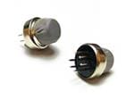
Interfacing Air Sensor:
Here I interface MQ5 gas sensor which is a generic gas sensor available in the market which is more suited to detect and determine LPG concentrations.
This module has two output possibilities
- The analog output can be used to detect Gas leakage and to measure the volume of Gas leakage using certain algorithms which are implemented in the firmware and the level of Gas leakage is specified in ppm.
- The digital out can be used to detect Gas leakage. When there is a leakage of gas, an Interrupt is set by the Arduino which indicates the leakage of gas.
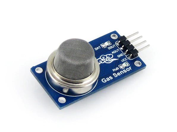
The digital pin D3 of Argon is used for the Output signal.
Connections :
Argon ------------------------------- MQ5
VCC(3.3v) -> Vcc(3.3v)
GND -> Ground(0V)
D3 -> Data
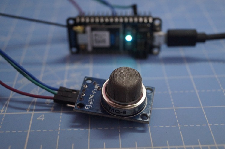 MQ6
MQ6
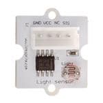
Interfacing Light Sensor:
LDR is a Light Dependent Resistor. LDRs are made from semiconductor materials to enable them to have their light-sensitive properties. There are many types but one material is popular and it is cadmium sulfide (CdS). These LDRs or PHOTO RESISTORS works on the principle of “Photo Conductivity”. Now what this principle says is, whenever light falls on the surface of the LDR (in this case) the conductance of the element increases or in other words, the resistance of the LDR falls when the light falls on the surface of the LDR. This property of the decrease in resistance for the LDR is achieved because it is a property of semiconductor material used on the surface.
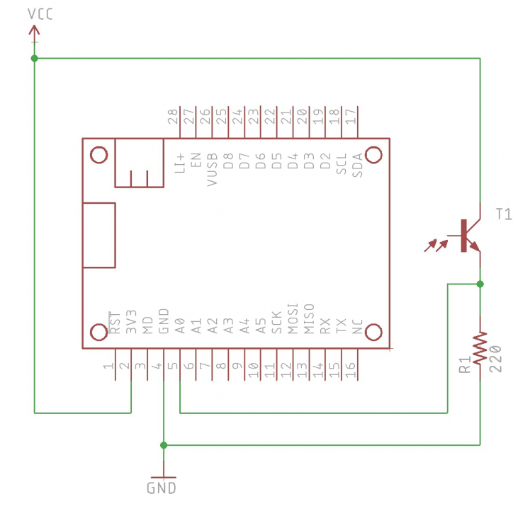
The digital pin A0 is used for the Output signal.
Connections :
Argon ----------------------------- LDR
VCC(3.3v) -> Vcc(3.3v)
GND -> Ground(0V)
A0 -> Data
The phototransistor is connected as follows:
- The short lead of the phototransistor connects to 3V3
- The long lead of the phototransistor connects to a 220 ohm (red-red-brown-gold) resistor and connects to ground.
- From the short lead of the photo, the transistor is connected to pin A0.
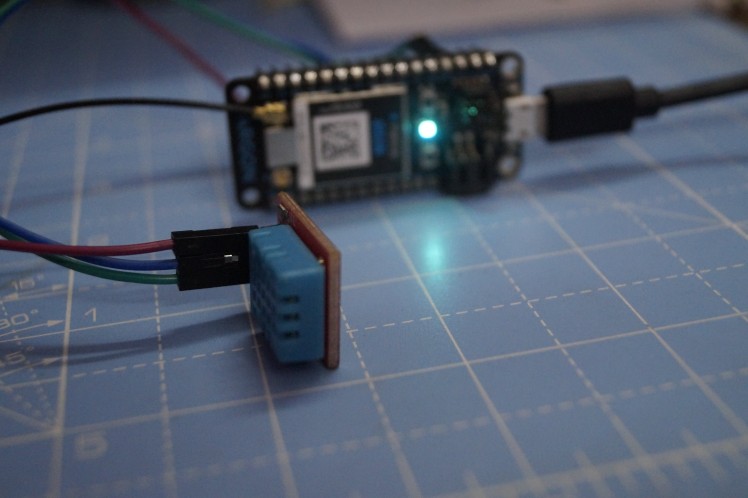
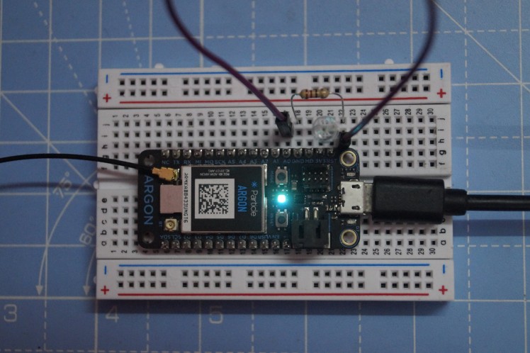
Overall connections
After connecting all the sensors, the connection looks like this.
Step 6: Program Modules
Make sure that all the connections are given as per the previous step.
DHT11:
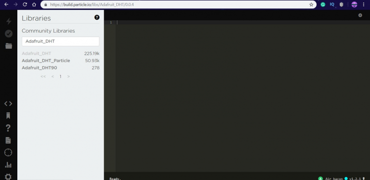
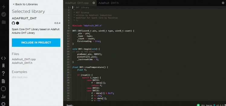
- Add Adafruit_DHT Library to the Particle Web IDE
- Click on DHT-test.ino or USE THIS EXAMPLE to fork the code.
- Change the configuration to DHT11
#define DHTTYPE DHT11		// DHT 11
//#define DHTTYPE DHT22		// DHT 22 (AM2302)
//#define DHTTYPE DHT21		// DHT 21 (AM2301)
- The Output response is shown below.
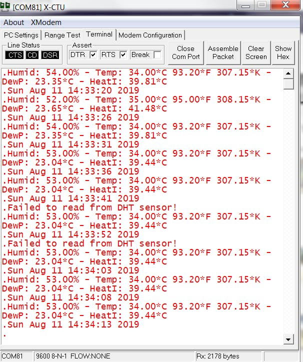
Since the data received from the DHT11 is too large, it takes several seconds to get the entire data. Whenever it couldn't receive the entire data within the period it prints the message "Failed to read from the DHT sensor is printed".
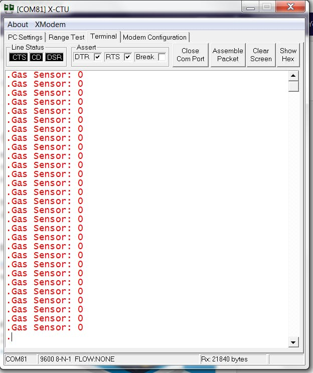
Air Sensor:
- Click on gas-sen.ino or USE THIS EXAMPLE to fork the code.
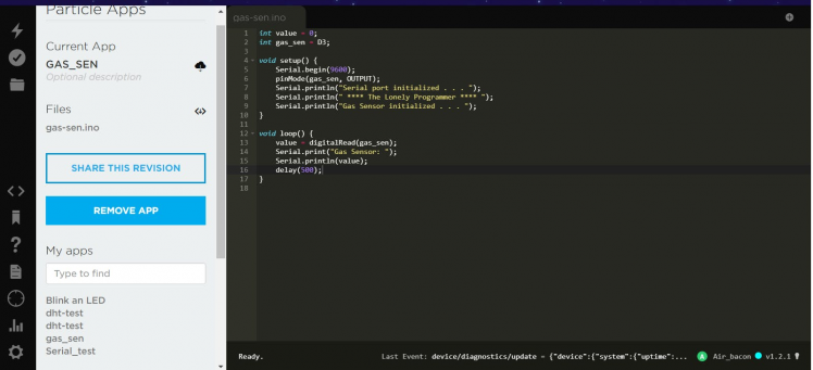
- The Output response is shown below.
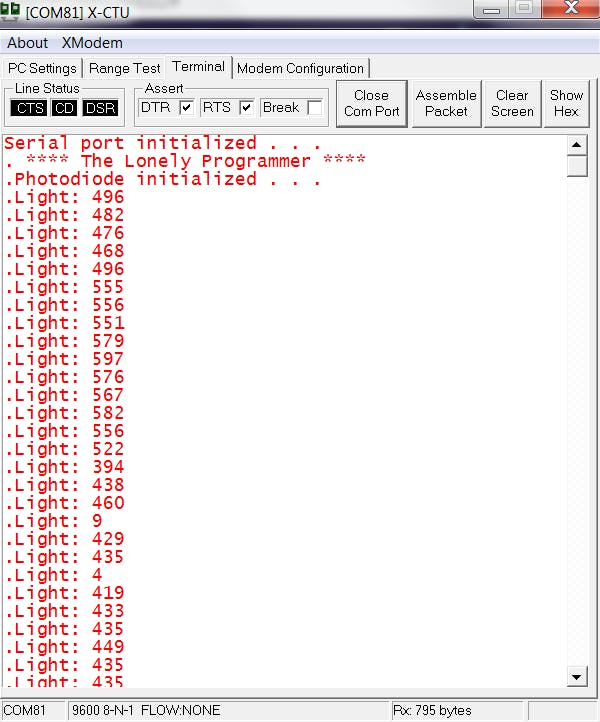
Photosensor:
- Click on photo.ino or USE THIS EXAMPLE to fork the code.

- The Output response is shown below.
Step 7: Integrating Firebase and Particle Cloud
Firebase has a ton of features including Realtime Database, Authentication, Cloud Messaging, Storage, Hosting, Test Lab and Analytics, but I’m only going to use Authentication and Real-time Database.
The data acquired by the Particle Argon is transmitted to the Firebase.
This is done by Publish & Subscribe operation via Firebase account.
Creating a Firebase Account
- First Login to the Google Firebase and create a new project and click "Add project" button to create a new project on Firebase.
- Give a name to your project and select your country, click the Create Project Button to start.
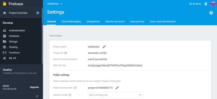
- Make sure that you note the Project ID which will be needed later when you program the hardware to connect to the project.
- Now click on Continue to get access the database created.
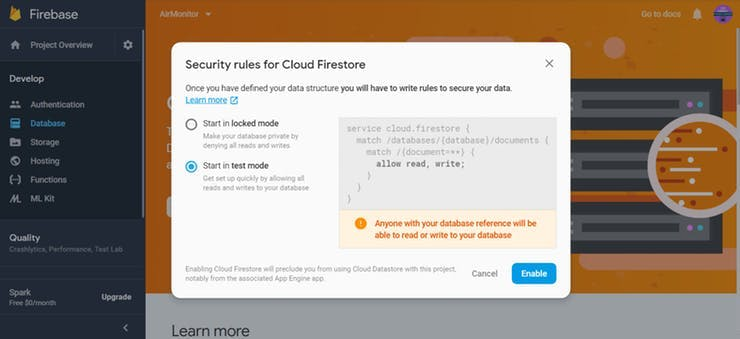
Now Click on Develop -> Database from the side menu, click the Create Database Button and Start the project in Test Mode as shown below.
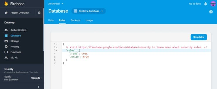
Enabling the Firebase will direct you to the Data and Rules tab, and verify whether the read and write functions are enabled.
Finally Open Project Settings and copy the Web API Key and the other parameters which will be used in the code.
The Firebase is configured to receive the data from the Particle Argon.
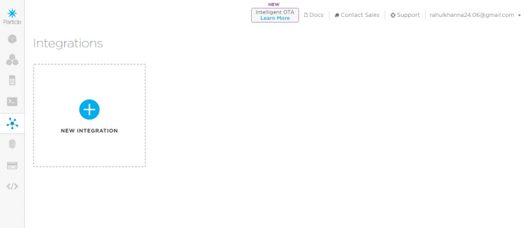
Configuring Particle Cloud
Now, Open the Particle Console, and select new integration. Select Webhook to configure.
Replace the URL from the Firebase account and other option as shown below.
Click the advanced settings and add the following code in the JSON DATA.
{
"temperature": "{{temp}}",
"humidity": "{{humid}}",
"gas": "{{gas}}",
"light": "{{light}}",
"published_at": "{{PARTICLE_PUBLISHED_AT}}"
}
Now click the Test button to verify whether the data is pushed to Firebase and you can see the success message popup.
Now you can see the data pushed from the Particle cloud to Firebase.
Step 8: Interfacing with Particle (Flowchart)
So this is how it works. First, we connect the Particle Argon board to Particle cloud. The Data from the sensors are published to the Particle Cloud via Particle.publish() function. With the data from the Particle cloud, the data is displayed in the GUI. In our case, let's assume that it is a dashboard.
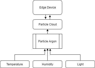
With the above system, we can display the temperate, humidity and light for every time interval.
For printing the sensor data over the serial, we upload the sensor_data.ino firmware to the Argon board.
the output looks similar to the following.
Publishing data to Particle Cloud
Initially, Data is published to the Particle cloud which will be directed to the Firebase account.
Refer to the Integration documentation from the Particle Console for Trigger and Integration response.
On uploading the Trigger integration code, we get the following response.
void loop() {
// Get some data
String data = String(10);
// Trigger the integration
Particle.publish("Firebase", data, PRIVATE);
// Wait 60 seconds
delay(60000);}
On minor tweaking, the sensor_data.ino publishes the data to a Particle cloud.
We combine all the data into a string format and pass it to the Particle cloud.
char data[256];
snprintf(data, sizeof(data), "{ "temp":%.2f, "humid":%.2f, "gas":%d, "light        ":"%d" }", t, h, value, analogvalue);

// Trigger the integration
Particle.publish("Firebase", data, PRIVATE);
This data is sent to the cloud every 60 seconds.
The Following outputs are recorded.
Now the data is published to the Firebase from the sensors.
Step 9: Dashboard
I've two ideas for displaying these data.
- Android App
- TFT Display
Android App
I developed an Android app which gets the data from the Firebase and displays it on the app.
I've added the application in the GitHub Repo.
TFT Display
Here, I'm planning to use the Adafruit PyPortal Display to create a dashboard.
Refer my previous post to get started with Adafruit PyPortal Display.
https://www.hackster.io/rahulkhanna/avengers-endgame-posters-on-adafruit-pyportal-135f1c
- Make sure that you download the Adafruit's Circuit-Python Request library
- Add the JSON file from the Particle Console, which contains the data being published from the Argon device.
JSON_GET_URL = "https://particle-a55e5.firebaseio.com/firebase/data.json"
Update the Firmware:
1. Download the correct erase file:
2. Double-click the reset button on the board to bring up the boardnameBOOT drive.
3. Drag the erase.uf2 file to the board name BOOT drive.
4. The onboard NeoPixel will turn yellow or blue, indicating the erase has started.
5. After approximately 15 seconds, the mainboard NeoPixel will light up green. On the NeoTrellis M4, this is the first NeoPixel on the grid
6. Double-click the reset button on the board to bring up the boardnameBOOT drive.
7. Drag the appropriate latest release of CircuitPython (https://adafru.it/Amd).uf2 file to the boardnameBOOT drive. It should reboot automatically and you should see CIRCUITPY in your file explorer again.
If the LED flashes red during step 5, it means the erase has failed. Repeat the steps starting with 2.
- Essential Python scripts are code.py and script.py
What we want to avoid is people accidentally sharing their passwords or secret tokens and API keys. So, we designed all our examples to use a secrets.py file, that is in your CIRCUITPY drive, to hold secret/private/custom data. That way you can share your main project without worrying about accidentally sharing private stuff.
Your secrets.py file should look like this: Inside is a Python dictionary named secrets with a line for each entry. Each entry has an entry name (say 'SSID' ) and then a colon to separate it from the entry key 'home SSID' and finally a comma, At a minimum, you'll need the SSID and password for your local WiFi setup.
- Drag and drop the code.py and script.py scripts to the device to upload the firmware.
The Sensor data is printed on the AdafruitPyportal.
Step 10: Let's See It Working
- You can find the data is being published on the Google Firebase. <attached>
-
This data which is logged can be display on either a website or with a mobile application.

- The Sensor data is displayed on the Adafruit PyPortal Display.
Now Let's see the code in action !!!
Working VideoGive a thumbs up if it helped you and do follow my channel for interesting projects. :)
Share this video if you like.
Happy to have you subscribed: https://www.youtube.com/channel/UCks-9JSnVb22dlqtMgPjrlg/videos
Thanks for reading!
Schematics, diagrams and documents
Code
Credits
the lonely programmer
Passionate Techie ! Robotics | Electronics | Programming Hey Geek! If you are in search of electronics projects, Arduino based projects or any Micro-controller based projects, this channel is for you. In this channel, we build electronics projects using the impressive and low-cost boards that are available today. If you are a maker or if you want to learn how to make your own Arduino projects and other interesting Robots, do subscribe the channel to be a part of this community. We develop our own hardware and software projects and will try to build something new. Don’t worry if you don’t know how to program. I'll share the algorithm if you face any difficulties.
Related products


Leave your feedback...