
How To Use Core2 Touch Screen Esp32 - M5stack & Visuino

Made by Ron / Displays / Home Automation / IoT
About the project
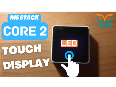
In this tutorial we will learn how to use the Core2 Touch Screen by making a button to control the internal LED. Watch the video!
Project info
Difficulty: Easy
Platforms: Arduino, Visuino, M5Stack
Estimated time: 1 hour
License: GNU General Public License, version 3 or later (GPL3+)
Items used in this project

Story
1 / 2
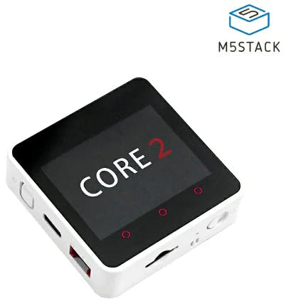
- M5Stack Core2 ESP32 more info here
- Visuino program: Download Visuino
1 / 2
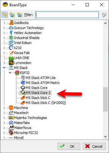
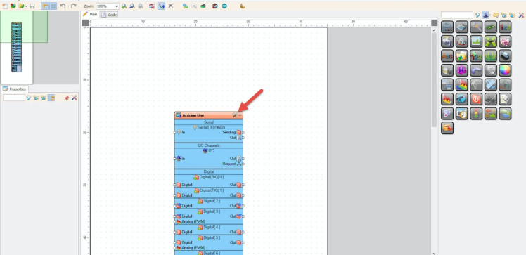
Start Visuino as shown in the first picture Click on the "Tools" button on the Arduino component (Picture 1) in Visuino When the dialog appears, select "M5 Stack Core 2" as shown on Picture 2
Step 3: In Visuino Add Components1 / 7
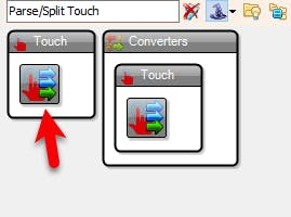
- Add "Parse/Split Touch" component
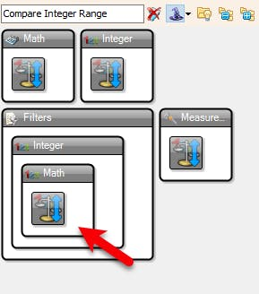
- Add 2X "Compare Integer Range" component
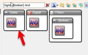
- Add "Digital (Boolean) And" component
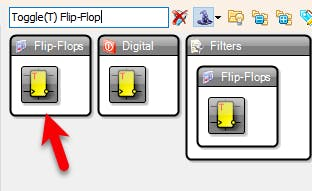
- Add "Toggle(T) Flip-Flop" component
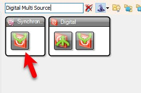
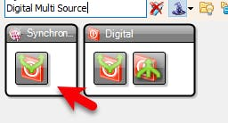
- Add "Digital Multi Source" component
- Add "Digital To Color" component
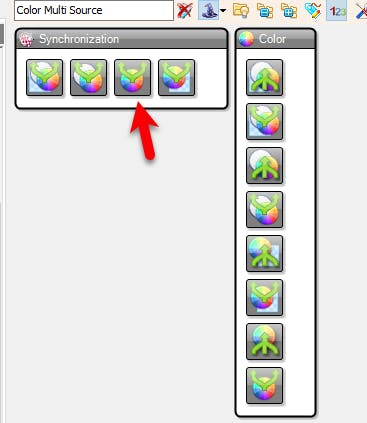
- Add "Color Multi Source" component
1 / 8
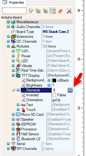
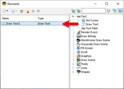
- Select M5 Stack Core 2 and in the editor Modules>TFT Display>Elements, click on [...] button, so that "Elements" window will open.
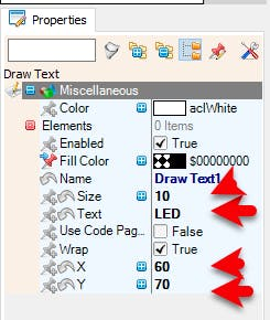
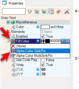
- In the Elements window drag "Draw Text1" and in the Properties window set "X to 60, "Y" to 70 and "Size" to 10, "Text" to LED, select "Fill Color" and click on the pin icon and select "Alpha Color SinkPin"
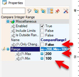
- Select "CompareRange1" and in the Properties window set "Only Changed" to False, "Range">"Max" to 200 and "Range">"Min" to 100
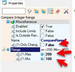
- Select "CompareRange2" and in the Properties window set "Only Changed" to False, "Range">"Max" to 200 and "Range">"Min" to 100
Note: with CompareRange1 and CompareRange2 you set the Rectangle detection on the screen, you can adjust the Max and Min values according to your needs.
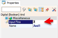
- Select "And1" and in the properties window set "Output pins" to 3
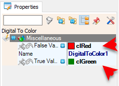
- Select "DigitalToColor1" and in the properties window set "False Value" to clRed and "True Value" to clGreen
1 / 2
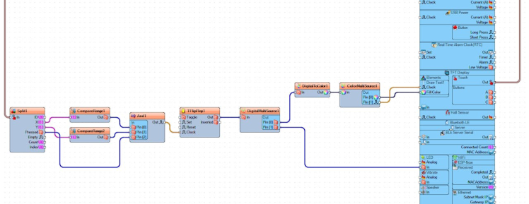
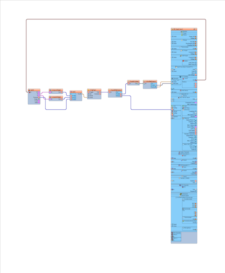
- Connect M5 Stack Core 2 > "TFT Display" > "Touch" pin [Out] to "Split1" pin [In]
- Connect "Split1" pin [X] to "CompareRange1" pin [In]
- Connect "Split1" pin [Y] to "CompareRange2" pin [In]
- Connect "CompareRange1" pin [Out] to "And1" pin [0]
- Connect "CompareRange2" pin [Out] to "And1" pin [1]
- Connect "Split1" pin [Pressed] to "And1" pin [2]
- Connect "And1" pin [Out] to "TFlipFlop1" pin [Clock]
- Connect "TFlipFlop1" pin [Out] to "DigitalMultiSource1" pin[In]
- Connect "DigitalMultiSource1" pin[0] to "DigitalToColor1" pin [In]
- Connect "DigitalMultiSource1" pin[1] to M5 Stack Core 2 > "LED" pin[In]
- Connect "DigitalToColor1" pin[Out] to "ColorMultiSource1" pin [In]
- Connect "ColorMultiSource1" pin[0] to M5 Stack Core 2 > "Draw Text1" pin[Fill Color]
- Connect "ColorMultiSource1" pin[1] to M5 Stack Core 2 > "Draw Text1" pin[Clock]
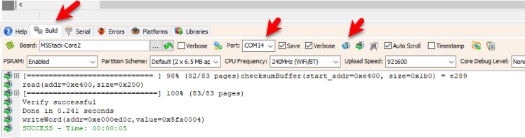
In Visuino, at the bottom click on the "Build" Tab, make sure the correct port is selected, then click on the "Compile/Build and Upload" button.
Step 7: PlayIf you power the M5 Stack Core, the display should start showing the "LED" text and if you touch it the internal board LED should turn ON or OFF.
Congratulations! You have completed your Internet Time project with Visuino. Also attached is the Visuino project, that I created for this Tutorial. You can download and open it in Visuino: https://www.visuino.eu
Schematics, diagrams and documents
Code
Credits
Related products


Leave your feedback...