
How To Make Simple Nodemcu Robotic Car

Made by rau7han / Games & Gaming / Robotics / IoT
About the project
Hey guys in this article we will see how to make this simple and amazing Robotic car., If you are a beginner in Robotics you must definitely
Project info
Items used in this project
Hardware components

Story
Hey, guys in this article we will see how to make this simple and amazing Robotic car., If you are a beginner in Robotics you must definitely give it a try to build this amazing robot.
I have given all the Arduino codes and circuit diagrams and a very detailed explanation about building this project.
Now let us go through some of the basic information about this project that we are building.
Thank You NextPCB:
This project was successfully completed because of the help and support from NextPCB. Guys if you have a PCB project, please visit their website and get exciting discounts and coupons.
NextPCB offers high-quality, reliable PCB starting at $1.9, and multilayer starting at $6.9. Also, everyone can enjoy free PCB assembly for 5 boards!
Also, Try HQDFM free online PCB Gerber viewer to check your PCB design and avoid costly errors.
What is a Robotic car?
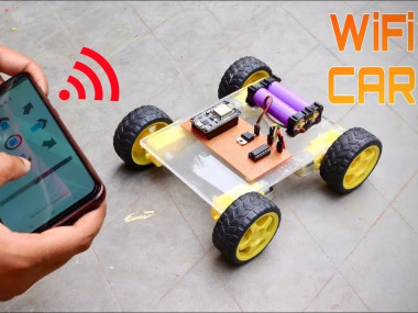
It is nothing but a car that can move in multiple directions the special thing about this robot that we are building is it can be controlled via smartphone.
And mainly, Except from the ordinary left, right, front, and back we can control this robot to move in sideways also and another special thing is this robot uses the in-expensive Nodemcu board which is known for its cost to-function factor.
If you have any questions in the build part you can watch the video given at the end of this article.
Now let us see the materials required to build this robot car.
Supplies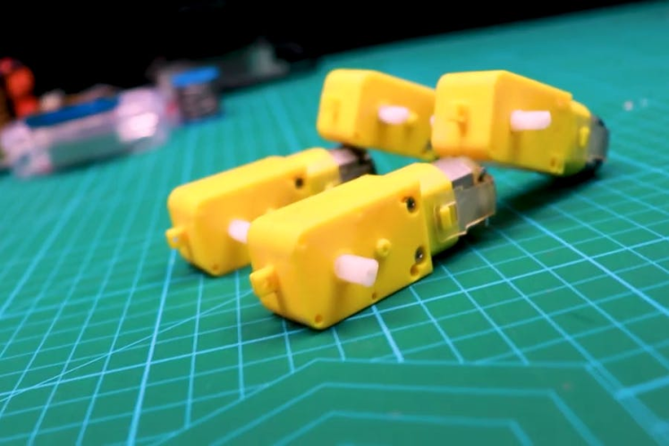
- BO Motor x4
- Nodemcu
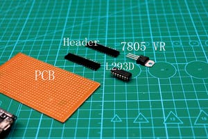
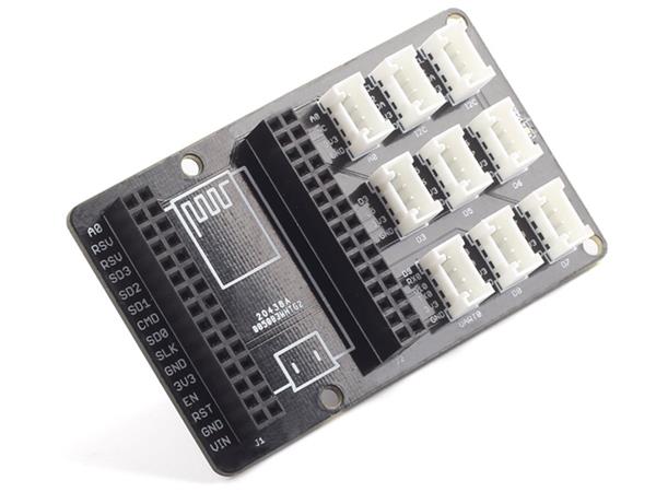
- Empty PCB and headers
- 7805 VR
- L293D Motor driver
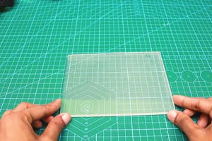
- Plexi board for the base
- Wheels
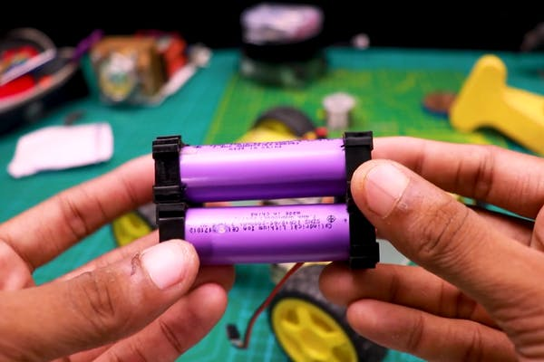
- Lithium-ion battery with holder
- Hot glue
- Arduino software
- Soldering lead and iron

The base of the car needs to be strong so I preferred to use the plexiglass, as we know they are very strong and lightweight and that is suitable for our project.
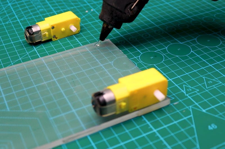
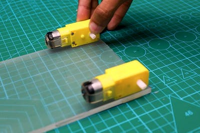
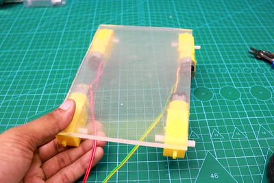
We will start by gluing the Bo motor or as few call it a gear motor to the plexiglass.
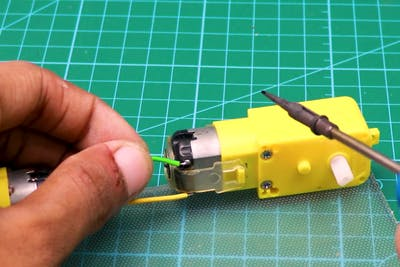
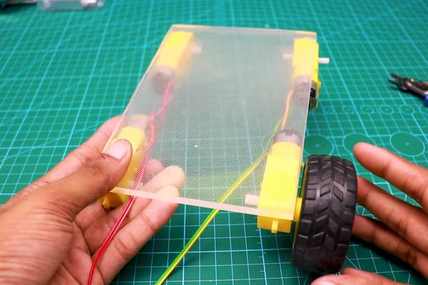
Repeat the same for the other 3 sides as well, After this is done we can establish the connection between motors this by soldering the wires to motor terminals.
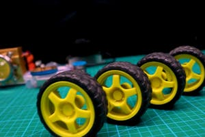
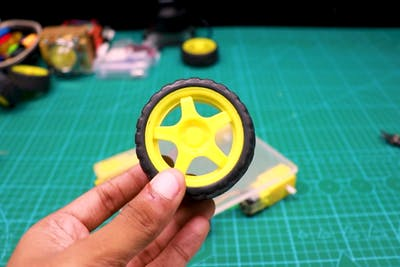
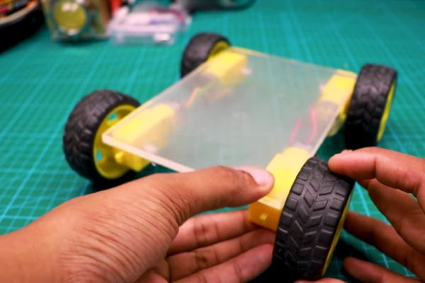
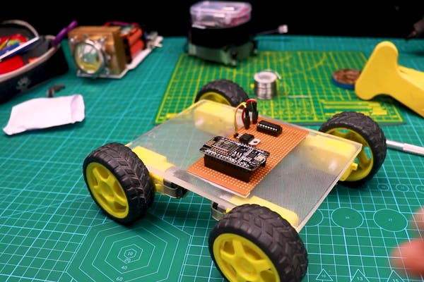
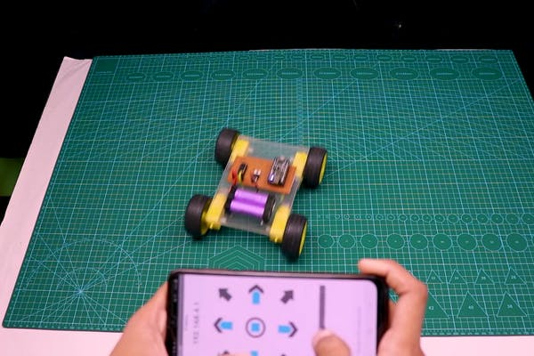
In the end, we can add the wheels, there is no need for any screw to secure the wheels to the motor shaft as we are using the press fit kind of fitting mechanism.
Add all 4 wheels to the motor and the car base is ready, Now we can add the electronics to this car.
Step 2: Circuit Diagram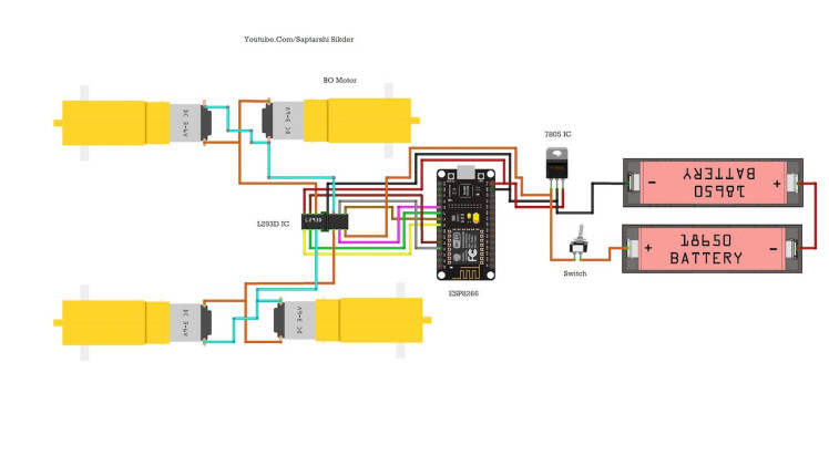
The circuit diagram that we are using to build this robot is very easy, and you can see itfrom the circuit diagram also.
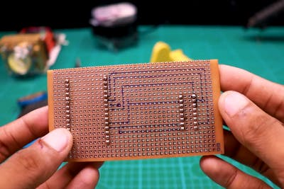
I will be using the empty PCB to make this but you can use breadboard also, the PCB saves lots of space and usage of wires so I chose to use PCB.
I will explain the circuit diagram for a better understanding.
The sides of the motors are connected as One and these will be connected to the motor driver pins, Pins 11 and 14 will be used to control one side of the motor, and pins 2 and 6 for the other sides.
Pins 1, 2, 7 and 8 of the driver will be connected to D5, D7, and D8, as pin 10 to D3 and pin 15, 16 to D4 and Vin.
Pins 12 will be connected to GND via the 7805, imagine with the use of wires the entire circuit would be messy, now we make the connections
Building the Circuit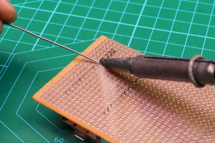

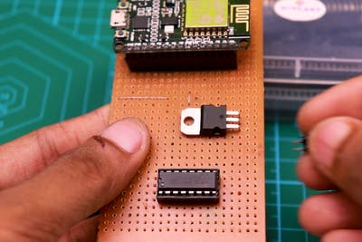
I will start by soldering the connector pins on the PCB, after that I follow sold, erasing the lines that I marked earlier for better understanding.
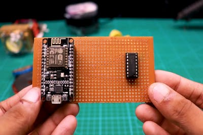
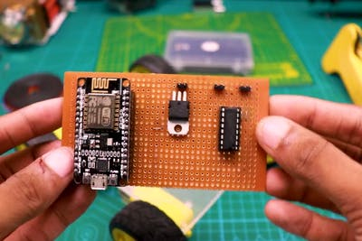
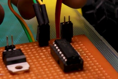
In the first place I soldered Nodemcu and l293motor driver on a PCB later I added the 7805 VR and other pin connectors.
In the end, you can see how the circuit looks, you can see no wires and this was the main aim of ours in using the PCB.
Adding the Power Source
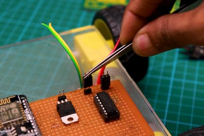
After the circuit is ready we can connect the motor wires to the pins, You can instead directly solder the pins but it will spoil the cleanliness of the circuit.
I chose to connect the wires via the pins, After everything is complete we can add the batteries, but before we need to upload the codes to Nodemcu.
Without the code, the project is just an empty car!
We will see how we can upload the code and what are the instructions you need to follow
Arduino Code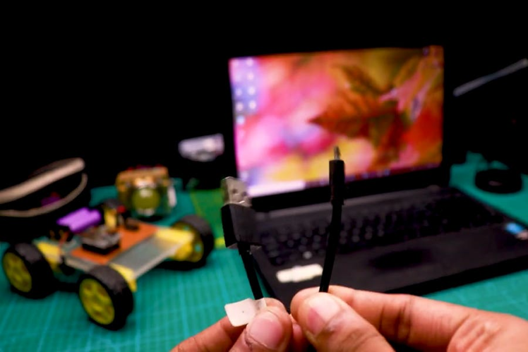
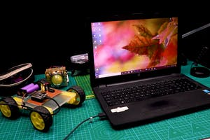
Connect the nodemcu board via the USB cable and open theIDE.
In the IDE paste the code, In the code, you can change the name of the network as you wish, You can keep the same if you want.
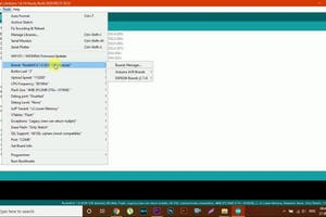
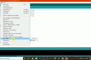
Once you have the code, check for the proper port number and type of board.
Note that your com port is different than mine, make sure to select the proper one.
Click on the upload button and now the project is ready and we can test the robot car for its working.
Working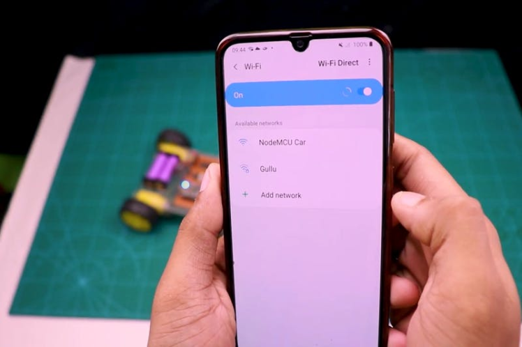
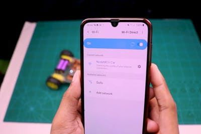

Using this car is very easy, all you have to do is switch on the power in the car.
Now turn on the Wi-Fi on your mobile and connect to the car network, once you connect the car open the application for controlling the car.
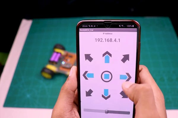
You can get the application here
Now from the panel on the application, you can control the car, Know that front, Back, Right, and left is not only the limit on our robot car :)
Working Video
Leave your feedback...