
How To Make Minimalistic Smart Curtains

Made by donutsorelse / Home Automation
About the project
By using a simple setup, we can accomplish everything we'd want in a Smart Curtain while keeping things cheap and easy. Wins all around.
Items used in this project
Hardware components

Story
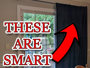
Smart devices are easier to make than ever as more resources become available for them and opening/closing the curtains every day feels like the perfect task for a robot. The goals are to not only activate the curtains on command, but also to determine the time of sunrise and sunset such that the curtains can just run autonomously from now on. Of course, if we're adding nice-to-have's anyway, we may as well throw in some additional features like Theater-Mode. The existing solutions are pretty pricey (looks like $250-300 from a quick browse, and also need at least an additional covering to hide the tracks), so you'll be happy to know this will cost a tiny fraction of that. What we're building it from is part of the fun as well.
Over time, the age old question of "where the heck did all this random junk come from??" becomes a more and more prevalent one as we accumulate stuff. Fortunately, it's pretty fun to repurpose it; like a puzzle of sorts. We'll be using items you likely have around the house to make a minimalistic Smart Curtain. As much as upcycling parts for a Smart Curtain may raise some eyebrows, no one wants to add an eyesore to their home for fun, myself included. What we're putting together today is hardly noticeable and works great, so let's get into it.
SuppliesIn addition to the upcycled parts, we do need some electronics. And hey, even these may be part of an old project in need of repurposing as well! I've provided affiliate links to the exact parts that I used (I promise to use all 8 cents I get for future projects like this ). Here are the electronics we're using:
- ESP8266 (microcontroller)
- L298N (for controlling the motor)
- 12V DC Motor
- Barrel plug adapter (for connecting the L298N to its power supply)
In terms of the items you may have lying around your garage that we're repurposing, here's what I used. A lot of it should be things that are pretty interchangeable with items most people will have, so this won't need to be overgeneralized. The fishing line can be any string that's strong enough and looks nice enough to be visible, the metal bracket could be anything similar or something like a shelf support, etc.
- Strong fishing line (it has to be extra strong line - normal fishing line will break)
- Wood pieces
- Screws
- Pulley
- Wheel (something for the string to rotate on)
- Binder clip
Especially considering that this is using old bits and pieces of things, it feels worthwhile to delve into the plan itself so you can make adjustments in advance before we get into all the specifics of how exactly to do each part of the project.
I am aiming for a more minimalistic approach to this. Instead of the more standard notion that you'll see with the ready-made solutions of having tracks, I'm going to just use a single string around a pulley that is controlled by a single motor. This requires that the string is completely taut or it won't work, but it has a few nice advantages. The only things in view are the pulley and the string, which will be strong fishing line in my case so it's not particularly noticeable. If it can't move the curtains any further in the direction it's meant to go, it will just rotate without moving it. The nice thing here is that this is a very simple workaround for power outages. If your blinds are open when the power goes out and the code defaults to assuming the blinds are closed, it could require additional logic with other setups. There's always a way to solve issues like these, but this way we don't even need to.
To keep the fishing line tight, I ended up with a small wooden enclosure. I was overthinking it a bit with a bracket or a shelf mount, but in the end the wooden enclosure was easier and still looked pretty nice because I could paint it to match the wall. At the end of the day, it just needs to be a way to mount the motor that will either be concealable, have decent aesthetics, or both.
On the opposite side of the curtain from the motor is the pulley. You could use a wheel or something, but this will probably be in view so it's worth it to have a nice looking part here.
The binder clip attaches the fishing line to the curtain. I realize binder clips aren't exactly items people use for home décor and aren't something you'd want front and center on a home improvement project, but this is easily concealed so no one should even see it.
As far as the electronics go, we're using the ESP8266 NodeMCU microcontroller because it's small, cheap, does everything we need, and has built in Wi-Fi that we can leverage for all the "smart" features. This does mean we need the L298N to control the motor, though, so it's worth a callout that you could make adjustments to the plan if having multiple components like that doesn't suit you or some such.
Step 2: Electronic Assembly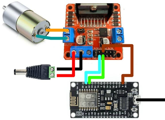
For anyone used to dabbling in Arduino projects, you may be all set with just the included pinout information, but I want to break this down a bit more for anyone newer to this type of tech. Another perk of the minimalistic setup is that it's simpler in terms of the electronics as well, so this may be a more doable smart home project for people to tackle in general. With that, let's get into the parts!
ESP8266 Microcontroller: This tiny and powerful device is the brain of our setup. It's programmed to control the motor based on inputs from various sources, like an HTTP server and sunrise/sunset data from an API. It also interfaces with the L298N motor driver to control the blinds' motor. This microcontroller's Wi-Fi capabilities make it perfect for IoT projects. We'll get to the code part in the next step that tells the ESP8266 how exactly to control the curtains.
L298N Motor Driver: This is a bridge between the microcontroller and the motor. Since the ESP8266 can't directly drive the motor due to power limitations, the L298N steps in to provide the necessary power handling capabilities. You'll connect the microcontroller's digital pins to the L298N's input pins. You'll also connect the motor to the output of the L298N. In our code, when the ESP8266 wants to open or close the blinds, it signals the L298N, which in turn drives the motor in the appropriate direction.
12V DC Motor: This is the muscle of our setup, and it physically moves the blinds. The motor's movement is controlled by the L298N motor driver, which receives instructions from the ESP8266. You need to securely attach the motor to the blinds and ensure the string is threaded correctly so the motor can pull the blinds open and closed.
The ESP8266 can be powered via a USB connection, but for the L298N and the motor, you'll need a 12V power source. For this, I ended up using a universal power adapter I had on hand with a barrel plug adapter. I double checked, and standard jumper wires are safe to use for the 12v connection, but it's something worth double checking with your own wires. Just be sure it's an appropriate gauge for the current your motor will draw.
I created the schematic without Fritzing for this one because I wanted to use images of the exact parts that were utilized to better convey exactly how to wire everything, visually. That said, let's also do a quick rundown of the connections.
Connecting the ESP8266 to the L298NConnect the ESP8266 to the L298N motor driver. The ESP8266 has GPIO pins (General Purpose Input Output) that can be used to control the L298N.
- Connect the D1 GPIO pin on the ESP8266 to the IN1 pin on the L298N.
- Connect the D2 GPIO pin on the ESP8266 to the IN2 pin on the L298N.
- Connect a GND pin on the ESP8266 to a GND pin on the L298N. This creates a common ground for the two devices.
Connect the OUT1 and OUT2 pins on the L298N to the motor. These will control the motor's direction, so if you need to reverse the direction the motor moves, you can easily do this by switching the connections.
Providing Power- Connect the 12V power supply to the VCC and GND inputs on the L298N. This will provide power to the motor.
- Connect the ESP8266 to a 3.3V power supply. This can be from a dedicated power supply, or via USB if you're programming the ESP8266.
Add TipAsk QuestionCommentDownload
Step 3: Code Time!
The code is provided and should work right out of the box. You just need to plug in a few fields and you'll be good to go. Plug in your wifi info, your API keys, and your latitude and longitude. We'll get to the Adafruit IO aspect of the api information momentarily. For the open weather map api, you can simply create a new account and go to the api key page by selecting it in the dropdown under your profile.
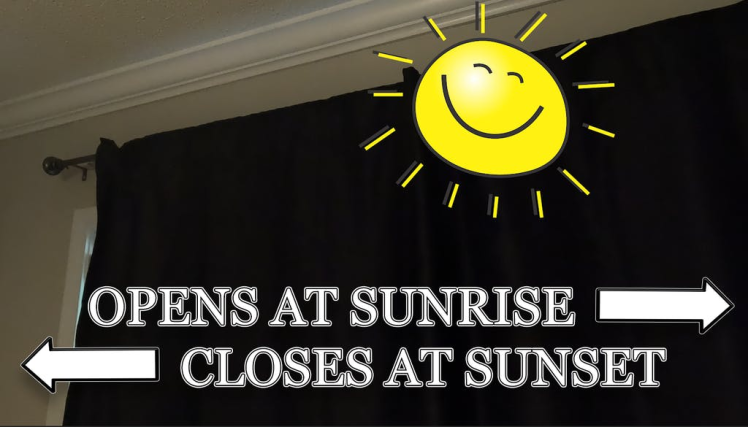
The reason we're using this api and the latitude and longitude is because we want to open the curtains before sunrise and after sunset. The time of sunrise and sunset changes as the year goes on, and to keep this as accurate as possible we fetch the time of sunrise and sunset every day. We open the curtains 10 minutes before sunrise and close it at sunset as is. This occurs in a simple check within the code, so it can be easily tweaked to your liking.
In general, we keep track of whether the curtains are open or closed. This keeps things really easy. If we say to activate the smart curtains, it'll just open or close them based on their current state. Then for any extra logic, like sunset for example, if the curtains are already closed at sunset we can just leave them as is.
We're always listening for commands that tell the Arduino to open or close the curtains. You'll find that there are two of these within the code. One opens or closes the curtains, and one only closes them which is handy for the Theater Mode feature in particular. With these commands though, you can easily send a number. Particularly if you decide to tweak the physical setup to use a more rigid system instead of the taut line, you can leverage this number in your code to adjust the amount of time the motor should move one direction or the other. This can be pretty critical in some setups, so being able to easily adjust it without unplugging the Arduino and adjusting the code is a major convenience. This can be accomplished by simply passing the value you receive from handleBlindsMessage to openCloseBlinds.
The code does use a few libraries, so let's get those setup as well. You can add them via Arduino IDE's Library Manager. To do so, simply go to Sketch -> Include Library -> Manage Libraries and then search for the library needed.
The libraries to add are:
- ArduinoJson
- AdafruitIO_WiFi
This code uses ESP8266 board, and if you haven't installed the ESP8266 board definitions in the Arduino IDE, you can do so by going to File -> Preferences and under Additional Board Manager URLs, add http://arduino.esp8266.com/stable/package_esp8266com_index.json. Then, go to Tools -> Board -> Board Manager, search for esp8266 and install it. After installation, you can select your specific ESP8266 board from Tools -> Board.
For just getting started and ensuring that your electronics are hooked up correctly, you can very easily utilize the code provided to test your setup by just calling openCloseBlinds in your loop to ensure that your motor is moving like it should.
The last note with the code is that some motors may move too fast. I have included a commented out function that slows down the speed of the motor. You can tweak the speed by setting the value of motorSpeed.
Step 4: IFTTT and Adafruit IO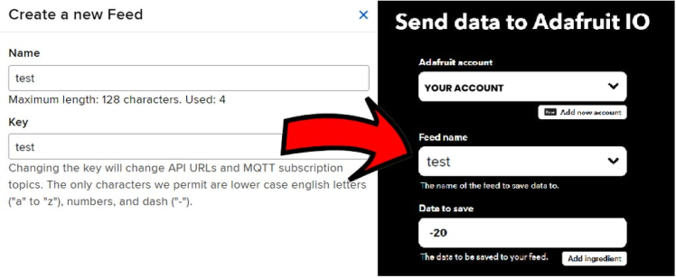
This may sound a bit intimidating, but it's actually pretty easy and is the nicest of the solutions I explored for this. The goal of this segment is to make it such that you'll be able to use voice commands and smart home functionality to control your smart blinds. This solution uses IFTTT and Adafruit IO, which can both be used for free.
We're going to start with the Adafruit IO part because it can take a little bit for the feed we'll be utilizing to show up in IFTTT, so making it first streamlines this process a bit. You can go to the Adafruit IO page within their site and make your account. What we need is a feed, which you can see in the sub-options. Simply create a new feed with the name you want and you'll be good to go for the next part.
IFTTT stands for If This Then That and is a simple logic controller that can be leveraged to help us setup the use of our smart curtain with our smart home setup. I'm using Google Assistant but you could use something like an Alexa just as easily. Navigate to the IFTTT site, setup your account if needed, and click Create. You'll see the simple "IF" and "THEN" options. Choose IF first. Select your home assistant. In my case it's Google Assistant V2. This is what you have if you use Google Home.
Once this is setup, select THEN within your applet. Search for and select Adafruit IO. You'll be able to connect your Adafruit IO account and, by this point, you should see your Adafruit IO feed as well. If it doesn't show up yet, just give it a few minutes and it will. When the feed is available to select, you
Add TipAsk QuestionCommentDownload
Step 5: Installation!Here already? Yes indeed, we're ready to setup our smart blinds. As noted in the planning segment, I'll be going through the parts I utilized but this can be easily tweaked to accommodate what you have on hand.
First, measure out the length of fishing line that you need such that it's just barely longer than the full loop. To reiterate, I am using extra strong fishing line - the standard fishing line will likely break! Loop the string through the pulley and then nab your binder clip. Put the ends of the fishing line over lapping on top of the binder clip and super glue them in place. This hides the less nice looking part where the line connects and gets it solidly attached to the clip.
While that's drying, it's time to create the housing for the motor. It needs to be kept securely in place to ensure the line stays tight. I ended up with a simple wooden structure that I painted to match the color of my walls. The wood can be easily screwed into the walls and doesn't give the motor any wiggle room to slacken the line. To further improve the aesthetics, I have this mounted way off to the side where it is concealed by our cabinets.
The last bit of the prep work may be a non-issue depending on what you purchased for your motor. We need something for the line to rest on. For this, I used a wheel from a tank robot I took apart. Typically, motors will have a D shape so that you can tighten a D shaft connector onto it such that the bolt faces the flat side and the attachment can rotate around without coming loose. I just glued the wheel onto one of these D shaped motor attachments and was good to go.
And now for the finale - actual installation! I wanted the pulley in a specific location, so I mounted it first. Next, the binder clip needs secured behind the curtains such that it will be concealed from view and can easily pull the curtains back and forth. Next, pull the motor housing such that the line is as tight as possible and secure it against the wall. Last, plug in the electronics and... that's it! You have Smart Curtains that can use voice commands, open for sunrise, close at sunset, and can easily handle additional capabilities. Take it for a whirl if you're so inclined, and then we'll jump right into those additional capabilities.
Add TipAsk QuestionCommentDownload
Step 6: Theater Mode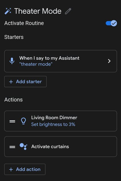
This is a little bonus, because why not. If we already have smart curtains, we may as well use that to our advantage to set the stage for an ideal movie watching experience.
You may have already noticed in the code that there's a second call we're listening for from Adafruit. This is used to strictly close the blinds. As that implies, you'll need to get this setup on IFTTT and Adafruit IO, but this all uses identical logic to what we did the first time with just a different feed name and command. There's a little trick to getting this all to cooperate, but once you know it it's easy and everything is included here.
Start off as you normally would and add a new Routine in your Google Home app. Add your activation command, but be sure that it's something different from what you say to activate the IFTTT applet. For example I setup my Google Home routine to activate on "Theater Mode", whereas the IFTTT applet trigger is "Activate Close Blinds". Include any actions that you feel like including, like dimming the lights. Then, add a custom command as an action. In this, write what you would say to activate your IFTTT applet. Doing this will correctly initiate the applet, inform the Adafruit IO feed, and make it to your ESP8266 all as it would with a normal voice command.
And with that, you're good to go and can easily add whatever bonus features you want for Theater Mode (or whatever you end up coming up with) as well! I'll be curious what other features people come up with. I know I'm a little more than tempted to try to figure out how to automatically get popcorn going...
Regardless, hopefully you enjoyed this solution to a very inexpensive Smart Curtain setup!
Schematics, diagrams and documents
Code
Credits
Related products


Leave your feedback...