
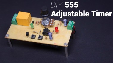
How To Make An Adjustable 555 Timer Relay Switch

Made by ElectroGuruji / Clocks / Home Automation / Productivity
About the project
Learn how to make a precisely adjustable timer with a variable delay from 1 - 100 seconds that uses the 555 IC. The 555 timer is configured as a Monostable Multivibrator. The output load is driven by the relay switch which is in turn controlled by the timer circuit.
Project info
Items used in this project

Story
Learn how to make a precisely adjustable timer with a variable delay from 1 - 100 seconds that uses the 555 IC. The 555 timer is configured as a Monostable Multivibrator. The output load is driven by the relay switch which is in turn controlled by the timer circuit.
Since the project only involves assembling a simple circuit by following the schematic, it will only take an hour to make.
Don't forget to Subscribe for more projects: YouTube
Step 1: Parts & Tools

Electronic Components:
- 1x 555 AliExpress
- 2x 3KΩ Resistor AliExpress
- 4x 10KΩ Resistor AliExpress
- 1x 1MΩ Potentiometer AliExpress
- 1x IN4004 Diode AliExpress
- 2x Tactile Momentary Push Buttons AliExpress
- 2x 5mm LED AliExpress
- 2x 100uF Capacitor AliExpress
- 2x 0.1uF (100nF) Capacitor AliExpress
- 1x 2 Pin Screw Terminal AliExpress
- 1x 3 Pin Screw Terminal AliExpress
- 1x 12VDC Relay AliExpress
- 1x 12VDC Adapter AliExpress
- 1x SPDT Slide Switch AliExpress
- 1x PCB AliExpress
Tools:
- Soldering Iron AliExpress
- Soldering Wire AliExpress
- Mini PCB Hand Drill + Bits AliExpress
- Wire Cutter AliExpress
- Wire Stripper AliExpress
- Soldering Helping Hands AliExpress
You can also Buy the PCB: PCBWay
Step 2: 555 Explained


The 555 is a highly stable device for generating accurate time delays or oscillation. Additional terminals are provided for triggering or resetting if desired. In the time delay mode of operation, the time is precisely controlled by one external resistor and capacitor. The circuit may be triggered and reset on falling waveforms, and the output circuit can source or sink up to 200mA or drive TTL circuits.
In the Monostable mode, the LM555 timer acts as a one-shot pulse generator. The pulses being when the LM555 timer receives a signal at the trigger input that falls below a 1/3 of the voltage supply. The width of the output pulse is determined by the time constant of an RC network. The output pulse ends when the voltage on the capacitor equals 2/3 of the supply voltage. The output pulse width can be extended or shortened depending on the application by adjusting the R and C values.
The external capacitor is initially discharged by a transistor inside the timer. Upon application of a negative trigger pulse of less than 1/3 VCC to pin 2, the internal flip-flop is set which both releases the short circuit across the capacitor and drives the output high. The voltage across the capacitor then increases exponentially for a period of t = 1.1RC , at the end of which the voltage equals 2/3 VCC. The internal comparator then resets the flip-flop which in turn discharges the capacitor and drives the output to its low state.
Step 3: Circuit Schematic

The LM555 has a maximum typical supply voltage rating of 16V while the relay's armature coil is enabled at 12V. Hence a 12V power supply is used to minimize the number of components such as linear voltage regulators. When pin 2 of the LM555 is triggered (by shorting it to ground) through the momentary switch S1, the timer is started.
The timer generates an output pulse with an ON time period determined by the RC network i.e t = 1.1RC . In this case, the fixed value of the capacitor is 100uF. The value of R consists of a 10KΩ resistor in series with a 1MΩ potentiometer. We can vary the potentiometer to change the time period of the output pulse.
For example, if the potentiometer is set to 0Ω, the value of R is equal to 10KΩ. Hence t = 1.1 x 10K x 100u = 1 second.
But if the pot is set to 1MΩ, the value of R is equal to 1MΩ + 10KΩ = 1010KΩ. Hence t = 1.1 x 1010K x 100u = 100 seconds.
When pin 4 of the LM555 is triggered (by shorting it to ground) through the momentary switch S2, the timer is reset.
When the timer starts, the relay turns ON. Hence the Common(COM) terminal of the relay is shorted to the Normally Open (NO) terminal. A high power load can be connected to this terminal such as a light bulb or water pump. A transistor Q1 acts as a switch an ensures sufficient drive current is provided to the relay. Diode D1 acts as a flyback diode which protects the transistor Q1 from voltage spikes caused by the relay coil.
LED2 turns on in order to indicate when the relay is turned ON. LED1 indicates the circuit is powered ON. An SPDT switch S3 is used to switch the circuit ON. Capacitors C2 and C4 are used to filter noise in the supply line.
Eagle Schematic: GitHub
Step 4: PCB Fabrication


Estimated Time: 30 mins
I fabricated the board using the Iron Method.
I drilled four mounting holes in each corner with a diameter of 3mm.
The PCB size is 10cm X 5cm .
Step 5: Circuit Assembly


Estimated Time: 30 mins
Place and solder all the components onto the PCB. Double check components with polarities. Lastly, solder the Power adapter to the PCB.
Once every component is soldered onto the PCB, you can connect the load across the relay terminals.
Step 6: Start and Reset the Timer


I connected a 24VDC indicator light across the Common & Normally Open terminals of the relay. When the timer is ON, these terminals are shorted thereby completing the circuit.
You can vary the Potentiometer to adjust and set the time delay.
Momentary switch S1 is used to Start the timer. The timer can be reset during the timing cycle by pressing the momentary switch S2.
Step 7: Support These Projects

- YouTube: Electro Guruji
- Instagram: @electroguruji
- Twitter: ElectroGuruji
- Facebook: Electro Guruji
Are you an engineer or hobbyist who has a great idea for a new feature in this project? Maybe you have a good idea for a bug fix? Feel free to grab the schematics from GitHub and tinker with it. If you have any questions/doubts related to this project, leave them in the comments section and I will try my best to answer them.
Schematics, diagrams and documents
Code
Credits
Related products


Leave your feedback...